

Unicorn Digital Timepiece User Manual

Digital Timepiece
User’s Guide
Mark of the Unicorn, Inc.
1280 Massachusetts Avenue
Cambridge, MA 02138
Business voice: (617) 576-2760
Business fax: (617) 576-3609
Tech support fax: (617) 354-3068
Tech support email: techsupport@motu.com
Web site: http://www.motu.com
SAFETY PRECAUTIONS AND ELECTRICAL REQUIREMENTS
WARNING: T O REDUCE THE RISK OF FIRE OR ELECTRICAL SHOCK, DO NOT EXPOSE THIS APPLIANCE T O RAIN OR O THER MOISTURE.
CAUTION: T O REDUCE THE RISK OF ELECTRICAL SHOCK, DO NO T REMO VE CO VER. NO USER-SER VICEABLE PARTS INSIDE. REFER SER VICING T O
QUALIFIED SER VICE PERSONNEL.
WARNING: DO NO T PERMIT FINGERS T O TOUCH THE TERMINALS OF PLUGS WHEN INST ALLING OR REMO VING THE PLUG T O OR FROM THE OUTLET.
WARNING: IF NO T PROPERLY GROUNDED THE Digital Timepiece COULD CA USE AN ELECTRICAL SHOCK.
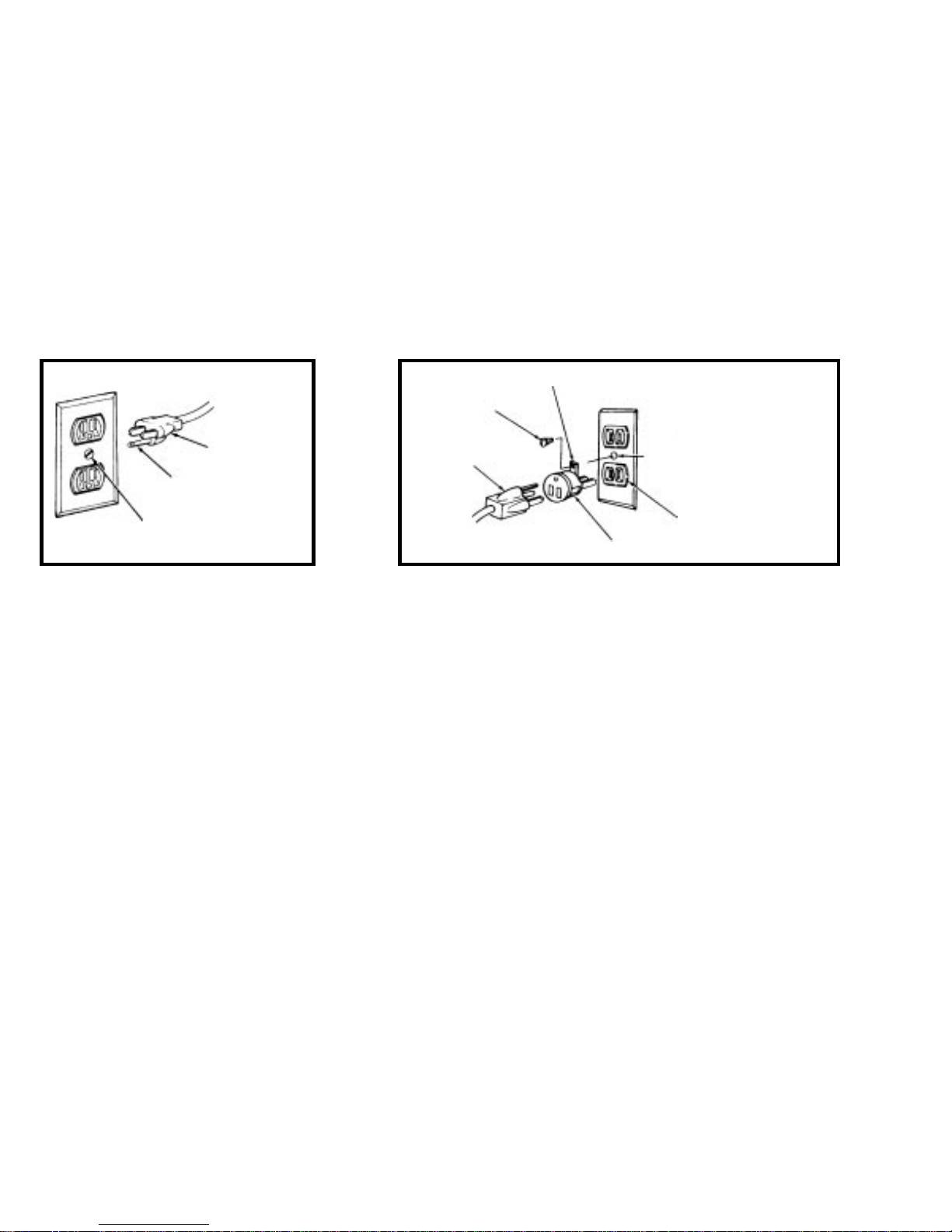
The Digital Timepiece is equipped with a three-conductor cord and grounding type plug which has a grounding prong, appro ved by Underwriters' Laboratories and the Canadian Standards Association.
This plug requires a mating three-conductor grounded type outlet as shown in Figure A below .
If the outlet you are planning to use for the Digital Timepiece is of the two prong type, DO NO T REMOVE OR AL TER THE GROUNDING PRONG IN ANY MANNER. Use an adapter as shown below
and always connect the grounding lug to a known ground. It is recommended that y ou have a qualified electrician replace the TWO prong outlet with a properly grounded THREE prong outlet. An
adapter as illustrated below in Figure B is availab le for connecting plugs to two-prong receptacles.
Figure A Figure B
Grounding lug
Screw
3-prong plug
3-prong plug
Make sure this is connected
to a known ground.
Grounding prong
Properly grounded 3-prong outlet
Two-prong receptacle
Adapter
WARNING: THE GREEN GROUNDING LUG EXTENDING FROM THE AD APTER MUST BE CONNECTED TO A PERMANENT GROUND SUCH AS TO A
PROPERLY GROUNDED OUTLET BOX. NOT ALL OUTLET BO XES ARE PR OPERLY GROUNDED.
If you are not sure that your outlet box is properly grounded, ha ve it check ed by a qualified electrician. NOTE: The adapter illustrated is for use only if y ou already have a properly grounded two-prong
receptacle. Adapter is not allo wed in Canada by the Canadian Electrical Code. Use only three wire e xtension cords which have three-prong grounding type plugs and three-prong receptacles which
will accept the Digital Timepiece plug.
IMPORT ANT SAFEGU ARDS
1. Read instructions - All the safety and operating instructions should be read before operating the Digital Timepiece.
2. Retain instructions - The safety instructions and owner's manual should be retained f or future reference.
3. Heed Warnings - All warnings on the Digital Timepiece and in the owner's manual should be adhered to.
4. Follow Instructions - All operating and use instructions should be followed.
5. Cleaning - Unplug the Digital Timepiece from the computer before cleaning and use a damp cloth. Do not use liquid or aerosol cleaners.
6. Overloading - Do not overload wall outlets and extension cords as this can result in a risk of fire or electrical shock.
7. Power Sources - This Digital Timepiece should be operated only from the type of power source indicated on the marking label. If you are not sure of the type of power supply to y our location, consult your local power company.
8. Power-Cord Protection - P ower-supply cords should be routed so that the y are not likely to be walked on or pinched b y items placed upon or against them. P ay particular attention to cords and plugs, conv enience receptacles, and
the point where they exit from the Digital Timepiece.
9. Lightning - For added protection for the Digital Timepiece during a lightning storm, unplug it from the wall outlet. This will prev ent damage to the Digital Timepiece due to lightning and po wer line surges.
10. Servicing - Do not attempt to service this Digital Timepiece yourself as opening or removing covers will e xpose you to dangerous voltage and other hazards. Ref er all servicing to qualified service personnel.
11. Damage Requiring Service - Unplug the Digital Timepiece from the computer and refer servicing to qualified service personnel under the following conditions.
a. When the power supply cord or plug is damaged.
b. If liquid has been spilled or objects have fallen into the Digital Timepiece.
c. If the Digital Timepiece has been exposed to rain or water .
d. If the Digital Timepiece does not operate normally by follo wing the operating instructions in the owner's manual.
e. If the Digital Timepiece has been dropped or the cabinet has been damaged.
f. When the Digital Timepiece exhibits a distinct change in perf ormance, this indicates a need for service.
12. Replacement Parts - When replacement parts are required, be sure the service technician has used replacement parts specified by the manufacturer or have the same characteristics as the original part. Unauthorized substitutions
may result in fire, electric shock or other hazards.
13. Safety Check - Upon completion of any service or repairs to this Digital Timepiece , ask the service technician to perform safety checks to determine that the product is in safe operating conditions.
ENVIRONMENT
Operating Temperature: 10°C to 40°C (50°F to 104°)
A V OID THE HAZARDS OF ELECTRICAL SHOCK AND FIRE
Do not handle the power cord with wet hands. Do not pull on the power cord when disconnecting it from an A C wall outlet. Grasp it by the plug.
INPUT
Line V oltage: 100 - 120 volts A C, RMS (US and Japan) or 220 - 250 v olts AC, RMS (Europe). F requency: 47 - 63 Hz single phase . P ower: 7 watts maximum.
CAUTION: D ANGER OF EXPLOSION IF BATTERY IS REPLACED . REPLA CE ONLY WITH THE SAME OR EQUIVALENT TYPE RECOMMENDED BYMANUFA CTURER. DISPOSE OF USED B A TTER Y A CCORDING TO MANUF A CTURER’S INSTRUCTIONS.

CHAPTER
Chapter 1 –
5
5
5
5
Chapter 2 –
9
9
9
10
10
11
12
Chapter 3 –
13
14 Computers
16 Digital Multitrack tape decks
18 Working with the Tascam DA-88
22 Word Clock Devices
24 S/PDIF devices
27 Video
28 SMPTE time code devices
29 MIDI Time Code devices
29 Alesis LRC
30 MMC control surfaces
Chapter 4 –
33
34
34
36
36
36
36
36
36
37
37
Contents
About the Digital Timepiece
Packing list
About this guide
Register for technical support
What is the Digital Timepiece?
Degrees of Accuracy
Before you go any further…
Sample-accurate sync
Frame-accurate sync with phase-lock
Frame-accurate sync
Frame-accurate triggering
Front Panel Quick Reference
Rear Panel Quick Reference
Installation
Overview
Front Panel Settings
Overview
About synchronization
Choosing a time base mode
Internal
MTC
LTC
Video/Internal
Video/MTC
Video/SMPTE (LTC)
Video/VITC
Video/Sony
37
Word 1x/Internal
37
Word 1x/MTC
37
Word 1x/LTC
37
Word 256x/Internal
37
Word 256x/MTC
38
Word 256x/LTC
38
Word 1x/Video/Internal
38
Word 1x/Video/MTC
38
Word 1x/Video/LTC
38
Word 1x/Video/VITC
38
Word 1x/Video/Sony
39
S/P DIF/Internal
39
Control track 1 or 2
39
Word 1x/Control track 1 or 2
39
DA-88
39
Word 1x/DA-88
39
ADAT
39
Word 1x/ADAT
40
the SMPTE frame rate setting
41
The Word clock rate setting
Chapter 5 –
Chapter 6 –
Chapter 7 –
Example Setups
45
Overview
45
The Digital Timepiece as master
46
Video as time base master
47
Devices that cannot act as a slave
48
Using an Alesis BRC or Tascam RC-848
Converting/Generating Time Code
49
Overview
49
Starting playback
49
Deferred playback
50
Generating or Converting time code
Striping Time Code
53
Overview
54
General procedure
55
Striping frame-locked LTC onto video
55
Striping SMPTE on a multitrack tape deck
55
Regenerating fresh time code
56
Lengthening a SMPTE track
57
Regeneration and time code bits
57
Recording VITC
3

58
Recording burn-in & other graphics
Chapter 8 –
Chapter 9 –
MIDI Machine Control
59
Overview
59
How MMC works
59
A recommended scenario for MMC
60
MMC Device IDs
62
Setting up MMC slaves
63
Setting up a MMC transport master
64
MMC control of record functions
Digital Timepiece & Performer
67
Overview
67
Getting the Digital Timepiece to appear in Performer’s MMC window
67
Slaving Performer
68
Using Performer as transport master
69
MMC record commands
71
Video streamers
72
Controlling a DA-88/SY-88 with Performer
Chapter 10 –
Digital Timepiece & Other
Sequencers
75
Overview
75
Establishing communication
75
Slaving your sequencer
76
Using your sequencer as transport master
77
MMC record commands
Chapter 11 –
79
79
81
81
81
82
Chapter 12 –
83
84
85
85
86
88
91
91
92
Chapter 13 –
93
93
94
Chapter 14 –
95
98
98
98
Digital Timepiece & OMS
Overview
ClockWorks and OMS
Preparing ClockWorks
Preparing OMS
Adding the DTP to your OMS setup
Using AV Controls
Digital Timepiece & Pro Tools
Overview
Pro Tools, ClockWorks, OMS & FreeMIDI
Enabling OMS emulation in FreeMIDI
Preparing OMS
Pro Tools as master
Pro Tools as slave
Pro Tools and Triple-sync
Transport control
Lockup time
Alesis LRC
Using an Alesis LRC
LRC button functions
LRC Calibration
Troubleshooting
Common problems and solutions
Customer Support
Replacing Disks
Technical Support
4

CHAPTER
1
About the Digital Timepiece
Thank you for purchasing the Digital Timepiece™!
PACKING LIST
Your Digital Timepiece box should have the
following items in it. If not, contact Mark of the
Unicorn customer service at (617) 576-2760.
■
Digital Timepiece
■
Power cord
■
Digital Timepiece Manual
■
ClockWorks™ Manual
■
ClockWorks™ software installer disks
■
Registration card
ABOUT THIS GUIDE
This guide provides important information about
installing and setting up the Digital Timepiece.
There is a companion guide for the Macintosh
software console that ships with the Digital
Timepiece called the
ClockWorks User’s Guide
.
WHAT IS THE DIGITAL TIMEPIECE?
Think of the Digital Timepiece as the synchronization hub for your recording studio. It provides
stable, centralized synchronization services for
most analog, digital audio, and video equipment
found in today’s recording studio. Until now,
locking together ADAT™, DA-88™, Pro Tools™,
word clock audio devices, S/PDIF devices, video
decks, SMPTE time code devices, MIDI Machine
Control devices and computers has been difficult
— if not impossible. The Digital Timepiece can
connect to all of these types of devices and
synchronize them with one another.
A computer is not required
You do not need a computer to use a Digital
Timepiece. Essential settings are available directly
on the front pan el. Once y ou ch oose an operatio nal
mode with the TIME BASE controls, the Digital
Timepiece will generate or convert all forms of
synchronization necessary to keep all connected
devices synchronized with one another.
REGISTER FOR TECHNICAL SUPPORT
Before you go any further, take a moment to fill out
and mail in the registration card included in this
package. Doing so entitles you to:
■
free, unlimited technical support via email
■
free newsletters
■
new product information
Since Mark of the Unicorn can only provide
customer service and technical support to
registered users, please send in the card right away.
Degrees of accuracy
Digital audio devices found in today’s studio
support varying degrees of accuracy when it comes
to synchroniza tion. The Digital T imepiece s upp lies
the best possible accuracy for each type of device
that it sup ports. Mo st devices fall into the f ollowing
basic categories of accuracy:
■
Sample accurate sync
■
Frame-accurate sync with phase lock
■
Frame-accurate sync with no phase lock
■
Frame-accurate triggering
5

Synchronization firsts
The Digital Timepiece offers several synchronization firsts. For example, you can now
synchronize a stack of Alesis ADAT™ recorders
with a stack of Tascam DA-88™ recorders with
‘plug-and-play’ ease and sample-accurate timing.
The Digital Timepiece also works with other
devices that support the ADAT and DA-88
proprietary sync protocols, such as the Panasonic
MDA-1™, SONY PCM-800™ and Tascam
DA-38™.
The components of sync
The Digital Timep iec e su p p lies all o f the necessary
components for stable, sample-accurate synchronization: address (SMPTE time code location and
audio sample number), time base (word clock),
and machine control (for transport and cueing).
You choose an external source — or the Digital
Timepiece itself — as a time base and address
master, and then the Digital Timepiece
continuously generates all other synchronization
formats, locking together all connected devices
with frame-accurate timing. Sample-accurate
timing is achieved with devices that allow it, such
as ADATs and DA-88s.
The flexibility you need
The Digital Timepiece is more flexible than most
synchronizers because it allows you to choose
different mast er so ur c es f or time base, address and
transport, as best fits your studio setup. For
example, you could choose house sync video as the
master time base, the Digital Timepiece as the
address (time code) master, and your computer
software as the transport master.
All standard digital audio sync formats
Digital audio synchronization formats supported
include word clock, Digidesign 256x ‘superclock’
and S/PDIF. These industry standard formats allow
the Digital Timep iece to synchronize a wide variety
of digital audio systems, including Digidesign Pro
Tools™ 4.0, Pro Tools Project™, stand-alone hard
disk recorders, digital mixers, computer-based
digital audio wo rkstations, S/PD IF devices (such as
DAT recorders) and Digidesign’s Audiomedia™ II
and III cards.
Expensive add-ons are not needed
Because the Digital Timepiece directly supports
third-party synchronization formats like
‘s u per cl ock’ and AD AT Sync, i t eliminates the need
for expensive synchronization add-on equipment
such as Digidesign’s SMPTE Slave Driver™, the
Digidesign Video Slave Driver™, Alesis BRC™,
Tascam SY-88™ sync card and others. The Digital
Timepiece dramatically undercuts the cost and
setup overhead of these other devices while
offering most of the same features in a compact,
efficient, single rack-space unit.
All SMPTE time code formats
The Digital Timepiece can also generate and slave
to all forms of SMPTE time code, including LTC,
VITC and MTC (MIDI Time Code). All SMPTE
frame formats are su pported when generating and
reading time code, including 29.97 drop and nondrop for NTSC video applications. These SMPTE
sync features allow the Digital Timepiece to
synchronize with computers, analog tape decks,
stand-alone hard disk recorders, MIDI devices,
and virtually anything that can either generate or
slave to SMPTE or MIDI Time Code.
MIDI Machine Control
The Digital Timepiece supports MIDI Machine
Control (MMC) transport and record functions.
These features allow you to control your entire rig
from a single source (such as your MMCcompatible computer software), eliminating the
need for expensive, dedicated hardware control
surface add-ons such as the Alesis BRC™ and
Tascam RC-848™ for basic machine control tasks.
6
ABOUT THE DIGITAL TIMEPIECE

SONY 9-pin machine control
The Digital Timepiece includes support for the
SONY 9-pin machine control format. You can
connect a SONY 9-pin compatible video deck,
which can then be slaved to the Digital Timepiece.
This allows you to control the video deck, along
with all of your other gear, from your favorite
MMC-compatible computer software or any
MMC-compatible hardware controller.
Conversely, the Digital Timepiece can slave to the
9-pin video deck.
Advanced video features
The Digital Timepiece provides many other
essential video features. The rear panel has two
BNC video jacks (IN and OUT) in addition to its
SONY 9-pin connector. Internally, the Digital
Timepiece has a built-in video sync generator,
which can be synchronized with the Digital
Timepiece’s audio phase lock engine or run
independently of the Digital Timepiece’s synchronization features. The VIDEO IN jack allows the
Digital Timepiece to slave to any NTSC or PAL
video source, such as house sync video or VTR
output. The VIDEO OUT jack can display
whatever is being received on the input, or it can
produce blackburst. In either case, the Digital
Timepiec e can ov erlay u p to twel ve lines o f text and
information o n i ts video output signal, in c luding a
large and small SMPTE time code burn-in, status
information (e.g. the Digital Timepiece’s current
sample rate output), MIDI sequencer triggered
streamers with punch, and numerous lin es of userprogrammed text (such as client and project
names). Text lines can be positioned vertically as
desired.
44.1 and 48 kHz with pull up/down
The Digital Timepiece supports 44.1kHz and
48kHz sampling ra tes. I t also s upp lies 0.1% pull-up
and pull-down at both ra tes, an essen tial featur e fo r
those of you who work with film cues that have
been temporarily transferred to video for music
scoring or audio post production. By using a pull-
down rate while working with film in video format,
you can easily avoid synchronization and drift
problems tha t arise from the 0.1% speed diff erenc e
between the film transfer rate of 30fps and the
NTSC video playback rate of 29.97fps.
Proprietary technology
The Digital Timepiece delivers pristine sound and
an extremely stable, high-resolution digital audio
time base with no dithering, rounding, or software
delays. This level of performance is made possible
by custom-designed VLSI technology and a
proprietary high-frequency phase engine.
Fast lockup time
Depending on the specific scenario in which the
Digital Timepiece is being operated, its lock-up
time can be as fast as one second. Fastest lockup
times are achieved b y sla ving the Digital Timep iece
to house sync video (“blackburst”) or by running
under its own internal clock. When slaving the
Digital Timepiece to SMPTE or MIDI time code
(without video as a time base), lock up time is
typically 2-4 seconds, depending on the overall
stability of the incoming time code.
Control track
A new, proprietary Mark of the Unicorn synchronization format, called ‘Control Track’, is supplied
via two 8-pin circular DIN sockets on the Digital
Timepiece rear panel. B y means of high-resolution
sample address information, Control Track can
synchronize two Digital Timepieces with sampleaccurate timing.
Stand-alone and computer-based operation
The Digital Timepiece can be operated in a
computer-based setup or as a stand-alone
synchronizer . The front panel supplies b utt ons an d
status LEDs for making all of the necessary basic
operational settings. You can choose the overall
operating mode (called the ‘time base mode’), the
sample rate (44.1kHz or 48kHz), sample clock
pull-up or pull-down (0.1%), and SMPTE time
ABOUT THE DIGITAL TIMEPIECE
7

code format (30, 29.97, 29.97 drop, 25 and 24).
Status LEDs are also supplied to indicate
communication between the Digital Timepiece
and devices connected to it. A convenient S/PDIF
THRU button allows you to easily bypass the
Digital Timepiec e when transferring S/PDIF a udio
from one device to another — without having to
swap cables. The fro nt pan el also has a quarter inch
phone jack for an Alesis LRC™ or compatible
controller.
The Digital Timepiece rear panel
The Digital Timepiece rear panel has three input/
output pairs of BNC connectors for video, word
clock and Digidesign superclock. A pair of RCA
phone jacks supply S/PDIF input and output.
Other rear panel connectors include a pair of
standard ADAT 9-pin Sync In and Sync Out
sockets, DA-88 15-pin Sync In and Sync Out
sockets, a SONY 9-pin video sync jack, a pair of
quarter-inch phone jacks for SMPTE (LTC) input
and output, two pairs of MIDI IN and OUT
sockets, an RS-422 jack for optional connection
directly to a Macintosh computer, and two
additional circular DIN-8 sockets for the Digital
Timepiece’s proprietary Control Track protocol.
Convenient software included
The Digital Timepiece™ ships with Macintosh
console software that provides access to numerous
additional features. For example, the console
allows you to program SMPTE time code offsets
for individual devices connected to the Digital
Timepiec e, such as a single ADA T within a chain of
ADATs. You can even program individual track
offsets for ADATs and DA-88s; track offsets can be
specified as a number of samples. The console
software also lets you control the Digital
Timepiece’s video graphics features.
8
ABOUT THE DIGITAL TIMEPIECE

CHAPTER
2 Degrees of Accur acy
BEFORE YOU GO ANY FURTHER…
Digital audio devices found in today’s studio
support varying degrees of accuracy when it comes
to synchroniza tion. The Digital T imepiece s upp lies
the best possible accuracy for each type of device
that it supports. Here is a brief overview of several
basic categories of accuracy to which most digital
audio devices belong, starting with the highest
(best). After you look them over, think about each
device in your studio an d the categ ory it belongs to .
Doing so will help you mak e better d ecision s when
installing the Digital Timepiece, which supports a
wide range of synchronization scenarios.
SAMPLE-ACCURATE SYNC
When two devices achieve sample-accurate sync,
the master device and slave device are in
continu ous, sam ple-accurat e synchronizatio n with
each other. Not only are their sample clocks
continuously aligned (phase-locked), sample for
sample, but they also locate to —and start playing
or recording on — exactly the same sample every
time. For example, if the master device cues to
sample n umber 49,856,237 in a rec or ding, the sla ve
device will cue to exactly the same sample.
Resolu tion is 44.1 or 48 th ousand ths o f a second. A
slight bit of skew might be introduced due to
analog filter delays. But if so, the skew will be
consistent, so it will not cause phasing.
continuous phase-lock). But even more significantly, the Digital Timep i ec e can al so make a stack
of ADATs synchronize with a stack of DA-88s
(which also support sample-accurate sync) at this
level. The Digital Timepiece is the first
synchronizer to be able to do this.
FRAME-ACCURATE SYNC WITH PHASELOCK
When two devices achieve frame-accurate sync
with phase-lock, mast er an d slave device play back
in continuous phase-lock with each other, sample
for sample, with no phasing or drifting over time.
However, the timing resolution at which the
devices locate — and begin recording or playing
back — is equivalent to the SMPTE time code
frame rate being used (e.g. 30 frames per second).
Digidesign Pro Tools is a classic example of a
system that synchronizes at this level of accuracy.
When slaving externally, Pro Tools locates and
begins recording or playing according to MIDI
Time Code it receives, which has a has a quarter
frame resolution of 30 frames per second times
four — or approximately a 120th of a second (or
whatever time code frame rate is being used).
Because MTC suffers from general MIDI delays
and skewing, Pro Tools and systems like it also
employ a software averaging scheme which helps
with accuracy even further.
An example of devices that support this level of
synchronization is a ch ain o f ADAT tape recorders
via their proprietary ADAT sync protocol. If you
record a stereo track pair from one ADAT to
another in two separate record passes, the stereo
image would remain in perfect phase. The Digital
Timepiec e has the a bility to drive a c hain of ADATs
at this level (sample-accurate locating with
Note, however, that Pro Tools — as a slave — also
requires a sample clock (Digidesign refers to it as
“superclock” or “slave clock”) to keep it phaselocked with its master once it starts. While
“superclock” maintains phase lock at normal
digital audio sample rates (44.1 or 48 thousand
times a second), it does not provide single-sample
locating as described in the previous section: it
simply keeps the Pro Tools sample clock in phase
9

with the master digital clock during playback or
recording, sample for sample, to prevent phasing
(which causes distortion) or drifting (which causes
sync problems). Bu t the highest resol ution at which
Pro Tools can locate — and begin playing or
recording — is one 120th of a second (quarterframe resolution). If you transferred a stereo track
pair in two separate record passes into Pro Tools,
the stereo image would not be transferred in
perfect phase. In other words, Pro Tools cannot
start at exactly the same sample as other digital
audio devices, like ADATs can. (Future versions of
Pro Tools may provide sample accurate synchronization capability.)
FRAME-ACCURATE SYNC
When two devices achieve frame-accurate sync
without phase lock, master and slave remain in
sync with each other, but their digital audio clocks
are not kept in phase. Instead, they stay in
continuous sync via time code, which has a
resolution of a thirtieth of a second (or one of the
other standard SMPTE time code frame rates).
This form of synchronization inevitably ca uses two
digital audio devices to phase with one another as
they play, since the timing reference (30 frame per
second time code) has suc h a low er resol ution than
their internal sample clocks.
An example of this type of sync would be a standalone hard disk recorder slaved to the Digital
Timepiece via SMPTE time code only, with no
word clock connection between the devices. The
hard disk recorder would read the incoming time
code and con tinually ad just its digital a udio o utpu t
to stay in sync with the time code.
FRAME-ACCURATE TRIGGERING
With frame-accurate triggering, unlike any of the
continuous forms of sync already discussed, the
master device only tells the slave device where to
locate (at a specific time code location). But when
the slav e begins playing or recording, it runs under
its own internal clock, inevitably drifting out of
sync with the master, given enough time. The time
it takes for drift to become noticeable depends on
the devices involved and the situation in which
they are being used. Timing resolution is
equivalen t to frame rate being used (e.g. 30 frames
per second).
Most devices today use one of the continuous
forms of sync described earlier . You proba bly wo n’t
encounter a device of this type in your work with
the Digital Timepiece.
10
DEGREES OF ACCURACY
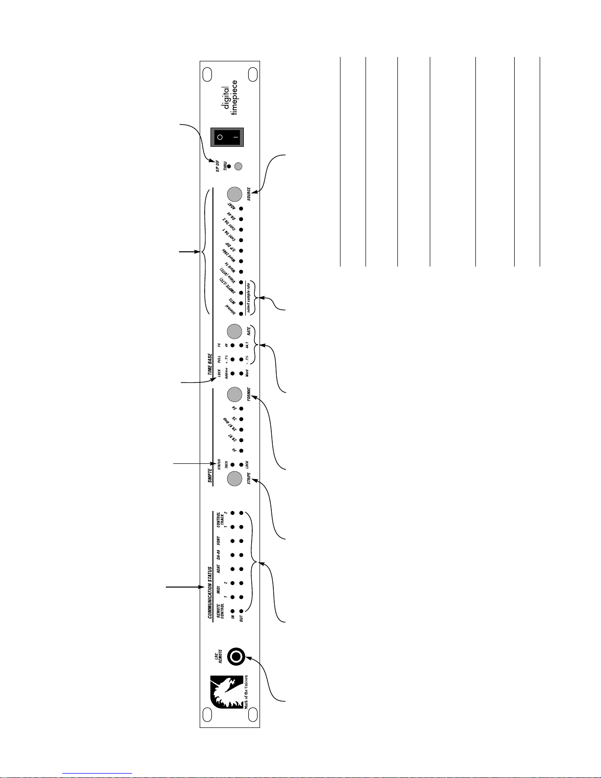
When the S/PDIF THRU button is pushed in, the LED
illuminates and the Digital Timepiece passes digital
audio signal from its S/PDIF IN to its S/PDIF OUT jack.
The TIME BASE section of the front
panel is where you choose which
components of your system are the
The LOCK indicators (A ddress and Word) glow
steadily when the Digital Timepiece has
successfully achieved and is maintaining
The Digital Timepiece cannot slave to an incoming
S/PDIF signal when the THRU button is engaged.
When the THRU button is released (turned off), the
Digital Timepiece can slave to an incoming S/PDIF
signal. In addition, it continuously generates its own
time base master and the time code
(address) master. For example, if you
choose video+SMPTE mode, video
blackburst (house sync) could be the
time base master, while SMPTE time
lockup to the current address and time base
sources. The Address LED glows when the
Digital Timepiece is successfully reading and/
or generating time code. The Word LED glows
when the Digital Timepiece’s digital audio
S/PDIF signal on its S/PDIF output jack, to which a
connected device can slave.
code (LTC) from a VTR could be the
address master.
phase loop engine has stabilized and is
currently generating or locking to a time base.
Press the SOURCE button repeatedly t o choose the over all time base and time code
(address) source. There are 28 possible settings but only 11 LEDs, so many time
base modes are indicated by a combination of 2 or 3 illuminated LEDs (indicated
with a / sign below). Below is a brief summary of each mode:
Time base mode Explanation
When one of these first
four LEDs is illuminated,
the Digital Timepiece
controls the global word
clock rate as determined
by the word rate settings
of six word clock rates as
■ 48 kHz
shown by these four LEDs.
The six possible rates are:
Press the RATE button
repeatedly to choose one
The selected item is both time base and address (time
code) master.
Video serves as the time base master and the other
chosen source (Internal, MT C, LTC, or VITC) is the address
(time code) master.
Internal
MTC
SMPTE (LTC)
Video / Internal
Video / MTC
Video / SMPTE (LTC)
on its front panel (at left).
All other time base modes
derive the word clock rate
from their respective
external time base source.
■ 48 pull-up (+1%)
■ 48 pull-down (-1%)
■ 44.1 kHz
■ 44.1 pull-up
■ 44.1 pull-down
(from the 9-pin deck or from house sync) is the time
base master and the 9-pin deck is address master (via
its 9-pin connection).
An external word clock device serves as the time base
master and the other chosen source (Internal, MTC, LTC,
control track, ADAT or DA-88) is the address (time code)
master.
Video (VITC)
Video SONY 9-pin This mode is indicated by a blinking Video LED. Video
This word clock rate
setting only needs to be
Word 1x / Internal*
set manually here when
you have selected the
Digital Timepiece, time
code or video as the time
Word 1x / MTC*
Word 1x / SMPTE (LTC)*
Word 1x / control track 1 and 2
Word 1x / ADAT
* Also available in
Word 256x format
for Pro Tools systems.
base master (with the
TIME BASE controls on the
right). Other time base
An external word clock device serves as the time base
master. The external word clock master device and the
Digital Timepiece are both resolved to video, so that
Word 1x / DA-88
Word 1x / video / Internal
Word 1x / video / LTC
Word 1x / video / MTC
modes derive the word
clock rate from their
respective external time
base source.
both devices can achieve accurate video frame lock. The
address master can be Internal, LTC, MTC, VITC or 9-pin.
master and the Digital Timepiece is the address (time
Word 1x / video / VITC
Word 1x / video / Sony
S/PDIF / Internal An external S/PDIF device serves as the time base
code) master.
The selected item is both time base master and address
(time code) master.
Control track 1 or 2
ADAT
DA-88
The TACH light blinks once
per second when the Digital
Timepiece is either generat-
ing or converting time code.
The LOCK light glows when
the Digital Timepiece has
successfully achieved and is
maintaining lockup to
external time code.
0 Front P anel Quick Refer ence
The COMMUNICATION
STATUS lights blink when
data is sent to and from
the Digital Timepiece.
Time code appears as a
steady glow. Polling and
“handshaking” messages
appear as flickering.
For time base modes
that require you to
manually choose
the SMPTE time
code frame rate,
If the Digital Timepiece is
currently set to Internal
mode (as shown by the
TIME BASE LED to the
right) — which makes it
The output status lights
show when data is being
sent to each output
destination. When the
Digital Timepiece is idle
Connect an Alesis LRC
or LRC-compatible
remote control here.
press the FORMAT
button repeatedly to
the address (time code)
master, pressing the
(not generating or
converting time code),
choose the desired
rate. However, for
time base modes
STRIPE button makes it
begin generating time
code (as well as all other
the output lights will
flicker about once per
second as the Digital
that make the
Digital Timepiece
sync formats) at
0:00:00:00, unless you
Timepiece continuously
checks for devices
follow external time
code, this setting is
made automatically
have used the ClockWorks
console software to set
any SMPTE start time you
connected to it. If a
device is present, the
Digital Timepiece contin-
by the Digital
Timepiece, which
senses the frame
rate of the incoming
wish. If an external source
is currently chosen as the
address master, pressing
this button won’t do
ually checks for its
current frame location to
make sure it is in sync
with the Digital
time code.
anything.
Timepiece. When the
Digital Timepiece is
generating or converting
time code, the LEDs will
glow continuously.
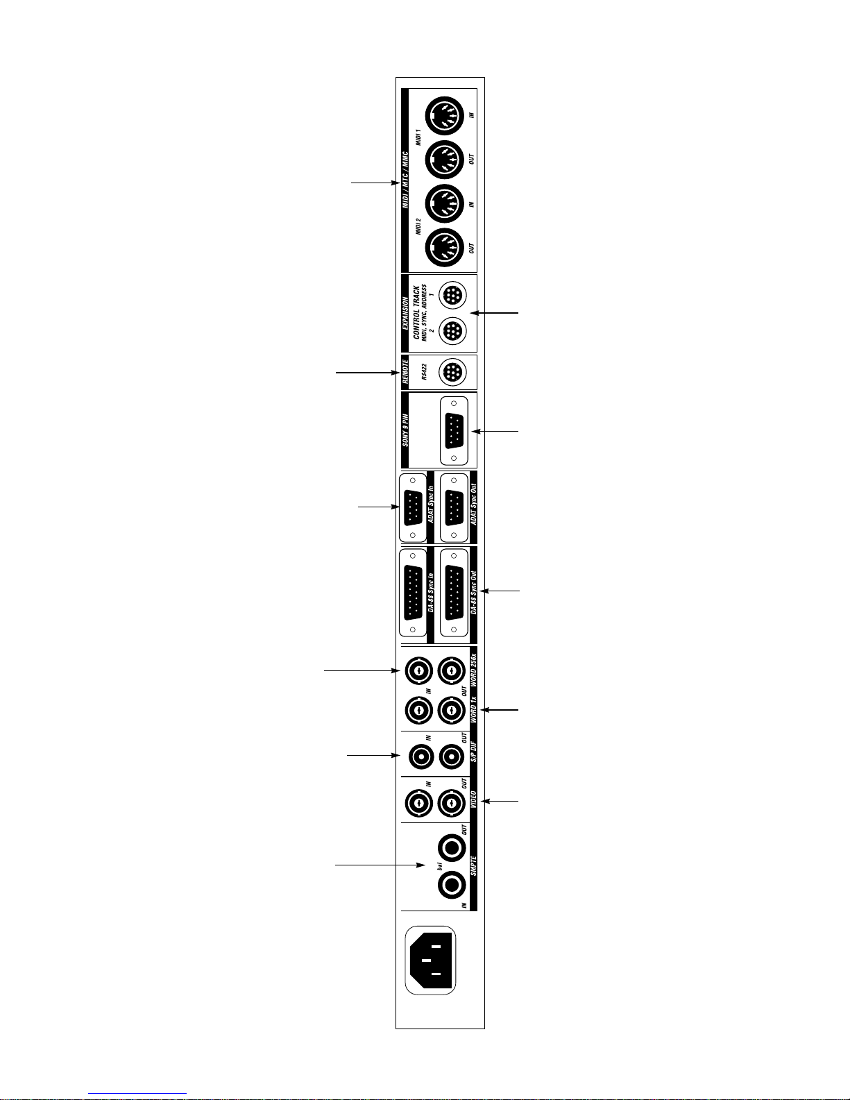
■ A MIDI interface connected to a
Use the MIDI ports to connect the following
types of MIDI devices:
To connect the Digital
Timepiece directly to a Macin-
tosh computer (without a
The Digital Timepiece must either be at the
beginning or end of a chain of ADATs.
Accordingly, never connect both the Sync In
computer (not necessary if the Digital
Timepiece is connected to a Macintosh
via the RS422 REMOTE port)
separate MIDI interface),
connect this RS422 port to the
modem or printer port of the
and Sync Out sockets at the same time. Only
use one or the other. In most circumstances,
you will want the Digital Ti mepiece to be the
compatible device
■ Any MIDI Machine Control (MMC)
■ Any MMC controller, such as a JL Cooper
Macintosh. This allows the
Digital Timepiece to talk to an y
MIDI software, and it acts as a
sync master over your ADAT (or chain of
ADATs). If so, connect the Digital Timepiece’s
ADAT Sync Out port to the Sync In of your
CuePoint™ or CS10™
that you would like to slave t o MT C (MIDI
Time Code)
■ Any MIDI device or computer software
standard 1 MHz MIDI interface.
The Digital Timepiece even
allows MIDI devices connected
to its MIDI ports to communi-
ADAT, and, if you have others, chain them off
of the first ADAT as directed in your ADAT
manual. The ADAT Sync In port allows the
Digital Timepiece to be the slave of an ADAT
cate with MIDI software
(or at the end of a chain of ADATs), which, in
■ Any MIDI instrument, such as a synthe-
sizer, sampler, drum machine, etc.
CONTROL TRACK is the Digital
Timepiece’s own, proprietary
synchronization format. It
carries all three components of
synchronization: word rate,
address and transport infor-
mation. Connect any device
that supports it, such as
another Digital Timepiece.
running on the computer.
Connect a SONY 9-pin
compatible video
tape recorder (VTR)
here. This connection
allows the Digital
Timepiece to be
either a master of or
slave to a SONY 9-pin
compatible video
deck or other device.
turn, could be controlled by a BRC. Note that
all of this applies to other ADAT-compatible
decks as well, such as the Fostex RD-8.
0 Rear Panel Quick Ref erence
WORD 256x is Digidesign’s
own special flavor of word
clock. It w orks with Digidesign
systems only — ones that
have word clock jacks with a
label on them something like:
If you want to slave the
Digital Timepiece to an
S/PDIF device, connect
the master S/PDIF signal
to the Digital Timepiece
S/PDIF IN connector. An
The SMPTE IN and OUT
jacks are standard tip/
ring, balanced +4dB
connectors for SMTPE
LTC. Connect a LTC
source, such as a
■ “Slave clock”
■ “Superclock”
■ “Word 256x”
S/PDIF device can be
slaved to the Digital
Timepiece via the S/
PDIF output connector,
multitrack tape deck
or the audio from a
VTR, to SMTPE IN. The
SMPTE OUT jack can go
Compatible systems include
Pro T ools™, Pro T ools Project™
(formerly called “Session 8”)
and Pro Tools III™.
which continuously
generates S/PDIF sync,
unless the THRU button
is pushed in on the front
panel, in which case it
to any destination,
such as a stand-alone
hard disk recorder, a
time code track on a
tape deck, etc.
The Digital Timepiece must either be at the
beginning or end of a chain of DA-88s.
Accordingly, never connect both the Sync In
and Sync Out sockets at the same time. Only
use one or the other. In most circumstances,
you will want the Digital Ti mepiece to be the
sync master over your DA-88 (or chain of
DA-88s). If so, connect the Digital
Timepiece’s DA-88 Sync Out port to the Sync
In of your DA-88, and, if you have others,
chain them off of the first DA-88 as directed
in your DA-88 manual. The DA-88 Sync In
port allows the Digital Timepiece to be the
slave of an DA-88 (or at the end of a chain of
DA-88s), which, in turn, could be controlled
by a RC-848. Note that all of this applies to
other DA-88 compatible decks as well, such
as the Tascam DA-38.
Connect any standard
digital audio word
clock device, such as a
stand-alone hard disk
recorder, to these
connectors. Do not
connect Digidesign
hard disk recording
systems here. For
Digidesign systems,
use the WORD 256x
connectors instead.
simply passes input to
its output.
To VIDEO IN, connect any video
source, such as house sync black-
burst or a VTR. To VIDEO OUT,
connect any video destination,
such as a video monitor or any
device that requires video sync.
The Digital Timepiece ’ s time c ode
burn-in display and other video
display options are viewed from
its video output.
The Digital Timepiece has a built-
in video sync generator. For
important information about
how the video sync generator
interacts with the Digital
Timepiece’s synchronization
features, see chapter 9, “Working
with Video” (page 67).

CHAPTER
3 Installation
OVERVIEW
Because the Digital Timepiece supports a wide
range of devices, this installation guide is divided
into sections. Each section expl ains how t o connect
an individual type of gear to the Digital Timepiece.
It may also briefly discuss other important
information, such as special considerations or
operating requirements you need to know to
successfully operate the gear with the Digital
Timepiece.
For sections that do not apply to you (you don’t
own that specific piece of equip men t, f or exam pl e),
just skip over them.
Computers . . . . . . . . . . . . . . . . . . . . . . . . . . . . . . . .14
Digital Multitrack tape decks . . . . . . . . . . . . . . . .16
Word Clock Devices . . . . . . . . . . . . . . . . . . . . . . . .22
S/PDIF devices. . . . . . . . . . . . . . . . . . . . . . . . . . . . .24
Video . . . . . . . . . . . . . . . . . . . . . . . . . . . . . . . . . . . . .27
If your device isn’t specifically mentioned
If you have a device that is not specifically
mentioned in this installation guide, read the
general description of each device category to see if
your device falls in that category. If it does, the
general description p rovided — tog ether with your
device’s instructions — should be enough to get it
working with the Digital Timepiece.
Also check these other resources for late-breaking
information about new devices that can be used
with the Digital Timepiece:
■ Inserts included with this manual
■ Our Web site (www.motu.com)
SMPTE time code devices. . . . . . . . . . . . . . . . . . .28
MIDI Time Code devices. . . . . . . . . . . . . . . . . . . .29
Alesis LRC. . . . . . . . . . . . . . . . . . . . . . . . . . . . . . . . .29
MMC control surfaces . . . . . . . . . . . . . . . . . . . . . .30
13
COMPUTERS
The Digital Timepi ece serves as an exc ellen t wa y to
synchronize MIDI software and computer-based
digital audio workstations with the rest of the gear
in your studio. If your software supports MIDI
Machine Control (MMC), you can control the
transports of everything from your computer. If
your software supports MMC record functions,
you can accomplish basic recording tasks from
your computer, too, such as arming tracks,
recording on them, and even recording automated
punch-ins.
The Digital Timep iece does not r equir e a com put er
to perform its basic synchronization duties. A
computer does provide one important advantage:
it allows you to run the Digital Timepiece’s control
panel software, called ClockWorks™, which gives
you access t o features in the Digital Timep i ec e tha t
are not available from the front panel.
For information about installing and using the
Digital Timepiece software console, called
ClockWorks™, see the ClockWorks User’s Guide
that accompanies this guide.
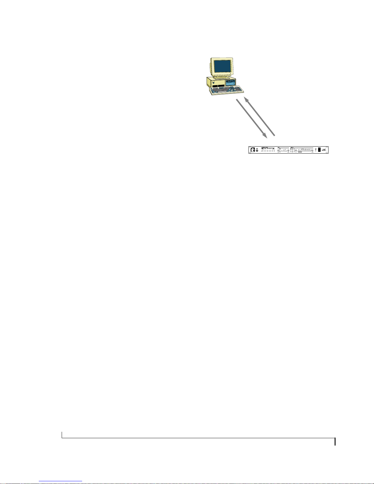
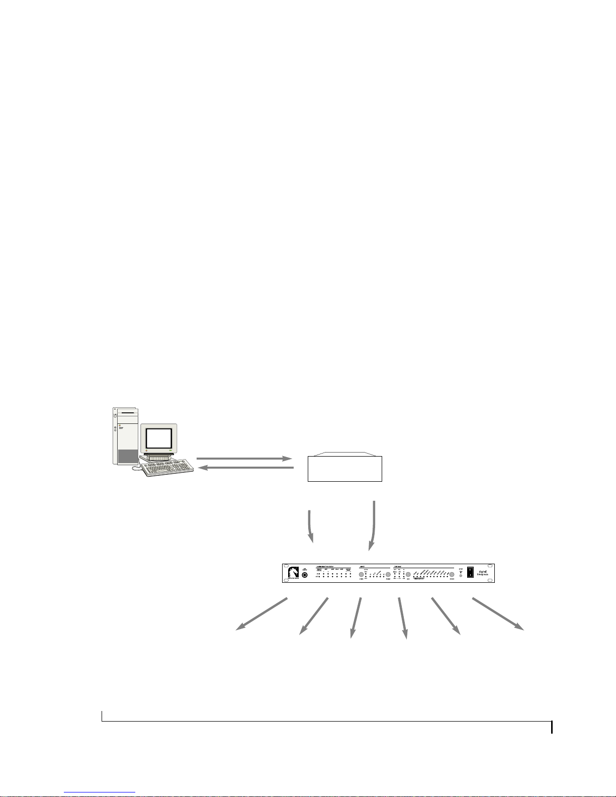
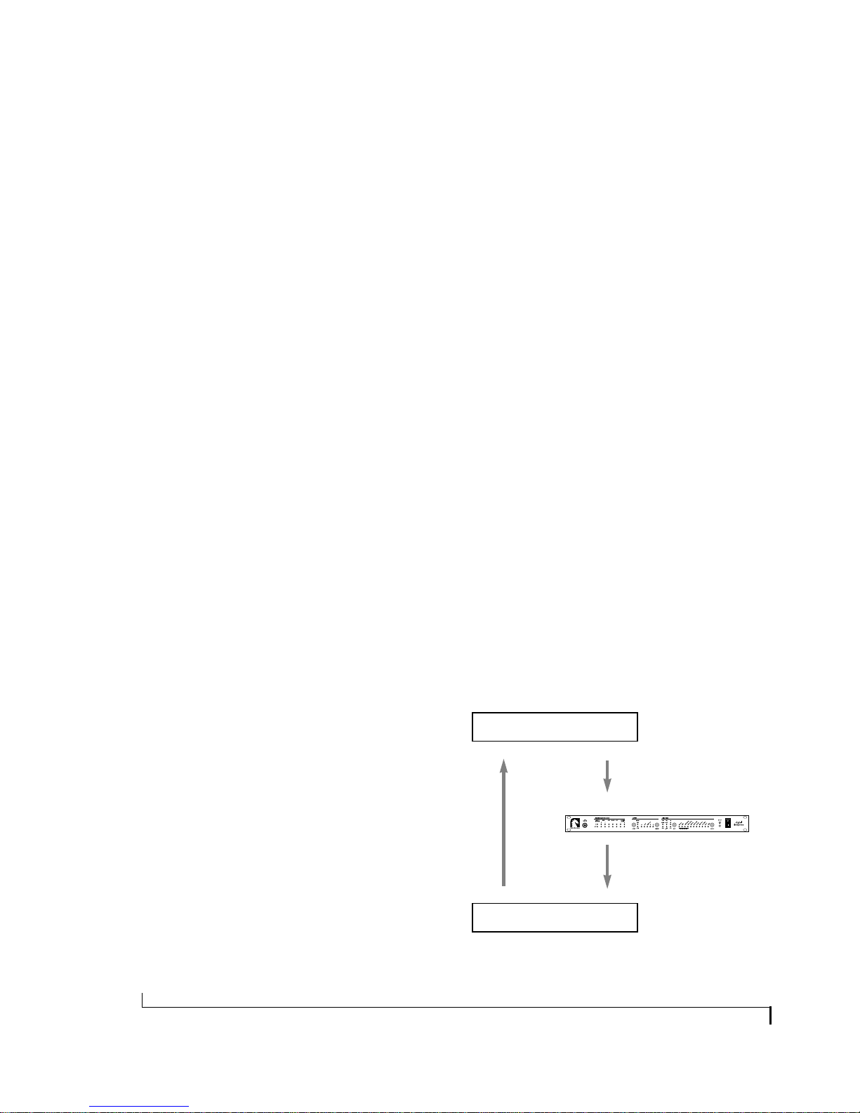
How it works
Comput er software co mm unicat es with the Digital
Timepiece via either MIDI Time Code (MTC),
MIDI Machine Control (MMC) or both
(Figure 3-1). Software on the computer slaves to
MTC generated by the Digital Timepiece.
Conversely, software that supports MMC can send
MMC transport commands (play, stop, rewind,
locate, etc.) to the Digital Timepiece.
MIDI software
and/or
digital audio workstation
MIDI Machine Control
(MMC)
Figure 3-1: How a computer software communicates with the Digital
Timepiece.
MIDI Time Code
(MTC)
Digital Timepiece
Connecting a Macintosh
There are two different ways you can connect a
Macintosh to the Digital Timepiece:
■ With a standar d RS422 (ci r cular “DIN-8”) cable
and the Digital Timepiece’s built-in serial port
(Figure 3-2)
■ With MID I cabl es and a separa te MID I in te rface
(Figure 3-3)
There are no performance or operational
advantages either way, so the choice is a practical
one. If you have an available serial port and a
DIN-8 serial cable that will reach from the
comp uter to the Digital Timep i ece, it may be more
convenient to connect directly, thus avoiding time
code routing issues in your MIDI interface. Also, if
you use OMS, there are additional practical
considerations that you may want to consider. See
chapter 11, “Digital Timepiece & OMS” (page 79)
for details.
☛ Digital audio workstations that involve
additional hardware installed inside the computer
or connected externally to the computer may or
may not require these MIDI connections in lieu of
connections made directly between the hardware
and the Digital Timepiece.
14
INSTALLATION
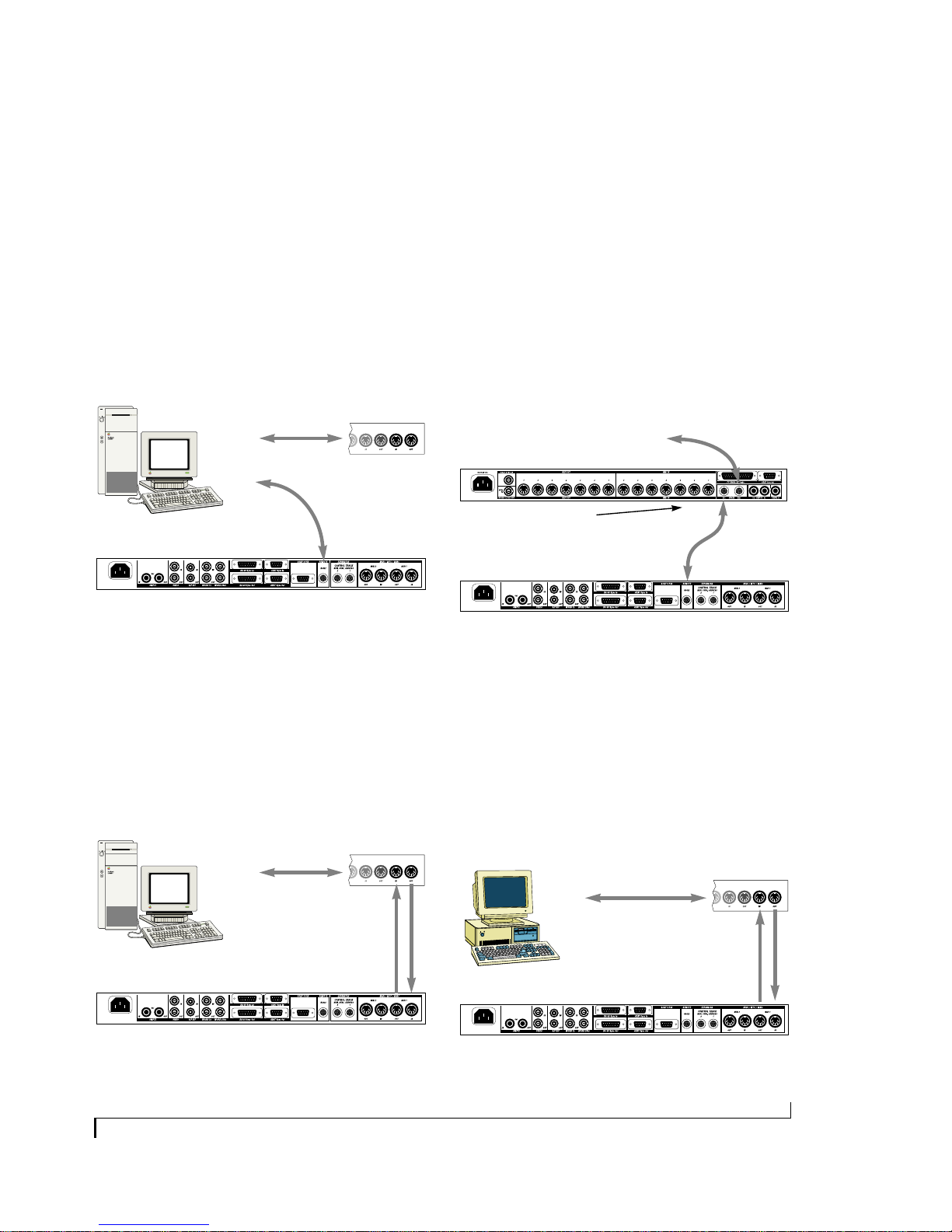
Connecting via the Mac’s modem or printer port
When you connect the Digital Timepiece directly
to the Macintosh’s modem or printer port with a
standard RS422 (DIN-8) cable (Figure 3-2), it acts
as a standard 1 MHz MIDI interface. Set your
MIDI software to 1 MHz on the serial port that th e
Digital Time Piec e is conn ected to , an d also be sure
that your sequencer or DAW software has the
ability to receiv e MT C from tha t serial port. U se th e
other serial port for your MIDI interface, if you
have one.
Macintosh
computer
Digital Timepiece
modem
port
printer
port
Serial
cables
(RS422)
MIDI interface
If you have a MIDI Timepiece AV
The Digital Timepiece’s synchronization
capabilities far exceed those of the MIDI
Timepiec e AV. Ther efo re, you will probably want to
make the Digital Timepiece handle synchronization chores while the MIDI Timepiece AV takes
care of MIDI processing and networking. For
optimum flexib ility, connect the Digital Timepi ece
to your Mac using a combination of the
connections in Figure 3-2 and Figure 3-3. Or
connect it to the Net port of the MIDI
Timepi ece AV.
To modem port on Mac
MIDI Timepiece AV
Using the MTP’s front panel LCD
controls, set the ‘Net’ port to ‘Mac’ in
the in the ‘Global Hardware’ menu.
Digital Timepiece
Net port
Serial cables
(RS422)
Mac port
Remote port
Figure 3-2: An example of how to connect a Macintosh computer to
the Digital Timepiece via their serial ports.
Connecting via a MIDI interface
When you connect the Digital Timepiece to a
Macintosh via a MIDI interface (Figure 3-3), make
sure that the interface is programmed to route
MTC from the Digital T im epiec e to the M acin tosh.
For example, some interfaces connect to both Mac
serial ports and dedicate one serial port entirely to
time code.
Macintosh
computer
modem
port
Digital Timepiece
Figure 3-3: An example of how to connect a Macintosh computer to
the Digital Timepiece via a MIDI interface.
Serial
cable
MIDI interface
MIDI
cables
Figure 3-4: Connecting a Digital Timepiece to the Net port of a MIDI
Timepiece AV.
Connecting an IBM-PC or compatible
The Digital Timepiece connects to a PC like any
standard MIDI device: via MIDI cab les and a MIDI
interface (Figure 3-5). Connect MIDI OUT to IN
and IN to OUT as shown. If the W indow s driver fo r
your interface provides a special sync port for
MIDI Time Code (most of them do), make sure
your MIDI software is properly addressing it.
MIDI interface
Parallel
port
IBM PC/compatible
computer
Digital Timepiece
Figure 3-5: An example of how to connect a PC or compatible
computer to the Digital Timepiece via a MIDI interface.
Printer
cable
MIDI
cables
INSTALLATION
15
DIGITAL MULTITRACK TAPE DECKS
This section explains how to use the Digital
Timepiece with modular digital multi-track
(MDM) tape recorders such as the following:
■ Alesis ADAT and ADAT XT
■ Tascam DA-88 and DA-38
other MMC controller). The Digital T i mep iece h as
many of the same capabilities as a BRC, making it
unnecessary for basic synchronization and MMC
remote control of ADATs. The Tascam DA-88
synchronizes with other devices via an SY-88 addon card. See “ABS time versus SMPTE offset with
an SY-88” on page 18 for details.
■ Fostex RD-8 and CX-8
■ Panasonic MDA-1
■ SONY PCM-800
■ Other devices that support the ADAT sync
protocol, such as the Darwin hard disk recorder
from E-mu Systems
ADATs and DA-88s have their own proprietary
synchronization format, which is supported
directly by the Digital Timepiece. MDMs from
other manufacturers have, in some cases, adopted
either the Alesis or Tascam sync format. One
example is the F ostex RD-8. The RD-8 has adopted
the Alesis ADAT sync forma t and, as a res ult, can be
connected directly to the Digital Timepiece in the
same fashion as an ADAT. Check with the
manufacturer of your device for compatibility.
Modular digital multi-track systems have their
own means of chaining multiple units and
synchronizing them with single-sample accuracy
to form, in effect, on e large system tha t functions as
a whole. The Digital Timepiece synchronizes
multiple unit systems just as easily and effectively
as a single unit. In fact, the connections and
procedures for the Digital Timepiece are the same
for single- and multiple-unit systems. The Digital
Timepiece can even sync ADATs and DA-88s with
each other with single-sample accuracy.
Modular digital multi-tracks also provide a way to
synchronize to SMPTE time code. For example,
ADATs and ADAT XTs require an Alesis BRC to
synchronize to SMPTE or to follow MMC
transports commands from com put er software (or
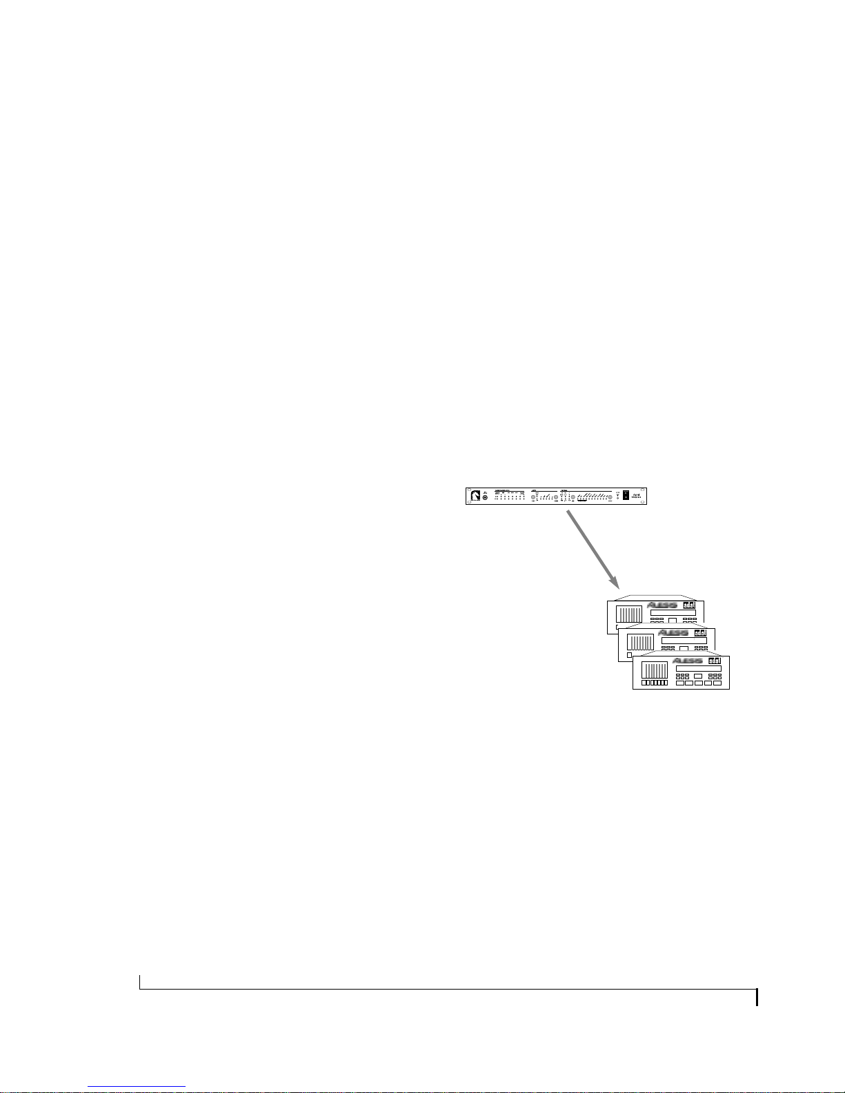
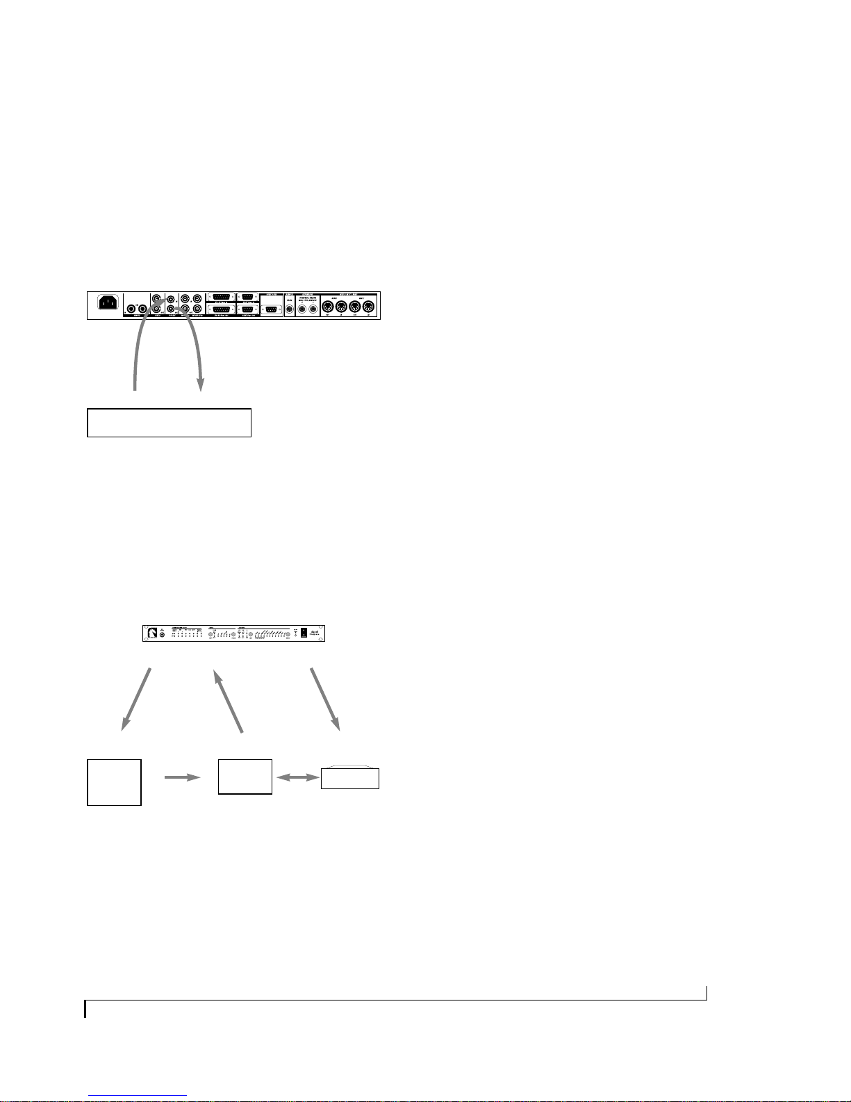
How proprietary synchronization works
AD ATs, DA-88s and any other devices that s up port
the ADAT o r DA-88 proprietary sync protocols are
connected directly t o the Digital Timepiece via the
ADAT and DA-88 Sync ports. This connection
provides both a sample-accurate time base and
frame-accurate address information (Figure 3-6).
In addition, the multi-track recorders to be either
master of or slave to the Digital Timepiece.
Digital Timepiece
proprietary,
sample-accurate
time base
and
address
Figure 3-6: How modular digital multi-track recorders like the ADAT,
DA-88, DA-38 and RD-8 synchronize with the Digital Timepiece.
ADAT, DA-88, DA-38, RD-8
or other
modular digital multi-track
Refer t o the sections bel ow f or specific inf orma tion
about each device, including important considerations if you are al so using an Alesis BR C or Tascam
SY-88 sync card.
New MDM systems are frequently being
introduced. If you have a device other than the
ones discussed in the following sections, contact
Mark of the Unicorn technical support as
described in “Technical Support” on page 98.
16
INSTALLATION
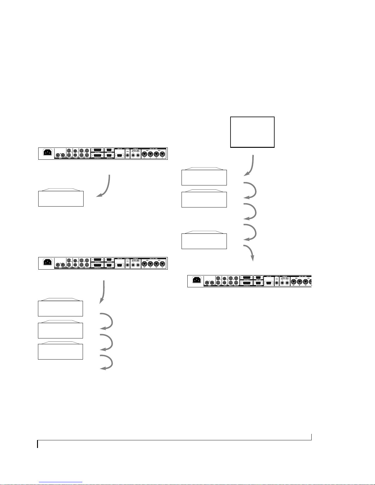
Connecting ADATs as slaves
In most circumstances, you will want the Digital
Timepiece to be the sync master over your
ADAT(s). If so, connect the Digital Timepiece’s
ADAT Sync Out port to the Sync In of your first
ADAT using the sync cable supplied with the
ADAT as shown in Figure 3-7. Don’t worry about
setting the ADAT device ID: the Digital Timepiece
sets it automatically.
Digital Timepiece
Connecting the Digital Timepiece as a slave
If you hav e an Alesis BRC, an d y ou wan t t o use it as
your master control surface, you will need to
connect the Digital Timepiece as the last device in
your ADAT chain, as shown below in Figure 3-9,
with the BRC as the master of the chain.
BRC
Sync Out
ADAT
Sync
Out
ADAT
Sync In
port
Figure 3-7: Connecting an ADAT as a slave to the Digital Timepiece.
ADAT sync cable
If you ha ve sev eral ADATs, y ou can c hain the r est of
them to the first one as shown in Figure 3-8.
Digital Timepiece
ADAT
Sync Out port
ADATs
Sync In
Sync Out
Sync In
Sync Out
ADAT
sync cables
ADATs
Sync In
Sync Out
Sync In
Sync Out
etc.
Sync In
Sync Out
Digital Timepiece
Figure 3-9: Connecting a slaved Digital Timepiece as the last device in
an ADAT chain.
ADAT
sync cables
ADAT
Sync In
Sync In
Sync Out
etc.
Figure 3-8: Connecting multiple ADATs.
INSTALLATION
17

WORKING WITH THE TASCAM DA-88
There are sev eral ways to connect the DA-88 to the
Digital Timepiece, depending on whether you are
running the DA-88 under ABS time or SMPTE
time (while under the control of a Tascam SY-88
sync card). The next section discusses ABS time
versus SMPTE offset with an SY-88 card.
Connecting a DA-88 as an ABS slave
This type of sync can be done without an SY-88
sync card. The Digital Timepiece controls the
DA-88. For example, from your computer
sequencer, you can shuttle the Digital Timepiece,
which in turn controls the DA-88. In this scenario,
the DA-88 operates under ABS time only.
ABS time versus SMPTE offset with an SY-88
The Tascam DA-88 can measure time in two ways:
■ absolute time (also called ABS time)
■ SMPTE time with an offset (start frame)
Absolute time is a measurement of actual elapsed
time since the beginning of the tape, where the
beginning of the recordable portion of the tape
(immediately after the tape leader) is zero. The
front panel o f the D A-88 disp lays ABS time, as does
the MMC/Sync window in the Digital Timepiece’s
ClockWorks software. For example, if you start
recording at the beginning of the tape and record
for 20 minutes, the ABS time display on the front
panel of the DA-88 would display approximately
0:20:00:00.
If your Tascam DA-88 has an SY-88 sync card
installed inside, the SY-88 card provides you with
the ability to stripe (recor d) SMPTE time code o n a
special “sub-code” track on the tape. Once a tape
has been striped in this manner, the SY -88 car d can
then read the time code on sub-code track and
generally pla y, locate, and otherwise cue the D A -88
according to the time code, rather than ABS time.
For example, you could stripe the tape starting at a
time other than zero — a common situation when
working with audio f or picture — s uch as one h our
and five minutes (01:05:00:00). You can then
choose the offset option on the front panel of the
D A -88 t o disp lay SMPTE time instead of ABS time
in the DA-88’s front-panel counter. If you then
record f or twen ty minute s starting at the beginning
of the tape, the DA-88 counter would read
approximately 1:25:00:00.
If you need to reference the DA-88 and Digital
Timepiece to an external time code source, use one
of the SY-88 related scenarios described in the
following sections.
This scenario provides sample-accurate sync
between the DA-88 and the Digital Timepiece.
When the Digital Timepiece has control over one
or more DA-88s via the DA-88 sync connectors
(using ABS time), it must cue in three-second
intervals to maintain sample-accurate sync. For
example, if you cue the Digital Timepiece to 5
minutes and 2 sec on ds fro m the transport con tr ol s
in your sequencer, and then start playback, the
Digital Timepiece (and all devices under its
control) will begin playing at the nearest 3-second
interval (5 minutes, 3 seconds in this example).
If you are do in g d etailed work for which this threesecond interval is not acceptable, use one of the
SY-88-related sync scenarios described in the
following sections.
18
INSTALLATION
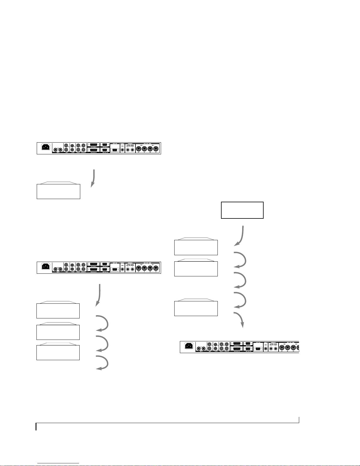
In this scenario, connect the Digital Timepiece’s
DA-88 Sync Out port to the Sync In of your first
DA-88 using the sync cable supplied with the
D A -88 as sho wn in Figure 3-10. I f you ha v e a single
DA-88, make sure the device ID selector on the
‘System’ card on its rear panel is not set to zero. If
you ha ve a c hain of D A -88s, make sure that none of
them are set to zero, and also make sure that each
unit has a unique ID setting.
Digital Timepiece
DA-88
Sync
Out
DA-88
Any device ID except 0
Figure 3-10: Connecting a Tascam DA-88.
DA-88 sync cable
Sync In
port
If you have several DA-88s, you can chain the rest
of them to the first one as shown in Figure 3-11.
Note tha t you can c onnect both AD AT s and D A -88s
at the same time (not pictured).
Digital Timepiece
DA-88
Sync Out port
DA-88s
Device ID 1
Sync In
Sync Out
DA-88
sync cables
Connecting the Digital Timepiece as ABS slave
In this scenario, the DA-88 serves as the time base,
address, and transport master. You control the
Digital Timepiece, along with everything else
attached to the Digital Timepiece, from the
transport controls on the DA-88 itself. This
scenario provides sample-accurate sync between
the DA-88 and the Digital Timepiece.
There may be so me situa tions in which y ou w ant t o
slave the Digital Timepiece to your DA-88 instead
of the other way aro und. For example, if yo u ha v e a
Tascam RC-848 controller, and you wan t to use it as
your master control surface, you will need to
connect the Digital Timepiece as the last device in
your DA-88 chain, as shown below in Figure 3-9,
with the 848 as the master of the chain.
RC-848
Sync Out
ADATs
Sync In
Sync Out
Sync In
Sync Out
etc.
Sync In
Sync Out
ADAT
sync cables
Device ID 2
Device ID 3
Figure 3-11: Connecting multiple DA-88s.
INSTALLATION
Sync In
Sync Out
Sync In
Sync Out
etc.
Note: if you are using
house sync, it should not
be fed to the DA-88s in this
scenario. House sync
should be fed to the Digital
Timepiece instead.
ADAT
Digital Timepiece
Figure 3-12: Connecting a slaved Digital Timepiece as the last device
in a DA-88 chain. In this example, the RC-848 is master of the chain.
Sync In
Make sur e yo u set the R C-848 ID to zer o (0) so that
it powers up as the master of the chain. Also make
sure the DA-88s in the chain are set to unique IDs.
The Digital Timepiece itself has no ID in this
scenario.
19
Using a DA-88 with an SY-88 sync card as the
SMPTE time code master
If you woul d like t o use the SMPTE time code track
on a DA-88 deck equipped with an SY-88 card,
then the DA-88 cannot operate as a slave to the
Digital Timepiece. Instead, the DA-88 acts as the
master and the Digital Timepiece slaves to it, a
shown below in Figure 3-13. The word clock
connection from the SY-88 card to the Digital
Timepiece is optional, although it is highly
recommended for tighter sync and faster lockup
time.
This scenario requires an SY-88 card. The DA-88/
SY-88 combination serves as the master, feeding
SMPTE time code (LTC or MTC) to the Digital
Timepiece and other devices. You control the
Digital Timepiece, along with everything else
attached to the Digital Timepiece, from the DA-88.
This scenario allows yo u t o sync the DA-88 — and
the Digital Timepiece — to time code from other
sources, such as a video deck, or the time code subtrack on a DA-88 tape.
DA-88/SY-88 as SMPTE and word clock master
This scenario is identical to the SMPTE-only
scenario just discussed, except that you also feed
word clock from the SY-88 card into the Digital
Timepiece, in addition to SMPTE time code, as
shown below in Figure 3-13. This produces faster
lock-up times and tighter sync than the SMPTEonly scenario above.
MMC compatible
sequencer or audio
software
bi-directional MIDI
for MMC and MTC
MMC remote control setup notes
To control this entire rig from your computer:
1. Set the Machine ID on the SY-88 car d using
the first four DIP switches at location S2 on
your SY-88 card. Refer to your DA-88
manual for details.
2. Connect a MIDI Out from your MIDI interface to the MIDI In on the SY-88 card so
software can send MMC commands to the
SY-88 card.
3. Be sure to feed MTC back to the computer,
either from the SY-88 MIDI OUT port or
from the Digital Timepiece (but not both!).
4. Make your software send MMC commands
with the same ID you gave the SY-88 (not
the Digital Timepiece). See “Controlling a
DA-88/SY-88 with Performer” on page 72.
Figure 3-13: To use the time code track on a DA-88 equipped with an SY-88 sync c ar d , the DA-88 serves as the time code master. In this setup ,
it also serves as the time base master. The Digital Timepiece slaves to the word clock and SMPTE it receives from the DA-88. The MMC remote
control from the computer as shown here is optional. Figure 3-14 on page 21 shows this setup with everything referenced to house sync.
Digital Timepiece
time base mode:
Word 1x/LTC
Various forms of word clock and SMPTE time code distributed by the Digital Timepiece to other devices.
DA-88 with SY-88 Sync Card
SY-88 Card
SMPTE out
(LTC or MTC)
SMPTE IN
(LTC or MTC)
Digital Timepiece
DA-88
Word clock out
Word 1x IN
DA-88/SY-88 setup notes
1. If you are using MTC, make sure the SY-88 is
programmed to send MTC by checking the SY-88
card’s S2 location DIP switches (on the board
itself). The 8th switch should be “On”.
2. Make sure the Digital Timepiece’s frame rate and
sample rate match the DA-88/SY-88. (Note: the
DA-88 sample rate is visible on the front panel; the
frame rate can be set by depressing the up/down
arrows simultaneously. Use the up/down arrows
to change the frame rate, if necessary. Depress
DISPLAY & down arrow to exit.)
3. T he SY-88’s rear panel MODE DIP switches must be
set to enable MIDI Machine Control. All switches
should be in the down position, except for #2
20
INSTALLATION
Using house sync with the Digital Timepiece
and a DA-88/SY-88 (“Triple-sync”)
If you would like to use the SMPTE “sub code”
track on a DA-88 equipped with an SY-88 card as
the master address source for your rig, and you
would also like to use house sync video as a
timebase for everything, connect the DA-88 to the
Digital Timepiece as shown below in Figure 3-14.
In this setup, both the SY-88 card and the Digital
Timepiece resolve to house sync. In addition, the
Digital Timepiece resolves to the word clock
generated b y th e SY-88 card. The SY-88 card serves
as the time code address master source.
This scenario is identical to the o ne on the pr evious
page (Figure 3-13), except for the video feed to
both the DA-88 and the Digital Timepiece.
Of all the SY-88-r ela ted (no n-ABS) sync scenarios,
this one prod uc es the tight est l ock-u p betw een th e
Digital Timepiece and the DA-88.
You can contr ol the transpo rts of the entire rig (via
the SY-88 card) from one of several possible
transport control sources:
■ The transport buttons on the front panel of the
DA-88
■ An RC-848 controller connected to the DA-88
■ Computer software that has been set up to
control the SY-88 card via MIDI Machine Control
Because the Digital Timepiece is so flexible, you
can use various sources for time code, video, and
word clock. For example, you co uld feed S MPTE to
the SY-88 card and Digital Time pi ece fro m a video
deck that is also referenced to house video, such
that the video deck is the transport/address mast er.
Controlling a DA-88/SY-88 from Performer
You can trigger the entire rig shown in Figure 3-13
or Figure 3-14 from Performer. For step-by-step
directions, see “Controlling a DA-88/SY-88 with
Performer” on page 72.
Check the DA-88/SY-88 setup notes in
MMC compatible
sequencer or audio
software
Check the MMC remote control setup notes in
Figure 3-13 for additional important info.
Figure 3-14: To use the sub code track on a DA-88 equipped with an SY-88 sync card as the address master while using house sync as the time
base, connect the DA-88/SY-88 to the Digital Timepiece as shown here. Notice that the time base mode for the Digital Timepiece is Word 1x/
video/LTC (or Word 1x/video/LTC). The Digital Timepiece can resolve to both the house sync and the word clock from the DA-88/SY-88, which is
also resolved to house sync, while at the same time following the SMPTE time code (LTC or MTC) from the SY-88 card.
INSTALLATION
bi-directional MIDI
for MMC and MTC
Digital Timepiece
time base mode:
Word 1x/video/LTC
or
Word 1x/video/MTC
Various forms of word clock and SMPTE time code distributed by the Digital Timepiece to other devices.
Figure 3-13 for additional important info.
DA-88 with SY-88 Sync Card
Video Sync In
SY-88 Card
SMPTE out
(LTC or MTC)
DA-88
Word clock out
Word 1x INSMPTE IN (LTC or MTC)
Video IN
House Sync
Video Generator
Digital Timepiece
21
WORD CLOCK DEVICES
Word clock is a timing reference for digital audio
devices. Word clock supplies common timing to
multiple devices so that they can be synchronized
with one another. We call a device that supports
word clock — i.e. it has word clock connectors on
it — as a word clock device. Here are a few
examples:
■ Digital mixers
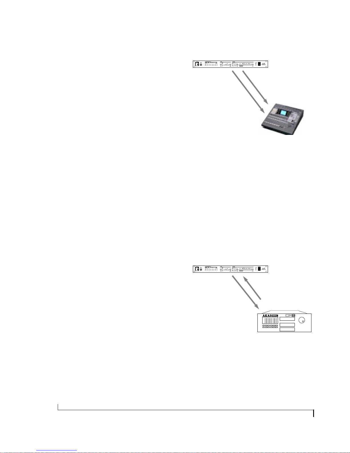
Digital Timepiece
Word clock
Time code (LTC or MTC)
word clock device
Yamaha 02R digital mixer
■ Stand-alone hard disk recorders
■ Computer-based digital audio workstations
■ Computer audio cards
The Digital Timepi ece sup ports two diff eren t wo rd
clock formats: Word 1x and Word 256x. Word 1x is
an industry standard format and is supported by
all devices except several systems made by
Digidesign. Digidesign systems have their own
word clock format, Word 256x, which they refer to
as superclock, slave clock or word 256x. Always
connect Digidesign hardware to the WORD 256x
connectors on the Digital Timepiece. Connect all
other word clock devices to the WORD 1x
connectors.
How it works
When synchronizing two word clock devices, one
acts as the master and the other serves as a slave.
The slaved device follows the master to maintain
sample-accurate synchronization.
Figure 3-15: How word clock devices synchronize with the Digital
Timepiece. In this example, the Digital Timepiece is both the word
clock (time base) master and address (time code) master.
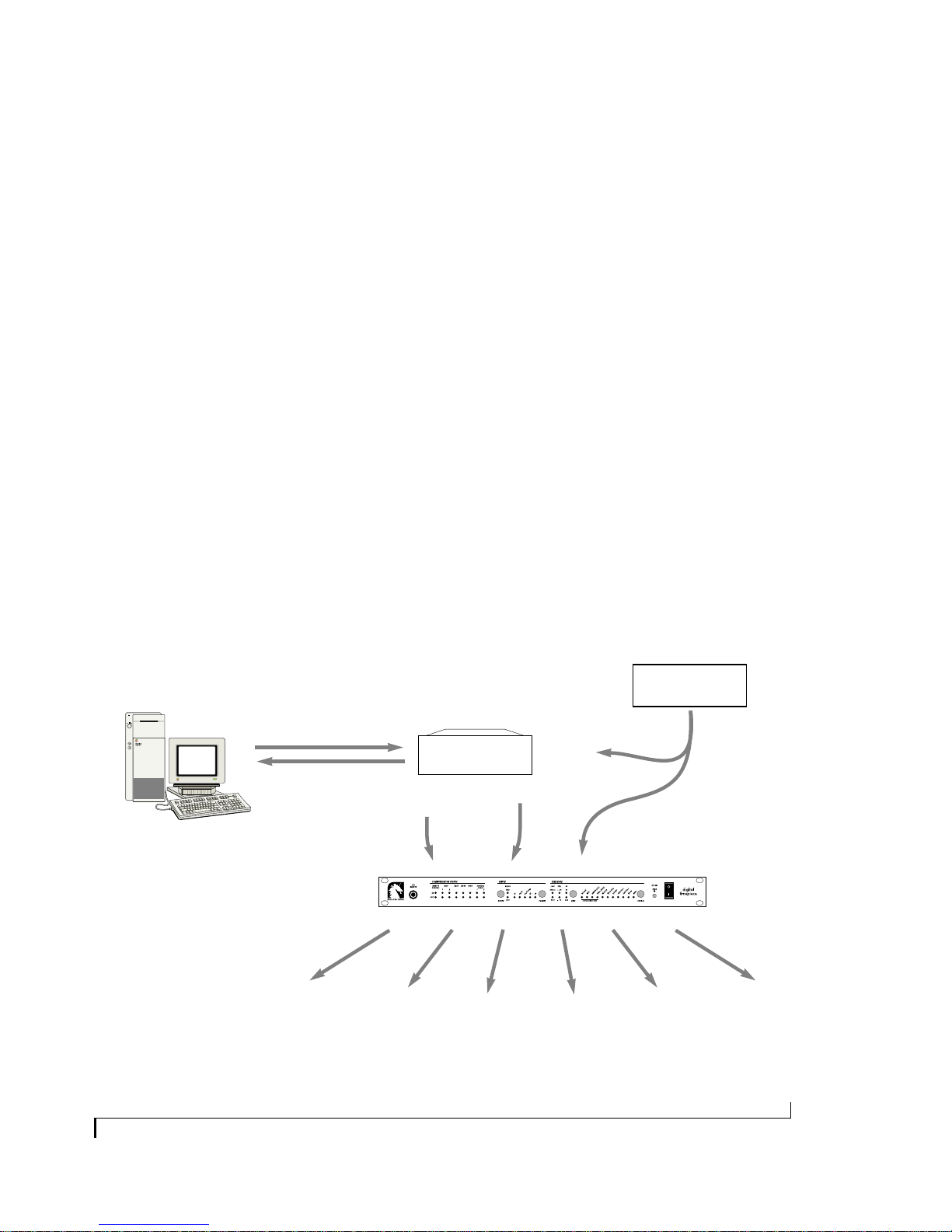
Inter estingly , though, the wor d clock master d evice
does not necessarily have to be the address master.
A word clock sl ave can be an address master, while
the word clock master provides the overall time
base. In the example shown in Figure 3-16, the
Digital Timepiece is the word clock master, while
the Akai DR8 hard disk recorder is the time code
master. This setup would allow you to control the
transports of everything from the DR8 front panel
(or a transport control surface connected to the
DR8).
Digital Timepiece
Word clock Time code (LTC or MTC)
word clock device
(Akai DR8 hard disk recorder)
Word clock is a time base referen ce o nly, pro viding
an accurate measurement of the passage of time
and the speed at which sam ples s hould g o b y. Word
clock carries no address (time code) information
(e.g. “we’re at 1:05:33:14”). Therefore, word clock
by itself is not enough to synchronize two devices.
Time code is also required so that each device
knows where to go in time when you tell it to cue,
play, record, stop and chase. An example is shown
below in Figure 3-15.
22
Figure 3-16: In this example, the Digital Timepiece is the word clock
(time base) master and the Akai DR8 hard disk recorder is the address
(time code) master. This allows you to synchronize the DR8 with other
digital audio devices connected to the Digital Timepiece, while at the
same time controlling the transports of everything from the DR8 (or a
control surface connected to the DR8).
INSTALLATION
Connecting a word clock device as slave
In most situations, you’ll want to connect your
word clock device as a slave to the Digital
Timepiece as shown below in Figure 3-17.
Digital Timepiece
word 1x
SMPTE
SMPTE
Word clock device
Figure 3-17: Connecting a word clock device. In this example, SMPTE
time code is being fed to the word clock slave device via the Digital
Timepiece’s LTC SMPTE output. Alternately, you could feed MIDI Time
Code (MTC) from the Digital Timepiece’s MIDI OUT.
OUT
IN
OUT
word clock
IN
Connecting multiple word clock devices
If you ha v e mor e than o ne w or d cl ock device, there
are several possibilities for connecting them to the
Digital Timepiece. First, the Digital Timepiece
actually provides two w ord clock o utputs: a W ORD
1x OUT and a WORD 256x OUT , and it is possible
to use both at the same time. For example, you
could connect a stand-alone hard disk recorder to
the word 1x output and a Digidesign Pro Tools™
system to the word 256x output. (Just remember,
only Digidesign hardware will work with the 256x
output.)
But what if you already have a device connected to
the 1x word clock output, such as a hard disk
recorder, and you’d like to connect a second word
clock device, such as a digital mixer? In this
scenario, y o u can try chaining the second device to
the first, connecting the word clock output of the
first to the word clock input of the second. Keep in
mind, however, that some devices don’t support
this very well. For best results, try to keep the cable
lengths as short as possible.
INSTALLATION
23
S/PDIF DEVICES
S/PDIF is an industry standard format for
transferring stereo digital audio from one device to
another. While many devices on the market
support S/PDIF, the term S/PDIF device as used in
this discussion refers to a device that has no other
way of synchronizing digitally with other devices.
Examples of this kind of device are:
■ Digidesign Audiomedia I, II and III cards
■ DAT decks
Devices that hav e S/PDIF c onnector s, bu t also ha ve
word clock connectors, ADAT sync connectors, or
other means of digital audio synchronization,
should be incorporated into a Digital Timepiece
system using these other sync formats.
How S/PDIF sync works
When synchronizing tw o S/PD IF d evices, one acts
as the master and the other serves as a slave. The
slaved device follows the master to maintain
accurate synchronization that won’t drift.
S/PDIF is similar to word clock in the sense that it
is a time base reference, providing an accurate
measurement of the passage of time and the speed
at which samples should go by. S/PDIF can also
contain embedd ed address inf ormation (e .g. “we’re
at 1:05:33:14”). However, many S/PDIF devices,
including most DAT decks, do not support
embedded time code. In order to support as wide a
range of devices as possible, the Digital Timepiece
does not support embedded S/PDIF time code
either . Instead, it uses the S/P DIF sam p le clock as a
time base and relies on time code (SMPTE time
code or MIDI time code) to make the S/P DIF
device chase, locate and play in sync with the
Digital Timepiece. An example is shown in
Figure 3-22 on page 26.
S/PDIF devices cannot be chained.
S/PDIF thru
S/PDIF differs from word clock because it is not
just a synchronization format: it consists of actual
digital audio signal, which can be recorded from
one device to another. As a result, the Digital
Timepi ece has a S/PD IF THRU butto n on the fro n t
panel that allows the Digital Timepiece to become
transparent and pass any a udio signal it recei ves on
its S/PDIF IN port directly to its S/PDIF OUT po rt.
When the THRU button is pushed out, the Digital
Timepiece “swallows” incoming S/PDIF signal. If
the Digital Timepiece is currently set to its S/PDIF
time base mode, it will also slave to the S/P DIF
signal that it swallows. When the THRU button is
pushed in, the THR U LED on th e fron t panel lights
up and the Digital Timepiece ignores whatever it
receives on its S/PDIF input, passing the signal
through, unaltered, to its S/PDIF output as shown
in Figure 3-18. The Digital Timepiece cannot slave
to S/PDIF input when S/PDIF THRU is engaged.
This feature is supplied as a convenience, so you
don’t ha ve to swap cables for different situations. If
you want to slave the Digital Timepiece to an S/
PDIF device, r elease the THRU button. I f yo u wan t
to pass the device’ s S/PDIF signal to another device
connected to the Digital Timepiece’s S/PDIF Out,
push the THRU button in.
S/PDIF device A
S/PDIF In
S/PDIF Out S/PDIF In
S/PDIF device B
Figure 3-18: An example of bidirectional communication between
two S/PDIF devices. When Digital Timepiece’s S/PDIF THRU button is
pushed in (turned on), device A can send signal to Devic e B. When the
S/PDIF Out
S/PDIF In
S/PDIF Out
Digital Timepiece
S/PDIF THRU
turned on
(button pushed in)
24
INSTALLATION
S/PDIF THRU button is pushed out (off), the Digital Timepiece
“swallows” the signal from Device A. The Digital Timepiece can slave
to Device A only when THRU is turned off.
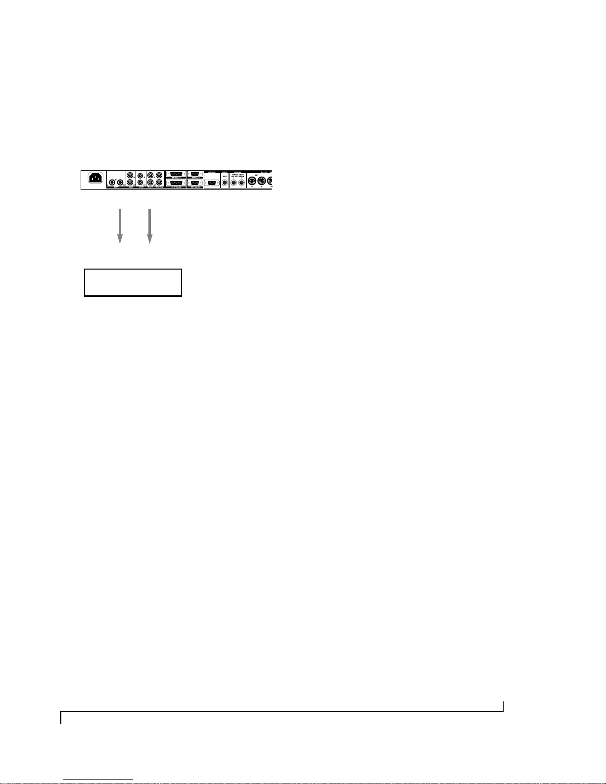
Connecting S/PDIF devices
The S/PDIF connections you make to the Digital
Timepiece depend on what devices you have. Here
are a few examples.
Digital Timepiece
S/PDIF In S/PDIF Out
If you have two S/PDIF devices, you can connect
them as shown in Figure 3-18 on page 24. But only
Device B can be slaved digitally (via S/PDIF) to the
Digital Timepiece.
Example: Digidesign’s Audiomedia card
Digidesign’s Audiomedia card serves as a useful
example for how you can use the Digital
Timepiece’s S/PDIF synchronization capabilities.
The Digital Timepiece’s S/PDIF sync feature helps
solve two problems for Audiomedia™ I, II or III
users: drift and digital transfers to and from ADAT
and other systems.
S/PDIF InS/PDIF Out
S/PDIF device
Figure 3-19: Connecting a single S/PDIF device to the Digital
Timepiece.
If you have S/PDIF device, such as an Audiomedia
card, and another device that is slaved to the
Digital Timepi ece, such as an AD AT or DA-88, and
you would like to do S/PDIF transfers between
them, you would need to connect them like this.
Digital Timepiece (Internal mode)
S/PDIF
Out
S/PDIF
In
Audiomedia
Sync mode:
Figure 3-20: Connecting an Audiomedia card bidirectionally with a
DA-88 via the Digital Timepiece. The Digital Timepiece is the word
clock and time code master. When recording from DA-88 to Audiomedia, engage S/PDIF THRU on the Digital Timepiece front panel
(push it in). When rec ording fr om Audiomedia to DA-88, disengage S/
PDIF THRU (push it out). This same scenario could be used for ADAT
(with an Alesis AI-1 converter, which connects optically to ADAT).
S/PDIF
Out
Digital
S/PDIF
S/PDIF
In
S/PDIF
Out
IF-88AE
In
converter
DA-88
Sync Out
TDIF-1
I/O
DA-88
Sync In
DA-88
The drift problem
The first problem is drift. If you have an
Audi omedia card, you are probab ly running it with
a digital audio sequencer or a Digidesign software
package like P r o Tools™ or Sessio n™. But yo u have
probably discovered that when you are slaving the
software to external time code, long portions of
audio (i.e.audio regions that are longer than a
minute or so) can drift out of sync with time code.
This is because the Audiomedia card triggers
regions at the proper time during playback, but
once they start, they’re on their own, playing at a
rate determined by the Audiomedia card’s own
internal clock. Because the Audiomedia card’s
clock is not resolved to external time code, the
audio inevitably drifts over time. To address this
problem, most Audiomedia-compatible programs
offer a software synchro niza tio n f ea tur e, where the
software slaves to external time code and then
drives the Audiomedia hardware. B ut this f eatur e is
undesirable because it actually adds or removes
samples as needed to stay in sync with external
time code — not exactly a high-fidelity solution.
Another work-around is to chop lengthy audio
regions int o small pieces — no t exactly co n venie nt.
INSTALLATION
25
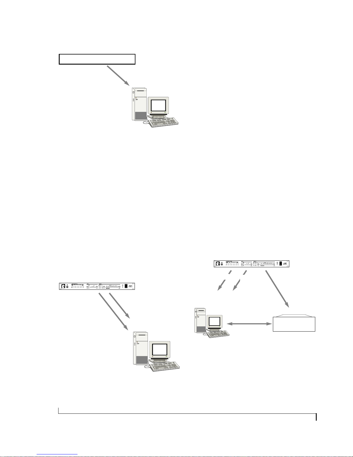
MIDI Time Code source
MIDI Time Code
Figure 3-21: Before the Digital Timepiece, was available Audiomedia
would either run on its own internal clock or be driven by software
synchronization. The results were either drift or audio distortion.
Macintosh with Audiomedia card
running audio software
The Digital Timepiece solves these drift problems
by supplying the Audiomedia card with a stable,
external word clock time base (via S/PDIF output
from the Digital Timepiece to the S/PDIF input of
the Audiomedia card.), along with resolved time
code, which is fed as MIDI Time Code (MTC) to
the software running the card. The Audiomedia
card slaves in perfect sync with the Digital
Timepiece via its S/PDIF input, which
continuously resolves the word clock time base.
And since the Digital T im epiece is providing these
synchronization services to all other devices as
well, the Audiomedia card can stay perfectly in
sync with all other devices, too.
Digital audio transfers
The second problem for Audiomedia users has
been successfully transferring audio digitally
between Audiomedia and other devices that are
slaved to their own word clock master. Before the
Digital Timepiece, this type of transfer would be
inconvenient because you would have to
temporarily make the other device slave to the
Audiomedia card for the transfer, which often
involves physically plugging and unplugging
cables. But the Digital Timepiece solves this
problem because both Audiomedia and the other
device can be connected to and slaved to the
Digital Timepiece at all times, even during digital
audio transfers between them.
A schematic example is shown in Figure 3-23
between the Audiomedia card and the Tascam
D A-88 via the Tascam IF-88AE format c on verter. A
similar arrangement could be made with Alesis
ADAT and Alesis AI-1 format converter.
The connections required for Figure 3-23 are
shown in Figure 3-20.
Digital Timepiece
Digital Timepiece
S/PDIF word clock MIDI Time Code
Macintosh with Audiomedia card
running audio software
Figure 3-22: The Digital Timepiece supplies stable, resolved S/PDIF
word clock to the Audiomedia card, along with MIDI Time Code.
26
S/PDIF word clock
Macintosh with Audio-
media card running
audio software
Audiomedia sync mode
set to ‘Digital’
Figure 3-23: An example of making digital audio transfers to and
from a Digidesign Audiomedia card. In this example, both the Audiomedia card and the Tascam DA-88 multitrack recorder are slaved to
the Digital Timepiece. Transfers between the Audiomedia card and
the DA-88 are made possible by the Tascam IF-88AE format converter
(not shown).
MIDI
Time
Code
bidirectional
S/PDIF transfers
via
Tascam IF-88AE
format converter
DA-88 Sync
DA-88
INSTALLATION

VIDEO
The Digital Timepiece can synchronize to any
video signal, including blackburst (“house sync”)
or a video feed from a standar d video tape rec ord er
(VTR). It can read and lock to VITC. It has video
display features, including a SMPTE burn-in,
which it superimposes over the video signal sent
from its VIDEO OUT connector. Its VIDEO OUT
can be either a thru from the input or video black,
which can be generated by the Digital Timepiece’s
built-in video generator. In either case, you can
choose whether or not to include the Digital
Timepiece’s video overlay display.
Connecting video devices
Connect any video source to the VIDEO IN of the
Digital Timepiece. Typical sources include:
■ House sync
■ VTR output (with or without VITC)
■ Video distribution amplifier
Connect any video destination t o the VID EO OUT
of the Digital Timepiece. Most often this will be a
video monitor, so you can see the time code burn
in and other video display features of the Digital
Timepiece. It could also be a video deck.
Accessing the Digital Timepiec e video f eatur es
The video features in the Digital Timepiece can be
accessed using ClockWorks™, the Digital
Timepiece’s console software. See your
ClockWorks manual for details.
The advantage of house sync video
House sync video pro vides faster locku p times. F or
details, see “Getting faster lockup time with house
sync (blackburst) as a time base” on page 35.
Using the Digital Timepiece video generator
The Digital Timepiece has a built-in video sync
generator. For important information about how
the video sync generator interacts with the Digital
Timepiece’s synchronization features, see
chapter 9, “Working with Video” (page 67).
INSTALLATION
27
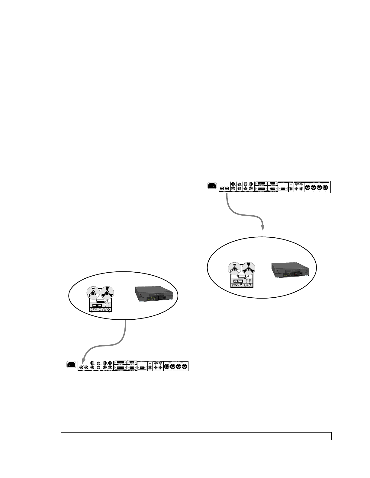
SMPTE TIME CODE DEVICES
The Digital Timepiece is a SMPTE time code
converter and generator. As a converter, it reads
incoming longitudinal SMPTE time code (LTC)
from a time code sour ce . As a generator, it produces
time code that is recorded to a destination.
The Digital Timepiece is also a VITC reader and
generator. For information, see “Video” on
page 27.
When making the SMPTE time code connections
described in the following sections, d o not pass the
signal through any type of signal processing
equipment. Use shielded quarter-inch audio
cables.
Connecting a SMPTE time code destination
Connect the Digital Timep iece ’s SMPTE OUT port
to the SMPTE time code input of any destination
device that accepts SMPTE time code as shown in
Figure 3-25.
For example, time code can be recorded on an
outside track of a multitrack tape recorder so that
everything can subsequently be synchronized to
the multitrack. Other examples of a SMPTE time
code destination are syst ems that ha ve th e ability to
slave to SMPTE time code, such as stand-alone
hard disk recording systems, digital audio
workstations, or automated mixing consoles.
Connecting a SMPTE time code source
Connect any SMPTE time code source, such as the
SMPTE time code track on an analog multitrack
tape deck, to the SMPTE IN port on the Digital
Timepiece as shown in Figure 3-24. (For
information abou t recor ding time code tracks with
the Digital Timepiece, see “Striping SMPTE” on
page 90.)
Analog audio tape recorder Video tape recorder
REC
PLAY
Examples of a SMPTE
time code source
Audio or SMPTE out
Shielded, quarter-inch audio cable
SMPTE in
Digital Timepiece
SMPTE out
Shielded, quarter-inch audio cable
SMPTE or Audio in
Examples of a SMPTE
time code destinations
Analog audio tape recorder
Figure 3-25: Connecting a SMPTE time code destination.
Video tape recorder
PLAY
Digital Timepiece
REC
Figure 3-24: Connecting a SMPTE time code source.
28
INSTALLATION
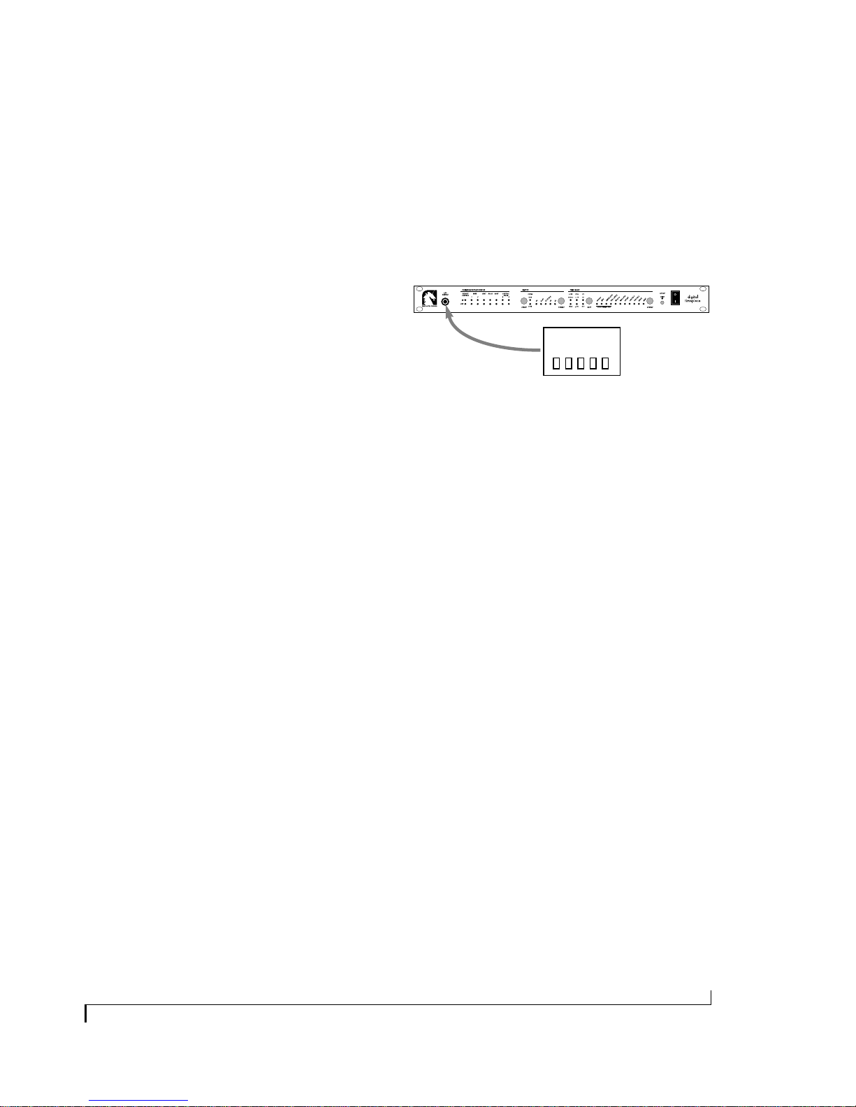
MIDI TIME CODE DEVICES
The Digital Timepiece provides MIDI Time Code
(MTC) to any device (or computer software) that
requires it. MTC is transmitted from the Digital
Timepiece’s two MIDI OUT ports, as well as the
RS422 REMOTE port (which would normally be
connected to a Macintosh computer).
ALESIS LRC
The LRC REMOTE jack on the front panel of the
Digital Timepiece can serve as an input for the
Alesis LRC™ remote controller, or any device that
emulates th e LR C, such as the Fost ex M odel 8312™
controller.
To slave a device to MTC generated by the Digital
Timepiece, connect the MIDI OUT of the Digital
Timepiece to the MIDI IN on the device. For
computer connections, see “Computers” on
page 14.
Digital Timepiece
LRC REMOTE jack
Alesis LRC
or similar device
Figure 3-26: Connecting an Alesis LRC remote controller.
INSTALLATION
29
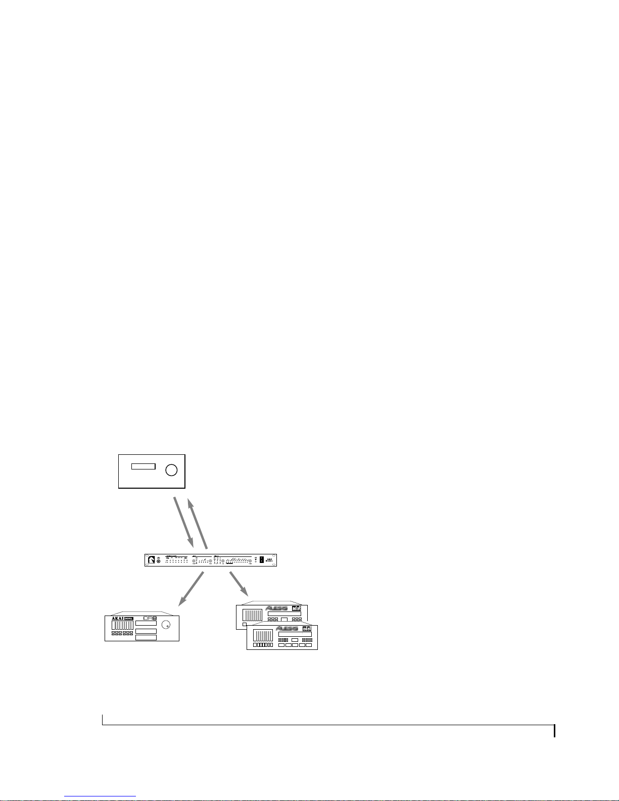
MMC CONTROL SURFACES
MMC control surfaces are hardware devices that
provide gen eric MMC co n tro ls, such as transports,
a jog/shuttle wheel, and time code display of some
kind, record-enable buttons and often a host of
other programmable controls.
Example of such devices are the JL Cooper
CuePoint™ and CS-10™ workstations.
How it works
MMC controller devices issue MIDI Machine
Control commands that control the Digital
Timepiec e. F or exam ple, the transpo rt button s on a
MMC controller send MMC commands such as
play, stop and locate, to the Digital Timepiece,
which follows them, generating sync for all
connected devices. the Digital Timepiece also
sends Time Code back to the controller so that its
SMPTE counter can provide you with a running
update of time code — And so the controller
knows where the Digital Timepiece is at any time.
You are, in effect, triggering the Digital Timepiece
from your MMC controller, while the Digital
Timepiece is actually the time code master.
MMC controller
Time Code (LTC or MTC)
MIDI Machine Control (MMC)
Digital Timepiece
Connecting a MMC controller
You need to establish bidirectional MIDI
communication between the Digital Timepiece
and the MMC con troller (fo r MMC — and MT C, if
you are using it instead of LTC). To do so, you can
connect the MMC co n tr oller dir ectly t o the Digital
Timepiece MIDI IN and MIDI OUT jacks.
Alternately, you could connect both the Digital
Timepiece and the MMC controller to your
multiport MIDI interface and route MMC
internally from the controller to the Digital
Timepiece.
Some controllers may require an LTC connection
for time code instead of MTC. If so, connect
SMPTE OUT from the Digital Timepiece to LTC
IN on the controller.
From the standpoint of achieving MMC transport
control over the Digital Timepiece, the above
preparations ar e all yo u need. Ther e may, of course,
be other preparations necessary in the controller
itself.
The factory default MMC device ID for the Digital
Timepiece is one (1). Make sure you program the
transport controls on the controller for ID 1. Note,
however, that the Digital Tim epiece uses a 1-based
ID numbering scheme (from 1 to 128), whereas
your MMC controller may use a zero-based
numbering scheme (from 0 to 127). If so, the
Digital Timepiece ID setting in your MMC
controller should be zero (0), i.e. the lowest ID
value possible.
Other devices
slaved to the
Digital Timepiece
Figure 3-27: When the Digital Timepiece is the time code address
master (i.e. it is in one of its Internal time base modes), you can
control it (and everything connected to it) directly from a MMC
hardware controller.
30
MMC record commands
Some MMC controllers have the ability to send
MMC record commands to MMC devices. For
example, you can rec o r d-ena bl e a track on a MM C
device by pressing a b utt on o n the co ntr oller. Some
controllers let you do more elaborate record
functions, such as set automatic punch-in and
punch-out recording.
INSTALLATION
 Loading...