

Page 1

Unicont SPb Ltd
Analog digital programmable converter
ADPC-101
Technical Documentation
(101-4-30102013)
St. Petersburg
2013
v.4.1
Page 2

Unicont SPb Ltd Technical Documentation ADPC-101
Page 2
Table of Contents
1. GENERAL .........................................................................................................................3
2. DELIVERY SET ...............................................................................................................3
3. PERFORMANCE SPECIFICATIONS ..........................................................................3
4. DEVICE INSTALLATION .............................................................................................5
5. UNIT OPERATION .......................................................................................................11
6. AUXILIARY MODE FOR DISPLAY OF SIGNAL STATUS AT INPUT
TERMINALS. ...............................................................................................................12
7. ADDITIONAL DISPLAYING MODES .......................................................................13
8. MENU FUNCTIONS AND CHANGING OF SETTINGS .........................................13
9. EXAMPLE OF CONNECTING ADPC-101 ................................................................17
10. TRANSPORTATION AND STORAGE ......................................................................18
11. RECYCLING ..................................................................................................................19
12. WARRANTY ..................................................................................................................20
13. DATE OF PACKING .....................................................................................................21
14. ACCEPTANCE DETAILS ............................................................................................21
15. DATE OF COMMISSIONING .....................................................................................21
Page 3

Unicont SPb Ltd Technical Documentation ADPC-101
Page 3
1. General
Thank You for purchasing our ADPC-101 navigation device. Design and production of
this device are developed in compliance with applicable industrial standards for marine use.
This device is mounted on ships with gyrocompasses and logs not capable to generate
current values in NMEA format for navigation equipment needing course and speed data in
digital form.
Device executes the following functions:
Reception of current course value from gyrocompasses with synchro or stepper
interface;
Reception of current speed value from logs with stepper interface or interface on
“closing” contact;
Indication of current speed and course values in built-in display;
Conversion of received data into NMEA-0183 format;
Transmission of converted course and speed data via standard interface (RS-232 and
RS-422/485 ports) to external devices in NMEA-0183 format.
Operating modes of this device are easily tuned by user-friendly menu options and
widely used symbols on keyboard pads.
2. Delivery Set
1. ADPC-101 converter 1 piece
2. Operation manual 1 piece
3. Performance specifications
Types of connected equipment
1. Gyrocompasses:
gyrocompass with synchro type;
gyrocompass with stepper type.
2. Logs:
log with stepper (pulses) type;
log with interface on “closing” contact.
Input signals
1. Gyrocompass:
sine voltage of synchro windings;
voltage pulses (stepper type compass)
voltage up to 350V
frequency up to 500Hz
gyro ratio 360x, 240x, 180x, 90x, 60x, 36x
Page 4

Unicont SPb Ltd Technical Documentation ADPC-101
Page 4
Rate of course variations (during vessel turning) up to 80 degrees/s
2. Log:
voltage pulses (stepper type interface);
“closing” contact
voltage up to 350V
100/200/300/400/500/600 pulses per mile
Input specification
- optoisolated inputs (exclude log with closing contact)
- switching level 3V/6V (switched by jumpers)
Output
1. Ports:
two asynchronous serial interfaces RS-232, RS-422/485
parity no/even/odd
stop bits - 1 or 2
NMEA refresh: 1, 2, 5, 10Hz
2. Output signal format:
- standard line NMEA 0183 with line checksum;
- number of options for line output: 63 (sets by 3 separate options)
3. Format parameters:
Data bit: 8 bit;
Rate, bit/s: 2400, 4800, 9600, 14400, 19200, 28800, 38400, 57600, 76800,
115200, 230400
Indicator
Type LCD with backlighting
Lines 2
Characters 16
Range of measurements
Speed: 0..99.9 knots
Heading: 0..359.9 degrees
Data statement precision
Course value 0.1 degree
Speed value 0.1 knot
Keyboard
3x4, film-type, with upper and lower case.
sound when any key is depressed
function of operator idling
Power supply
12..24 VDC, galvanic isolation
power consumption 150 mA maximum
Page 5

Unicont SPb Ltd Technical Documentation ADPC-101
Page 5
Working temperature -20..+55 °C
Storage temperature -60..+70 °C
Weight 1.5 kg
Overall dimensions 200 x 134 x 64 mm
4. Device installation
Mount unit in easy of access place, for example: vertical wall inside of ship.
Safety precautions
Avoid device sinking in water and water ingress inside device casing.
While disconnecting power supply cable, observe correct procedure for
disconnection of cable contacts, avoid contact with printed circuit board.
Do not use organic solvents during cleaning of device surface to avoid damages of
applied decals.
Prohibited:
to use device in floor-mounted position;
to expose device for mechanical shocks and tensioning of power supply cable;
to use faulty device.
Note:
This device should be mounted at least 1 meter from magnetic compass.
It is recommended to install device in the following order:
remove the device face panel;
firmly secure separated casing without face panel on a vertical wall
route and pass connecting cables from external devices through cable entries;
Arrangement of openings, the spacing between openings and overall dimensions are
indicated in Figure 1.
Caution
The whole equipment being connected to the device must be deenergized for the
period of connection.
Page 6

Unicont SPb Ltd Technical Documentation ADPC-101
Page 6
Figure 1 ADPC-101 mounting dimensions
Input channels
Converter has four cable entries to route wires from external devices inside the device
and to connect them to relevant terminals of terminal strips.
connect cables to terminal blocks of unit
secure the device face panel on mounted casing;
tighten gland seals of cable entries.
Arrangement of terminal strips on the board and purpose of contacts are stated in Figure
2.
Wiring diagram for power supply source, output contacts of gyro compass, log and
consumers of course and speed values in NMEA format are stated on diagram – Figure 3 and
Figure 4.
1. Inputs for gyro compass
Both types of gyro compass, namely synchro and stepper (pulse) type are connected to
the same optically isolated inputs capable to change switching threshold.
Connector J1,
Page 7

Unicont SPb Ltd Technical Documentation ADPC-101
Page 7
Inputs: CS1-, CS1+, CS2-, CS2+, CS3-, CS3+, CSR-, CSR+.
1.1 Synchro type gyrocompass.
Synchro type gyrocompass is connected as follows:
output of 1st winding is connected to contacts CS1+, CS3-;
output of 2nd winding is connected to contacts CS2+, CS1-.
output of 3rd winding is connected to contacts CS3+, CS2-.
output of win ce winding is connected to contacts CSR+, CSR-.
1.2 Stepper type gyrocompass.
Stepper type gyrocompass is connected as follows:
all inputs with sign “-” in designation are connected jointly and further are connected
to a common gyrocompass wire (GND), and compass outputs are connected to relevant inputs
“+” as designated.
2. Inputs for log
2.1 Inputs for log with interface on “closing” contact.
Connector J2
inputs LOG, GND.
2.2 Input for log with stepper type interface.
An input is optically isolated which is capable to change switching threshold.
Connector J2
inputs LOG-, LOG+.
3. Information outputs
Information is relayed through asynchronous serial interface of two types:
RS-232: Connector J3, output TX, common wire GND;
RS-422/485: Connector J3, differential outputs TX- and TX+, common wire GND.
4. Power supply
DC voltage power supply within +12..24 V is applied to connector J3.
Power consumption is 150 mA maximum.
Page 8

Unicont SPb Ltd Technical Documentation ADPC-101
Page 8
Figure 2 Arrangement of terminals on printed circuit board.
To change switching threshold of optically isolated inputs of log and gyro compass, use
DIP-switches J4, J5, J6, J7, J8 (or jumpers). With closed contacts, threshold input voltage is
approximately 6 V and about 3V with open contacts.
J4, J5, J6, J7, J8
or - input voltage is approximately 3V
- input voltage is approximately 6V
J10:
ADPC-101 terminate channel of interface RS-422
ADPC-101 does not terminate channel of interface RS-422
Contacts J9 and JP1 use for programming and never using during exploitation of unit
Page 9

Unicont SPb Ltd Technical Documentation ADPC-101
Page 9
Figure 3 Wiring diagram for synchro type gyrocompass.
Page 10

Unicont SPb Ltd Technical Documentation ADPC-101
Page 10
Figure 4 Wiring diagram for stepper type gyrocompass.
Page 11
Unicont SPb Ltd Technical Documentation ADPC-101
Page 11
5. Unit operation
Caution
Before device commissioning, at first complete installation procedure (see para. 4
“Device installation”) and connections (see p.4 “Device Installation”).
5.1 Device switch on procedure
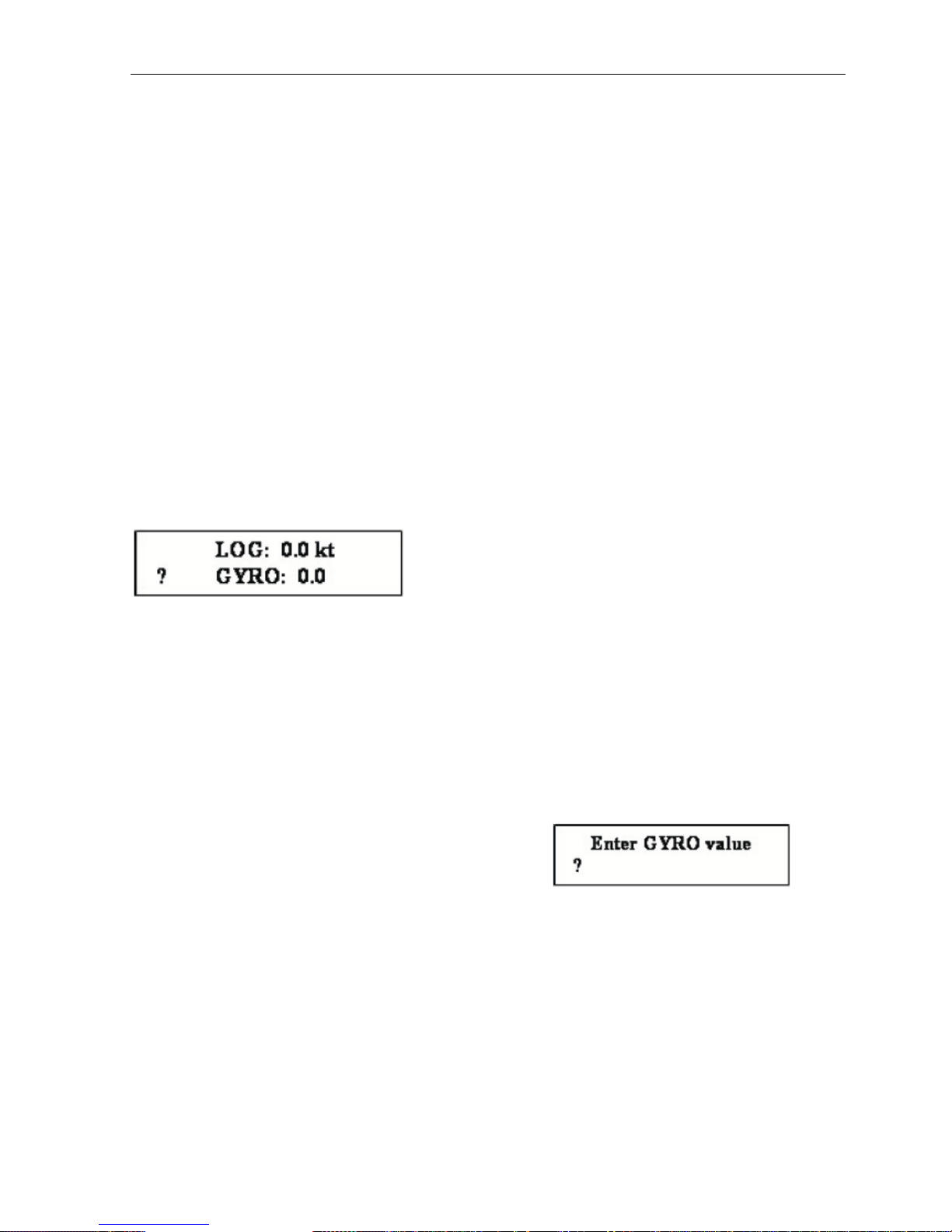
When power is applied, device transfers to review mode of course and speed values;
besides, readings of compass or log values are indicated as zeroes and the signal at converter
output will be disabled. The unit is in standby mode for input of initial course value and
instructions for applicable types of gyrocompass and log. Before input of an initial course value
the alarm system will work.
To achieve correct device operation, select type of compass and log in menu settings
(see p.6 “Menu functions and changing of settings”) and manually enter the current course value
for gyrocompass in use.
Should received values of compass and log are not trustworthy, display with show the
sign ‘?’ (question) at the beginning of relevant line.
- indicator readings during device power ON (mode of
review for current course and speed values).
Note
When the type of compass, namely stepper/synchro is switched over, again enter the
current gyrocompass value.
5.2 Input of initial course value
look at and remember course readings on gyrocompass, which is connected to the
unit;
press on the key [1] on converter keyboard;
there will be a prompt to enter course value:
enter course value by using keys with applied digits and decimal point [.];
Press [ENTER].
The screen returns to a mode for review of current compass course and log speed,
delivery of a sound signal stops .
When it is necessary to edit or delete the last character of entered value one may use the
key [CLEAR].
Keys [.] and [CLEAR] are entered in the upper case and after depression [.] the case
automatically shifts to the lower case and remains in the upper case when [CLEAR] is
depressed.
Page 12
Unicont SPb Ltd Technical Documentation ADPC-101
Page 12
Use key [SHIFT] key to change cases.
The status of case can be visually defined by cursor status:
blinking cursor with illumination of font recticle – lower case;
no blinking (underlining) – upper case.
Caution
All tuned options are stored in ROM memory and remain unchanged after power
ON/OFF. If gyrocompass course readings were changed during converter power OFF period,
enter a new current course value to ensure correct operation of device.
Note
In this mode of tuning one may enter a number with floating point and one decimal
point of decimal fractions. If incorrect value is entered (over 359.9) the number will be ignored.
In case of operator idling and selected option unuse timeout (in position 5s, 10s, 15s,
20s, 25s except for OFF) there will be an automatic exit from input mode to review mode of
course and speed values without changing of any option.
Selected options are preserved only after depression on [ENTER].
After selection of gyrocompass and log types and input of initial course value and
reception of trustworthy data, device starts to transmit NMEA signal to both outputs RS-232 and
RS-422/485 in parallel, once per second.
Example.
For input value “320.3” should press: [1] [3] [2] [0] [SHIFT] [.] [3] [ENTER]
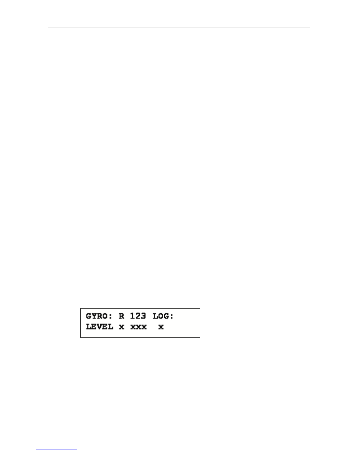
6. Auxiliary mode for display of signal status at input
terminals.
In this mode display shows logical status of signals at device inputs which may be used
during device deployment.
To go into this mode press on [9] key.
logic ‘0’ denotes that a signal level at relevant optically isolated input is below
switching threshold.
logic ‘1’ denotes that a signal level at relevant optically isolated input has exceeded
switching threshold.
123 1st, 2nd, 3rd gyrocompass’s windings
For input of “closing contact” type log
Page 13

Unicont SPb Ltd Technical Documentation ADPC-101
Page 13
logic ‘0’ denotes that the contact is opened
logic ‘1’ denotes that the contact is closed.
The unit will be in this mode until operator initiates exit by pressing on any key.
7. Additional displaying modes
7.1 Total trip displaying
In this mode display shows total trip of a ship after last nulling of total trip counter.
Nulling except after shutdown of converter or with pressing [7] key by operator. After activating
this mode upper string of display with log information changed to string with information about
haul.
To go into this mode press on [F2] key. To go out from this mode press on [F2] key
again.
NMEA data output in this mode does not stop or change.
7.2 Displaying of ROT (rate of turn)
In this mode display shows current rate of turn of a ship. After activating this mode
lower string of display with current heading information changed to string with information
about ROT.
To go into this mode press on [3] key. To go out from this mode press on [3] key again.
8. Menu functions and changing of settings
Press on [F3] key and enter menu of settings. Use [3], [0] keys (up and down) for
scrolling between options.
Use [6], [8] keys (left, right) to select probable option values.
Again press on [F3] key for exit from selected mode. Selected options are stored only
after pressing on [ENTER].
When operator is idling and unuse timeout option is selected (in positions 5s, 10s, 15s,
20s, 25s except for OFF) an automatic exit from the menu is initiated without changes of any
option.
Page 14

Unicont SPb Ltd Technical Documentation ADPC-101
Page 14
8.1 Gyrocompass tuning
8.1.1. GYRO ratio - 360x, 240x, 180x, 90x, 60x, 36x
8.1.2. GYRO sign – direction of compass rotation: positive, negative.
8.1.3. GYRO type – gyrocompass type: selsyn, stepper.
Note
Again enter the current compass value during switching of stepper/ synchro compass
type.
8.1.4. GYRO ref polarity – selection of reference signal polarity:
positive, negative.
as far as synchro type compass is concerned, selection of negative polarity causes
signal inversion and operation for signal edge shift by 180 degrees.
as far as stepper type gyrocompass is concerned, positive polarity corresponds to
high level and negative one to low level, which is used for determination of gyrocompass
working mode.
8.2 Log tuning
8.2.1. LOG pulse/mile – number of pulses per one mile. 100, 200, 300,
400, 500, 600.
Note
If log pulse repetition period at exact moment exceeds data update interval (1s), speed
is computed based on current measurement history following the last log pulse.
Page 15

Unicont SPb Ltd Technical Documentation ADPC-101
Page 15
8.2.2. LOG bounce delay – time for programmable deletion of contact
“bounce”: 10 ms, 20 ms, 30 ms, 40 ms, 50 ms, 70 ms, 100 ms.
8.3 Serial port tuning
8.3.1. COM baudrate – baud rate, bit/s: 2400, 4800, 9600, 14400,
19200, 28800, 38400, 57600, 76800, 115200, 230400.
8.3.2. COM parity – parity bit: NO, EVEN, ODD (no, even, odd).
8.3.3. COM stop bits – number of stop bits: 1 bit, 2 bits.
8.4 Keyboard tuning
Button click – sound click of depressed key: Yes, No.
8.5 Display tuning
DISPLAY REFRESH - refresh frequency of displayed data: 1, 2, 5 and
10 Hz
8.6 Operator idling (timeout) tuning
Unuse timeout – time of automatic OFF for backlighting and exit from menu of
options or input mode in case of operator idling: 5 second, 10 second, 15 second, 20 second, 25
second, OFF.
8.7 Alarm tuning
Alarm – ON, OFF. If option is setted, device is emitted sound when input data from
gyrocompass or lag is incorrect and beginning course value not initialized.
8.8 NMEA tuning
8.8.1. NMEA REFRESH – refresh frequency of output data: 1, 2, 5 and
10 Hz
8.8.2. NMEA ROT fmt – format of output NMEA line with current ROT
(rate of turn) information:
Disabled - output of ROT information is disabled
TIROT - $TIROT,x.x,A*cs
HNROT - $HNROT,x.x,A*cs
8.8.3. NMEA GYRO fmt – format of output NMEA line with current
heading value:
Disabled - output of heading value is disabled
AGHDT - $AGHDT,x.x,T*cs
HEHDT - $HEHDT,x.x,T*cs
HCHDT - $HCHDT,x.x,T*cs
SIVHW - $SIVHW,x.x,T,,,x.x,N,,*cs (mixed format: speed and heading
value in one NMEA line)
Page 16

Unicont SPb Ltd Technical Documentation ADPC-101
Page 16
8.8.4. NMEA LOG fmt – format of output NMEA line with current speed
value:
Disabled - output of speed value is disabled
VMVTG - $VMVTG,,,,,x.x,N,,*cs
VMVBW - $VMVBW,x.x,,A,,,*cs (NMEA v 2.0)
IIVTG - $IIVTG,,,,,x.x,N,,*cs
IIVBW - $IIVBW,x.x,,A,,,*cs
SIVHW - $SIVHW,x.x,T,,,x.x,N,,*cs (mixed format: speed and heading
value in one NMEA line)
VMVBW - $VMVBW,x.x,,A,,,A,,V,,V*cs (NMEA v 2.3)
------------------------------
cs – checksum.
8.9 Non-authenticity of data
1. Non-authenticity of gyrocompass data.
Non-authenticity is defined by absence of reference signal.
As far as stepper type gyrocompass is concerned – lack of required level;
As far as synchro type gyrocompass is concerned – lack of sine signal differentials,
emergence of timing jitter (breaking of sector alteration priority) or presence of inadmissible
states.
2. Non-authenticity of log data.
Non-authenticity is determined provided that measured speed is 100 knots and more.
In case when gyrocompass and/or log data are not trustworthy, relevant NMEA line is
stopped for transmission to serial port and display shows ‘?’ (question) – at the beginning of
relevant line, if alarm option is setted, device is emitted sound
When trustworthy data are displayed, data transmission is resumed.
Page 17

Unicont SPb Ltd Technical Documentation ADPC-101
Page 17
9. Example of connecting ADPC-101
Page 18

Unicont SPb Ltd Technical Documentation ADPC-101
Page 18
10. Transportation and Storage
The divice shall be stored in heated space at air temperature of +5 ºС to +35 ºС
(maximum values of -55 ºС to +70 ºС), at relative humidity of air not exceeding 95 % at
temperature of +25 °C and content of dust, oil, moisture and aggressive admixtures in the air not
exceeding the norms envisaged by GOST 12.1.005-88 for the working zone of production areas.
The device shall be transported in transport container of the manufacturer in closed
transport.
Means of transport:
automobile and railway closed transport (covered wagons, universal containers)
by air (in pressurized and heated bays of airplane)
by sea (in dry service spaces).
The device shall be transported in accordance with the transport regulations in force for
the particular transport.
During handling operations and transportations strictly observe the requirements of
handling marks on boxes and do not allow bumps and impacts which can affect preservation and
serviceability of the device.
Packed devices shall be reliably secured in vehicles.
After storage in stores or transportation at temperature below +10 ºС the devices shall
be unpacked only in heated spaces after keeping them unpacked in under normal climatic
conditions for12 hours.
Page 19

Unicont SPb Ltd Technical Documentation ADPC-101
Page 19
11. Recycling
Do not recycle the packing of a new product, its parts with defects identified during its
operation as well as the overage product as common household waste since they contain
materials and raw materials suitable for their recovery.
Decommissioned and unused components should be delivered to a specialized waste
collection center licensed by local authorities. You can also send the overage equipment to the
manufacturer for its further recycling.
Proper recycling of the product components will prevent potential negative
consequences for human health and the environment, as well as provide recovery of the product
component materials while substantially saving on energy and resources.
The product does not endanger human life and health or the environment during
and after its service life.
This product should be recycled following the requirements applicable to
electronic equipment.
Products marked with a crossed-out recycle bin should be recycled apart
from common household waste.
Page 20

Unicont SPb Ltd Technical Documentation ADPC-101
Page 20
12. Warranty
The manufacturer guarantees the unit ADPC-101 complies with this manual provided
that the operation, transportation and storage conditions are adhered to during the warranty
period.
The unit’s warranty period expires 24 months from the date of its shipping from the
manufacturer’s storehouse.
Within the warranty period, the owner is entitled for a free repair, or a replacement of a
separate part, provided that the malfunction occurred through the manufacturer’s fault.
Warranty repair is provided if the unit is submitted with the manufacturer’s label and a
legible serial number available on it, as well as this operating manual.
The manufacturer is not responsible and cannot guarantee the unit’s operation:
1. After the warranty period is over;
2. In case of the failure to observe the unit’s operation, transportation, storage and
installation rules and conditions;
3. If the unit is in an unmarketable condition, or has a damaged body, and other causes
beyond the manufacturer’s control;
4. If self-made electrical devices were used.
5. If there was an attempt to repair the unit by a person who is not an authorized
representative of the manufacturer.
If the owner loses this operating manual or the manufacturer’s label with a serial
number, the manufacturer shall not provide their copies, and the owner shall be divested of the
right for a free repair during the warranty period.
Upon the warranty expiry, the manufacturer shall facilitate the repair of the unit at the
owner’s expense.
Note: in case of warranty repair, the unit’s disassembling from the installation site and
its delivery to the manufacturer’s service center are done at the owner’s expense.
Visit the manufacturer’s website www.unicont.com (section “support/warranty”) to
find:
forms to fill in claims,
full warranty description;
full description of the warranty service rendering procedure.
The manufacturer service center’s address and contact details:
Unicont SPb, Ltd.
Bld. 26Е Kibalchich Str., Saint Petersburg, 192174, Russia
tel.: + 7 (812) 602 02 64
fax: +7 (812) 362 76 36
e-mail: service@unicont.com
Page 21

Unicont SPb Ltd Technical Documentation ADPC-101
Page 21
13. DATE OF PACKING
Analog digital programmable converter
ADPC-101
№
name of article
designation
serial number
Packed Unicont SPb Ltd., Russia.
Manufacturer
according to the requirements of the current technical documentation.
post signature clarification of signature
year, month, day
14. ACCEPTANCE DETAILS
Analog digital programmable converter
ADPC-101
№
name of article
designation
serial number
was manufactured and accepted in accordance with the regulatory requirements of the
state standards and applicable technical documentation, and is suitable for operation.
Quality control representative
Stamp
here signature clarification of signature
year, month, day
15. DATE OF COMMISSIONING
Analog digital programmable converter
ADPC-101
№
name of article
designation
serial number
The unit has been put into operation.
Date of installation: _________________________________________
Place of installation: _________________________________________
Person in charge of installation: _________________________________________
 Loading...