

Page 1
Page 2

Page 3

Regulatory notes and statements
Wireless LAN, Health and Authorization for use
Radio frequency electromagnetic energy is emitted from Wireless LAN devices. The energy levels of
these emissions however are far much less than the electromagnetic energy emissions from wireless
devices like for example mobile phones. Wireless LAN devices are safe for use frequency safety
standards and recommendations. The use of Wireless LAN devices may be restricted in some
situations or environments, for example:
·On board of airplanes, or
·In an explosive environment, or
·In case the interference risk to other devices or services is perceived or identified as harmful
In case the policy regarding the use of Wireless LAN devices in specific organizations or
environments (e.g. airports, hospitals, chemical/oil/gas industrial plants, private buildings etc.) is not
clear, please ask for authorization to use these devices before operating the equipment.
Regulatory Information/disclaimers
Installation and use of this Wireless LAN device must be in strict accordance with the instructions
included in the user documentation provided with the product. Any changes or modifications made to
this device not expressly approved by the manufacturer may void the user’s authority to operate the
equipment. The Manufacturer is not responsible for any radio or television interference caused by
unauthorized modification of this device, of the substitution or attachment. Manufacturer and its
authorized resellers or distributors will assume no liability for any damage or violation of government
regulations arising from failing to comply with these guidelines.
USA-FCC (Federal Communications Commission) statement
This device complies with Part 15 of FCC Rules. Operation is subject to the following two
conditions:
1. This device may not cause interference, and
2. This device must accept any interference, including interference that may cause undesired
operation of this device.
FCC Radio Frequency Exposure statement
This Wireless LAN radio device has been evaluated under FCC Bulletin OET 65 and found
compliant to the requirements as set forth in CFR 47 Sections 2.1091, 2.1093, and 15.247 (b) (4)
addressing RF Exposure from radio frequency devices. The radiated output power of this Wireless
LAN device is far below the FCC radio frequency exposure limits. Nevertheless, this device shall be
used in such a manner that the potential for human contact during normal operation is minimized.
When nearby persons has to be kept to ensure RF exposure compliance, in order to comply with RF
exposure limits established in the ANSI C95.1 standards, the distance between the antennas and the
user should not be less than 20 cm.
FCC Interference Statement
This equipment has been tested and found to comply with the limits for a Class B digital device,
pursuant to Part 15 of the FCC Rules. These limits are designed to provide reasonable protection
against harmful interference in a residential installation.
This equipment generates, uses, and can radiate radio frequency energy. If not installed and used in
accordance with the instructions, it may cause harmful interference to radio communications.
However, there is no guarantee that interference will not occur in a particular installation. If this
equipment does cause harmful interference to radio or television reception, which can be determined
by turning the equipment off and on, the user is encouraged to try and correct the interference by one
or more of the following measures:
1. Reorient or relocate the receiving antenna.
2. Increase the distance between the equipment and the receiver.
i
Page 4

3. Connect the equipment to an outlet on a circuit different from that to which the receiver is
connected.
4. Consult the dealer or an experienced radio/TV technician for help.
Export restrictions
This product or software contains encryption code that may not be exported or transferred from the
US of Canada without an approved US Department of Commerce export license.
Safety Informa tion
Your device contains a low power transmitter. When device transmits, it sends out radio frequency
(RF) signal.
CAUTION: To maintain compliance with FCC’s RF exposure guidelines, this equipment should be
installed and operated with a minimum distance of 20cm between the radiator and your body. Use on
the supplied antenna. Unauthorized antenna, modification, or attachments could damage the
transmitter and may violate FCC regulations.
The antenna(s) used for this transmitter must be installed to provide a separation distance of at least
20 cm from all persons and must not be co-located or operating in conjunction with any other antenna
or transmitter.
CE Mark Warning
This is a Class B product. In a domestic environment, this product may cause radio interference, in
which case the user may be required to take adequate measures.
Protection requirements for health and safety – Article 3.1a
Testing for electric safety according to EN 60950 has been conducted. These are considered relevant
and sufficient.
Protection requirements for electromagnetic compatibility – Article 3.1b
Testing for electromagnetic compatibility according to EN 301 489-1, EN 301 489-17 and EN 55024
has been conducted. These are considered relevant and sufficient.
Effective use of the radio spectrum – Article 3.2
Testing for radio test suites according to EN 300 328-2 has been conducted. These are considered
relevant and sufficient.
CE in which Countries where the product may be used freely:
Germany, UK, Italy, Spain, Belgium, Netherlands, Portugal, Greece, Ireland, Denmark, Luxembourg,
Austria, Finland, Sweden, Norway and Iceland.
France: except the channel 10 through 13, law prohibits the use of other channels.
ii
Page 5

TABLE OF CONTENTS
ABOUT THIS GUIDE ......................................................................... V
Purpose ...................................................................................................... v
Overview of this User’s Guide .................................................................. v
INTRODUCTION.................................................................................1
Applications: .............................................................................................. 1
Features: ..................................................................................................... 1
UNPACKING AND SETUP ...................................................................3
Unpacking .................................................................................................. 3
Setup .......................................................................................................... 3
HARDWARE INSTALLATION ..............................................................4
Front Panel ................................................................................................. 4
Rear Panel .................................................................................................. 5
Hardware connections ............................................................................... 6
Connect the Router using LAN ............................................................... 6
Connect the Router using Wireless LAN ................................................ 7
Check the installation .............................................................................. 7
PC NETWORK TCP/IP SETTING .......................................................8
Windows 95/98/ME ................................................................................... 8
Windows 2000 ........................................................................................... 9
Windows XP ............................................................................................ 10
WIRELESS ROUTER CONFIGURATION ............................................11
Login to the Wireless Router through WLAN ......................................... 11
Login to the Wireless Router through LAN ............................................ 11
Using the Web Browser ........................................................................... 11
Quick Setup ............................................................................................. 11
Advance Setup ......................................................................................... 20
2.1 LAN Setting .................................................................................... 20
2.1.1 LAN & DHCP Server ................................................................ 20
2.1.2 WAN .......................................................................................... 20
2.1.3 Password .................................................................................... 21
iii
Page 6

2.1.4 Time ............................................................................................ 22
2.2 Wireless ........................................................................................... 23
2.2.1 Basic ........................................................................................... 23
2.2.2 Authentication ............................................................................ 24
2.2.3 Advanced .................................................................................... 25
2.3 Status ............................................................................................... 26
2.3.1 Device Information ..................................................................... 26
2.3.2 Log .............................................................................................. 27
2.3.3 Log Setting ................................................................................. 28
2.3.4 Statistic ....................................................................................... 29
2.3.5 Wireless ...................................................................................... 30
2.4 Routing ............................................................................................ 31
2.4.1 Static ........................................................................................... 31
2.4.2 Dynamic ...................................................................................... 31
2.4.3 Routing Table ............................................................................. 32
2.5 Access .............................................................................................. 33
2.5.1 MAC Filters ................................................................................ 33
2.5.2 Protocol Filter ............................................................................. 33
2.5.3 IP Filter ....................................................................................... 34
2.5.4 Virtual Server ............................................................................. 35
2.5.5 Special AP .................................................................................. 35
2.5.6 DMZ ........................................................................................... 36
2.5.7 Firewall Rule .............................................................................. 37
2.6 Management .................................................................................... 39
2.6.1 Remote Management .................................................................. 39
2.7 Tools ................................................................................................ 39
2.7.1 Reset ........................................................................................... 39
iv
Page 7

ABOUT THIS GUIDE
Congratulations on your purchase of this Unicom's 802.11g Wireless
Router. This integrated access device combines Internet gateway
functions with wireless LAN and a Fast Ethernet switch. It provides a
complete solution for Internet surfing and office resource sharing plus it
is easy to install and maintain.
Purpose
This manual discusses how to install and configure the 802.11g Wireless
Router.
Overview of this User’s Guide
Introduction. Describes the Wireless Router and its features.
Unpacking and Setup. Helps you get started with the basic installation
of the Wireless Router.
Identifying External Components. Describes the front panel, rear
panel, and LED indicators of the Wireless Router.
Connecting the Router. Explains how to can connect the Wireless
Router to your xDSL/Cable Modem.
Technical Specifications. Lists the technical, general, physical, and
environmental specifications and the performance settings of the
Wireless Router.
v
Page 8

Page 9

1
Page 10

Page 11

TRODUCTION
d
P
n
e
l
s
e
e
e
p
m
With the explosive growth of the Internet, accessing information and services at any time,
ht, has become a standard requirement for the modern family. The era of the standalone
ing. Networking technology is now commonplace and is often included in new computers.
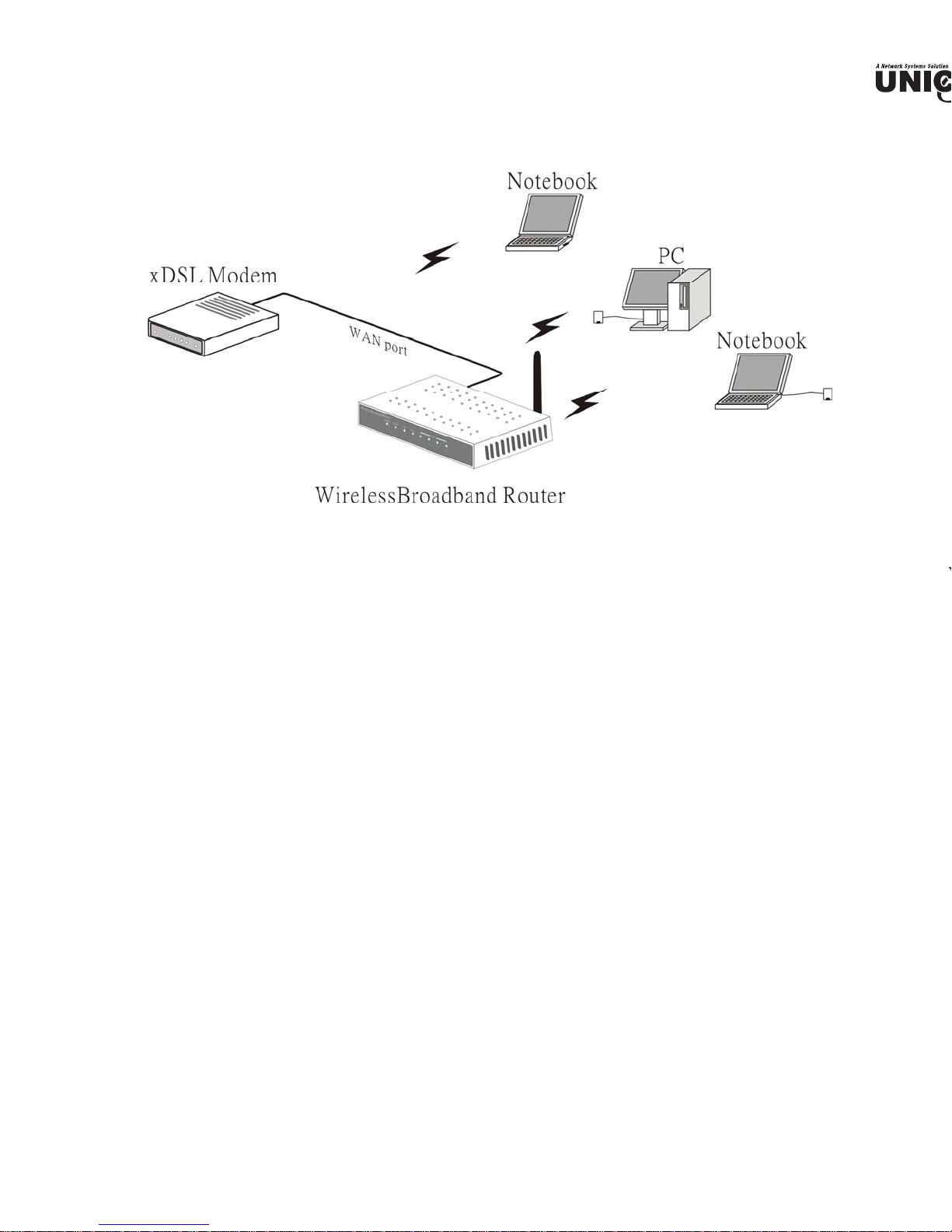
Unicom’s Wireless Broadband Router combines Internet gateway functions with Wireless
LAN) and a Fast Ethernet switch. Designed for the small business and home, it eliminates th
a separate modem and ISP line for each computer while providing a ready connection for all
ed or wireless.
Broadband network access, such as DSL and Cable, is also gaining ground. Since multip
s would be impractical and expensive, there is a need to share one legal IP address over a
rnet connection to link the home with the Internet.
Using a shared Internet connection through Unicom’s Wireless Broadband Router can solv
work access costs. All linked computers can make full use of broadband capabilities over this d
Unicom’s Wireless Broadband Router not only comes equipped with a wide range of featur
also be installed and configured quickly and easily right out of the box. It supports a simple
a Network and Internet access sharing.
The Local Area Network (LAN) connects home computers while allowing any of the com
ccess the Internet, share resources such as printers, or play online games—the basis of the
ily computing lifestyle.
plications:
adband Internet access:
eral computers can share one high-speed broadband connection through wireless or
nections. (WLAN, LAN, and WAN-Internet).
source sharing:
re resources such as printers, scanners, and other peripherals.
e sharing:
hange data, messages, and distribute files among network users.
line gaming:
ily setup online gaming and e-commerce services through the local area network.
ewall:
uilt-in firewall function and anti-hack system for optimum security.
atures:
Page 12

sy configuration via WEB Browser.
Page 13

PACKING AND SETUP
d
s chapter provides unpacking and setup information for Unicom’s Wireless Broadband Router.
packing
Wireless Router box should contain the following items:
(1) Wireless Broadband Router
(1) External power adapter
(1) CD-Rom with this User’s Guide
(1) Installation Quick Guide
(1) Registration Card
ny item is missing or damaged, please contact your local reseller for replacement.
tup
setup of the Wireless Router can be properly performed using the following methods:
The power outlet should be within 1.82 meters (6 feet) of the Broadband Router.
Visually inspect the DC power jack and make sure that it is fully secured to the power adapter.
Make sure that there is proper heat dissipation from and adequate ventilation around the Broa
Router. Do not place heavy objects on the Broadband Router.
Fix the direction of the antennas. Try to place the Wireless Router in a position that can best
your wireless network. Normally, the higher you place the antenna, the better the performanc
be. The antenna’s position enhances the receiving sensitivity.
Page 14
t
b
.
t
b
DWARE INSTALLATION
Panel
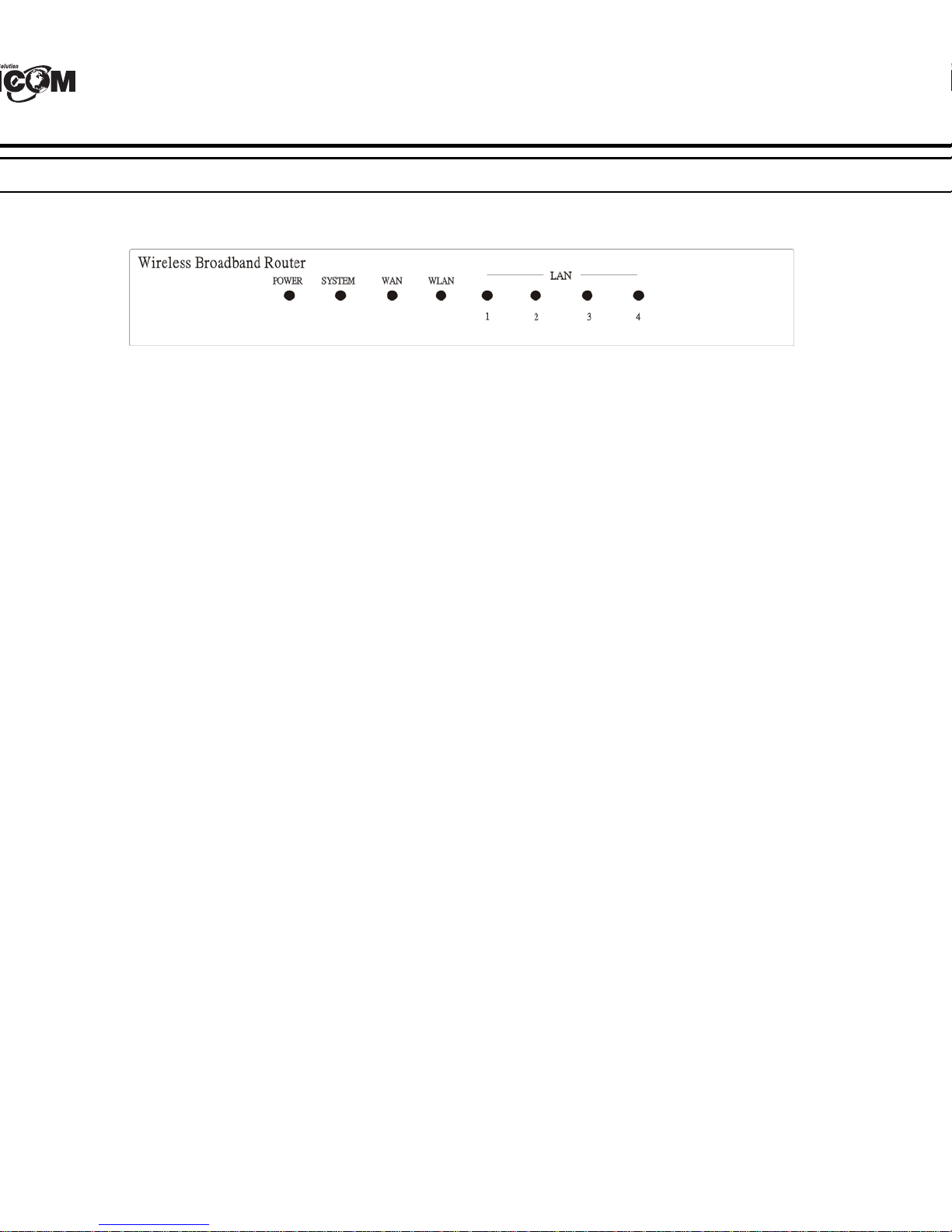
gure below shows the front panel of the Wireless Router.
WEP-72104G-1 Front Panel
ER
ndicator lights green when the hub is receiving power; otherwise, it is off.
EM
indicator blinks green when the Internet Broadband Router is working successfully. If
tor is either solidly on or off, the router is experiencing a failure.
(Link/ACT)
dicators light green when the WAN port is successfully connected to an xDSL/Cable modem.
link green while the WAN port is transmitting or receiving data from the xDSL/Cable modem
N (ACT)
ndicator lights green when there are wireless devices connected and transmitting data to
(Link/ACT)
indicators light green when the LAN ports are connected successfully.
link green while the LAN ports are transmitting data.
Page 15
ar Panel
h
n
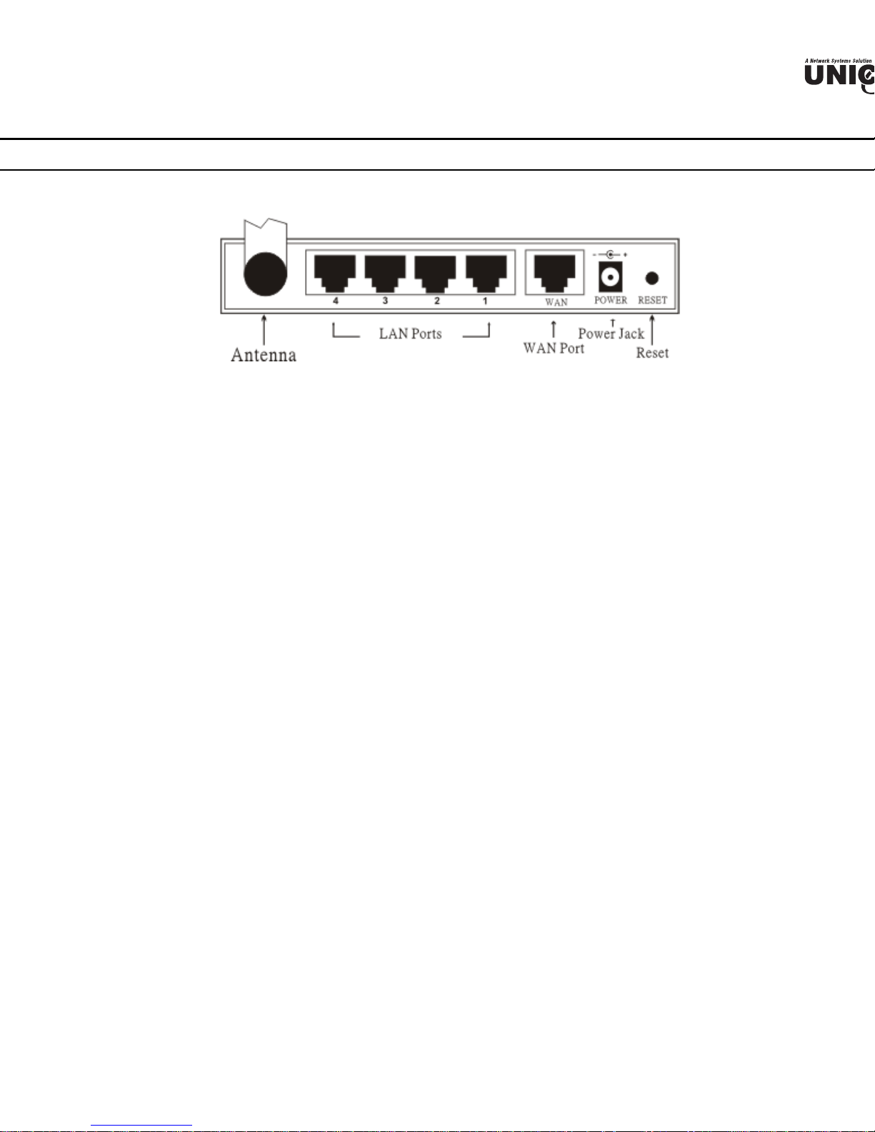
figure below shows the rear panel of the WEP-72104G-1.
WEP-72104G-1 Rear Panel
tenna
re is one 2dB Gain Antenna in the rear panel for wireless connection.
N (1-4)
r RJ-45 10/100Mbps Auto-MDIX ports for connecting to either 10Mbps or 100Mbps Et
nections.
N
nect your xDSL/Cable modem to this port.
IN
g the power adapter into this power jack
SET
this to reset the Router to its factory default settings. It can be a useful way to reset the
sword, however the settings will return to their default mode.
Page 16
E
c
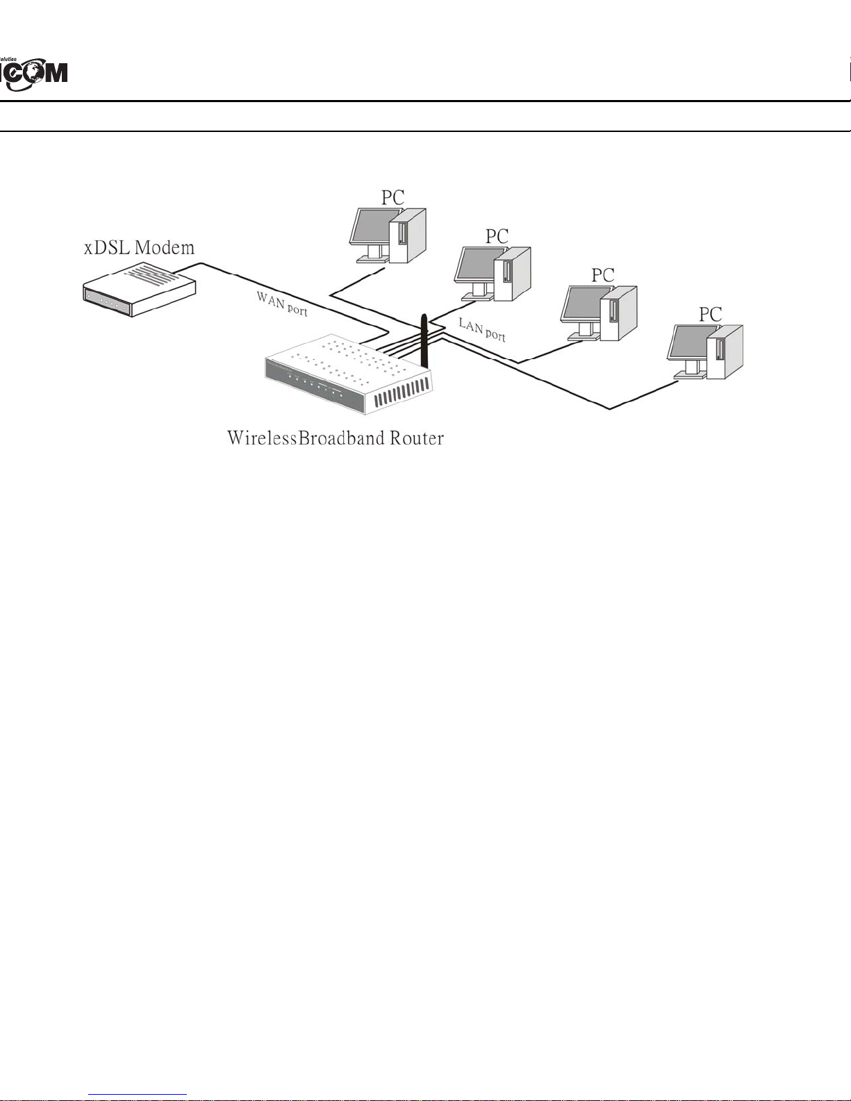
are connections
ect the Router using LAN
g in one end of the network cable to the WAN port of the Wireless Router.
g in the other end of the network cable to the Ethernet port of the xDSL or Cable modem.
ng another network cable, connect the Ethernet port on the computer to a LAN port of the W
04G-1. Since the Wireless Router has four ports, you can connect up to four computers dire
he unit. The Wireless Router functions as both a connection-sharing router and a switch.
Page 17
nnect the Router using Wireless LAN
W
c
h
Plug one end of the RJ45 network cable into the xDSL/Cable Modem.
Plug the other end of the RJ45 network cable into the Wireless Internet Broadband Router's
port.
eck the installation
control LEDs of the WEP-72104G-1 are clearly visible and the status of the network link
n instantly:
ith the power source on, once the device is connected to the broadband modem, the Power,
AN, WLAN and WAN port link LEDs will light up indicating a normal status.
hile the WAN is linked to the ADSL/Cable modem, the WAN port’s Link/ACT LED will lig
hile the LAN is linked to the computer system, the LAN port’s Link/ACT LED will light up.
Page 18

ETWORK TCP/IP SETTING
etwork TCP/IP settings differ based on the computer’s operating system. Configuration
ws 95/98/ME/NT/2000/XP is as follows:
ows 95/98/ME
ck on the “Network neighborhood” icon found on the desktop.
ck the right mouse button and a context menu will be show.
ect “Properties” to enter the TCP/IP setting screen.
ect “Obtain an IP address automatically” on the “IP address” field.
ect “Disable DNS” in the “DNS” field.
Page 19

,
o
ndows 2000
uble click on the “My computer” icon on the desktop. When “My computer” window opens
“Control panel” and then open the “Network dialup connection” applet. Double click
cal area network connection” icon. Select “Properties” to enter the TCP/IP setting window.
n the “Local area network status” window, click on “Properties.”
n the “Local area network connection” window, first select TCP/IP setting and then
Properties.”
Page 20

ows XP
the cursor and click the right button on the “My Network Place” icon.
“properties” to enter the TCP/IP setting window.
t “IP address” to “Obtain an IP address automatically.”
t “DNS” to “Obtain DNS server address automatically.”
Page 21

RELESS ROUTER CONFIGURATION
s
n
h
m
x
r
st, make sure that the network connections are functioning normally.
WEP-72104G-1 can be configured using Internet Explorer 4.0 or newer web browser version
gin to the Wireless Router through WLAN
ore configuring the Wireless Router through WLAN, make sure that the SSID, Channel, a
P are set properly.
default setting of the Wireless Router:
SSID: default
Channel: 6
Security: disable
gin to the Wireless Router through LAN
ore you configure this device, note that when the Wireless Router is configured through an Et
nection, the host computer must be set on an IP subnetwork that can be accessed b
SL/Cable modem. For example, when the default network address of the xDSL/Cable
ernet interface is 192.168.1.x, then the host computer should be set at 192.168.1.xxx (where x
ber between 2 and 254) and the default subnet mask is 255.255.255.0.
ing the Web Browser
Open your Internet browser.
Enter IP address http://192.168.1.1
(the factory-default IP address setting) to the URL web add
location.
When the following dialog box appears, enter the user name and password to login to the main
configuration window, the default username and password is “admin”.
te: To set a password, refer to the "Main Page Password Setting".
Page 22

Page 23

b
p 1: Set up new Password
can change the password and then click “Next” to continue.
p 2: Choose time zone
ect the time zone from the drop down list. Please click “Next” to continue.
p 3: Set LAN connection and DHCP server
user’s IP address and mask. The default IP is 192.168.1.1. To enable DHCP, please click “Ena
CP enable automatically assigns IP addresses. Please assign the range of IP addresses in the fie
nge start” and “Range end”. Please click “Next” to continue.
Page 24

e
u
: Set Internet connection
how the router will set up the Internet connection: Obtain IP automatically, Fixed IP addr
to obtain IP automatically, PPPoE with a fixed IP address, or PPTP.
IP automatically (DHCP client):
has enabled DHCP server, choose "Obtain IP automatically (DHCP client)" to have the ro
IP addresses automatically.
IP Address:
Page 25

he Internet Service Providers assigned a fixed IP address, choose this option and enter the a
d
net mask, gateway IP, and DNS IP addresses for your Broadband Router.
Page 26

o
to obtain IP automatically:
nected to the Internet using a PPPoE (Dial-up xDSL) Modem, the ISP will provide a Passw
ser Name, and then the ISP uses PPPoE. Choose this option and enter the required information.
Page 27

oE with a fixed IP address:
r
onnected to the Internet using a PPPoE (Dial-up xDSL) Modem, the ISP will provide a Passwo
Name and a Fixed IP Address, choose this option and enter the required information.
Page 28

a
h
:
nected to the Internet using an (PPTP) xDSL Modem, enter the IP Address, Subnet M
ay, Server IP, PPTP Account, and PPTP Password in the appropriate fields. If your ISP
ed you with a Connection ID, enter it in the Connection ID field, otherwise, leave it "zero".
Page 29

p 5: Set Wireless LAN connection
x
e
u
t
s
ck “Enable” to enable wireless LAN. If user enables the wireless LAN, type the SSID in the te
select a communications channel. The SSID and channel must be the same as wireless d
mpting communication with the router.
p 6: Restart
Setup wizard is now completed. The new settings will be effective after the Wireless ro
arted. Please click “Restart” to reboot the router. Click “Exit” to exit the wizard without
nges. Click "Back" to modify the previous setting.
Page 30

m
a
k
H
m
nce Setup
LAN Setting
screen enables users to configure the LAN & DHCP Server, set WAN parameters, cre
istrator and User passwords, and set the local time, time zone, and dynamic DNS.
AN & DHCP Server
N and DHCP properties here, such as the host name, IP address, subnet mask, and domain na
and DHCP profiles are listed in the DHCP table at the bottom of the screen.
ame: Type the host name in the text box. The host name is required by some ISPs. The def
ame is "AP-Router."
dress: This is the IP address of the router. The default IP address is 192.168.1.1.
t Mask: Type the subnet mask for the router in the text box. The default subnet mas
5.255.0.
Server: Enables the DHCP server to allow the router to automatically assign IP addresses
s connecting to the LAN. DHCP is enabled by default.
CP client computers are listed in the table at the bottom of the screen, providing the host na
ress, and MAC address of the client.
IP: Type an IP address to serve as the start of the IP range that DHCP will use to assign
Page 31

-
d
h
h
o
nnection Type: Select the connection type, DHCP client, Fixed IP, or PPPoE, from the drop
.
N IP: Select whether user wants to specify an IP address manually, or want DHCP to obtain
ress automatically. When Specify IP is selected, type the IP address, subnet mask, and
eway in the text boxes. User’s ISP will provide with this information.
S 1/2/3: Type up to three DNS numbers in the text boxes. User’s ISP will provide wit
rmation.
C Address: If required by user’s ISP, type the MAC address of the router WAN interface i
d.
S 1/2/3: Type up to three DNS numbers in the text boxes. User’s ISP will provide wit
rmation.
3 Password
s screen enables user to set administrative and user passwords. These passwords are used t
ess to the router interface.
Page 32

o
m
t
istrator: Type the password the Administrator will use to log in to the system. The passw
e typed again for confirmation.
ime
creen enables users to set the time and date for the router's real-time clock, select properly ti
and enable or disable daylight saving.
Time: Displays the local time and date.
one: Select the time zone from the drop-down list.
ht Saving: Enables user to enable or disable daylight saving time. When enabled, select the s
d date for daylight saving time.
Page 33

Wireless
n
d
i
N
s section enables users to set wireless communications parameters for the router's wireless
ture.
1 Basic
s page enables and disables the wireless LAN function, creates a SSID, and selects the chan
eless communications.
ble/Disable: Enables and disables wireless LAN via the router.
D: Type an SSID in the text box. The SSID of any wireless device must match the SSID type
rder for the wireless device to access the LAN and WAN via the router.
annel: Select a transmission channel for wireless communications. The channel of any w
ice must match the channel selected here in order for the wireless device to access the LA
N via the router.
Page 34

e
e
a
-
a
i
uthentication
creen enables user to set authentication type for secure wireless communications. Open Syst
public access to the router via wireless communications. Shared Key requires the user to s
key to exchange data with other wireless clients that have the same WEP key. This router
rts WPA and WPA-PSK.
ntication Type: The authentication type default is set to open system. There are three optio
System: Shared Key, WPA and WPA-PKS.
Enable or Disabled. This is to make WEP enabled or disabled.
Key: Select the level of encryption from the drop-down list. The router supports, 64- and 128
tion.
~ Key 4: Enables user to create an encryption scheme for Wireless LAN transmissions. Manu
set of values for each key. Select a key to use by clicking the radio button next to the key. Cl
r” to erase key values.
Page 35

PA is selected, the below screen is shown. Please set the length of the encryption key a
n
u
ameters for the RADIUS server.
DIUS Server:
nter the IP address of and the Port used by the Primary Radius Server
nter the Shared Secret, which is used by the Radius Server.
nter the IP address of, Port and Shared Secret used by the Secondary Radius Server.
PA-PSK is selected, please set the PSK key in the pass phrase field. The pass phrase sho
ht characters at least.
Page 36

T
d
r
T
c
p
a
n Interval: Type the beacon interval in the text box. User can specify a value from 1 to 1000.
t beacon interval is 100.
hreshold: Type the RTS (Request-To-Send) threshold in the text box. This value stabilizes
If data flow is irregular, choose values between 256 and 2432 until data flow is normalized.
entation Threshold: Type the fragmentation threshold in the text box. If packet transfer e
re high, choose values between 256 and 2432 until packet transfer rates are minimized. (NO
s fragmentation threshold value may diminish system performance.)
Interval: Type a DTIM (Delivery Traffic Indication Message) interval in the text box. User
y a value between 1 and 65535. The default value is 3.
tes (Mbps): Select one of the wireless communications transfer rates, measured in megabytes
, based upon the speed of wireless adapters connected to the WLAN.
Status
election enables user to view the status of the router LAN, WAN connections, and view logs
ics pertaining to connections and packet transfers.
evice Information
creen enables user to view the router LAN, Wireless and WAN configuration
Page 37

N
: This field displays the router's LAN interface MAC address, IP address, subnet mask, and
D
v
r
e
W
d
A
h
p
d
er status. Click “DHCP Table” to view a list of client stations currently connected to the
N interface.
eless: Displays the router's wireless connection information, including the router's wireless int
C address, the connection status, the SSID status, which channel is being used, and whether
bled or not.
N: This field displays the router's WAN interface MAC address, DHCP client status, IP a
net mask, default gateway, and DNS.
ck “DHCP Release” to release all IP addresses assigned to client stations connected to the W
router. Click “DHCP Renew” to reassign IP addresses to client stations connected to the WAN
2 Log
s screen enables user to view a running log of router system statistics, events, and activities. T
lays up to 200 entries. Older entries are overwritten by new entries. The Log screen comman
ollows:
ck “First Page” to view the first page of the log
ck “Last Page” to view the final page of the log
ck “Previous Page” to view the page just before the current page
ck “Next Page” to view the page just after the current page
ck “Clear Log” to delete the contents of the log and begin a new log
ck “Refresh” to renew log statistics
Page 38

e
i
r
og Setting
creen enables user to set router logging parameters.
Server: Type the SMTP server address for the recipient email in the next field.
o: Type an email address for the log to be sent to. Click “Email Log Now” to immediately s
rrent log.
Server: Type the IP address of the Syslog Server if user wants the router to listen and rece
ing Syslog messages.
pe: Enables user to select what items will be included in the log:
ystem Activity: Displays information related to router operation.
ebug Information: Displays information related to errors and system malfunction.
ttacks: Displays information about any malicious activity on the network.
ropped Packets: Displays information about packets that have not been transfer
uccessfully.
otice: Displays important notices by the system administrator.
Page 39
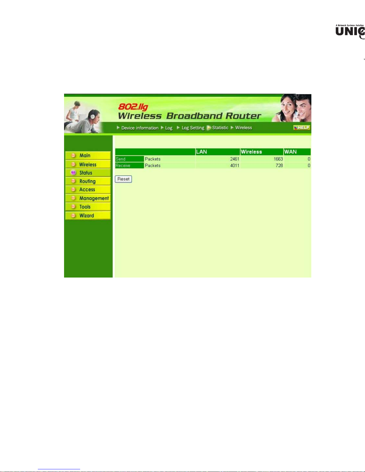
4 Statistic
W
s screen displays a table that shows the rate of packet transmission via the router LAN and
ts (in bytes per second).
ck “Reset” to erase all statistics and begin logging statistics again.
Page 40

e
r
ireless
creen enables user to view information about wireless devices that are connected to the wirel
.
cted Time: Displays how long the wireless device has been connected to the LAN via the route
Address: Displays the devices wireless LAN interface MAC address.
Page 41

Routing
e
t
I
e
r
o
,
s selection enables user to set how the router forwards data: Static and Dynamic. Routing
bles user to view the information created by the router that displays the network interconn
ology.
1 Static
nables user to set parameters by which the router forwards data to its destination if user’s ne
a static IP address.
work Address: Type the static IP address user’s network uses to access the Internet. User’s
work administrator provides user with this information.
work Mask: Type the network (subnet) mask for user’s network. If user does not type a valu
network mask defaults to 255.255.255.255. User’s ISP or network administrator provides use
information.
teway Address: Type the gateway address for network. User’s ISP or network administrator pr
with this information.
rface: Select an interface, WAN or LAN, to connect to the Internet.
tric: Select which metric that user want to apply to this configuration.
: Click to add the configuration to the static IP address table at the bottom of the page.
date: Select one of the entries in the static IP address table at the bottom of the page and
Page 42

t
Click the radio buttons to enable or disable NAT.
mit: Click the radio buttons to set the desired transmit parameters, disabled, RIP 1, or RIP 2.
e: Click the radio buttons to set the desired transmit parameters, disabled, RIP 1, or RIP 2.
outing Table
creen enables user to view the routing table for the router. The routing table is a database crea
router that displays the network interconnection topology.
Page 43

Access
e
e
l
n
d
e
s page enables user to define access restrictions, set up protocol and IP filters, create virtual s
ine access for special applications such as games, and set firewall rules.
1 MAC Filters
bles user to allow or deny Internet access to users within the LAN based upon the MAC addr
ir network interface. Click the radio button next to “Disabled” to disable the MAC filter.
able: Once the function of MAC filter is disabled, those listed in the MAC Table are al
rnet access.
ble: All users are allowed Internet access except those users in the MAC Table are denied I
ess.
C Table: Use this section to create a user profile which Internet access is denied or allowe
r profiles are listed in the table at the bottom of the page. (Note: Click anywhere in the item.
line is selected, the fields automatically load the item's parameters, which user can edit.)
me: Type the name of the user to be permitted/denied access.
C Address: Type the MAC address of the user's network interface.
: Click to add the user to the list at the bottom of the page.
date: Click to update information for the user, if user has changed any of the fields.
lete: Select a user from the table at the bottom of the list and click “Delete” to remove th
Page 44

t
P Filter
creen enables user to define a minimum and maximum IP address range filter; no IP addres
within the range are allowed Internet access. The IP filter profiles are listed in the table at
of the page. (Note: Click anywhere in the item. Once the line is selected, the fie
atically load the item's parameters, which user can edit.)
Page 45

: Click “New” to erase all fields and enter new information.
i
r
e
v
v
e
N
d
4 Virtual Server
s screen enables user to create a virtual server via the router. If the router is set as a virtual s
ote users requesting Web or FTP services through the WAN are directed to local servers
N. The router redirects the request via the protocol and port numbers to the correct LAN serve
tual Sever profiles are listed in the table at the bottom of the page.
te: When selecting items in the table at the bottom, click anywhere in the item. The line is sel
the fields automatically load the item's parameters, which user can edit.
ble: Click to enable or disable the virtual server.
me: Type a descriptive name for the virtual server.
tocol: Select a protocol (TCP or UDP) to use for the virtual server.
vate Port: Type the port number of the computer on the LAN that is being used to act as a
er.
lic Port: Type the port number on the WAN that will be used to provide access to the virtual s
Server: Type the LAN IP address that will be assigned to the virtual server.
: Click to add the virtual server to the table at the bottom of the screen.
date: Click to update information for the virtual server if user have selected a list item an
Page 46

n
o
s
i
a
e: Click to enable or disable the application profile. When enabled, users will be able to con
application via the router WAN connection. Click “Disabled” on a profile to prevent users fr
ing the application on the WAN.
: Type a descriptive name for the application.
r: Defines the outgoing communication that determines whether the user has legitimate acces
plication.
rotocol: Select the protocol (TCP, UDP, or ICMP) that can be used to access the application.
ort Range: Type the port range that can be used to access the application in the text boxes.
ncoming: Defines which incoming communications users are permitted to receive.
rotocol: Selects the protocol (TCP, UDP, or ICMP) that can be used by the incom
ommunication.
ort: Type the port number that can be used for the incoming communication.
lick to add the special application profile to the table at the bottom of the screen.
e: Click to update information for the special application if user have selected a list item and h
changes.
: Select a list item and click Delete to remove the item from the list.
Click “New” to erase all fields and enter new information.
MZ
Page 47

t
ble: Click to enable or disable the DMZ.
Z Host IP: Type a host IP address for the DMZ. The computer with this IP address acts as a
t with unlimited Internet access.
ly: Click to save the settings.
7 Firewall Rule
s screen enables user to set up the firewall. The router provides basic firewall functions, by fil
the packets that enter the router using a set of rules. The rules are in an order sequence list--the
rule number, the higher the priority the rule has.
Page 48

a
t
a
e: Defines the source of the incoming packet where rule is applied.
nterface: Select which interface (WAN or LAN) the rule is applied to.
P Range Start: Type the start IP address where rule is applied.
P Range End: Type the end IP address where rule is applied.
ation: Defines the destination of the incoming packet where rule is applied.
nterface: Select which interface (WAN or LAN) the rule is applied to.
P Range Start: Type the start IP address where rule is applied.
P Range End: Type the end IP address where rule is applied.
rotocol: Select the protocol (TCP, UDP, or ICMP) of the destination.
ort Range: Select the port range.
Click to add the rule profile to the table at the bottom of the screen.
te: Click to update information for the rule if user have selected a list item and have m
es.
: Select a list item and click “Delete” to remove the item from the list.
Click “New” to erase all fields and enter new information.
ty Up: Select a rule from the list and click “Priority Up” to increase the priority of the rule.
ty Down: Select a rule from the list and click “Priority Down” to decrease the priority of
te Priority: After increasing or decreasing the priority of a rule, click “Update Priority” to s
anges.
Page 49

Management
c
m
t
o
n
U
a
nagement enables user to set up Remote Management features.
1 Remote Management
s screen enables user to set up remote management. Using remote management, the router
figured via a Web browser. A user name and password are required to perform remote manage
TP: Enables user to set up HTTP access for remote management.
ow to Ping WAN Port: Type a range of router IP addresses that can be pinged from remote loca
NP: UPNP is short for Universal Plug and Play that is a networking architecture that pr
patibility among networking equipment, software, and peripherals. The Router is an UPnP e
ter and will only work with other UPnP devices/software. If user does not want to use the
ctionality, selecting “Disabled” can disable it.
MING MODE: If user is experiencing difficulties when playing online games or even c
lications that use voice data, user may need to enable Gaming Mode for these applications to
rectly. When not playing games or using these voice applications, it is recommended that G
de be disabled.
TP: Enables user to set up PPTP access for remote management.
ec: Enables user to set up IPSec access for remote management.
NT: Default is stealth. This enables user to set port 113 stealth.
Page 50

Page 51

2 Settings
.
r
s
s screen enables user to save settings as a profile and load profiles for different circumstances
also load the factory default settings, and run a setup wizard to configure the router and
rface.
e Settings: Click “Save” to save the current configuration as a profile that can load when neces
d Settings: Click “Browse” and go to the location of a stored profile. Click “Load” to load the
file's settings.
tore Factory Default Settings: Click “Restore” to restore the default settings. All configuration
nges will be lost.
Page 52

a
irmware
creen enables user to keep the router firmware up to date.
follow the below instructions:
load the latest firmware from the manufacturer's Web site, and save it to disk.
“Browse” and go to the location of the downlo
ded firmware file.
the file and click “Upgrade” to update the firmware to the latest release.
Page 53
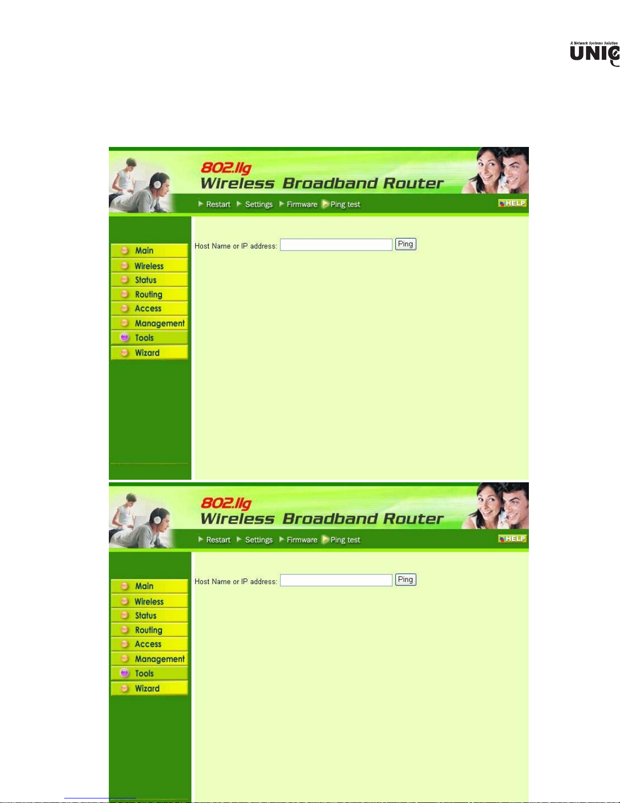
4 Ping Test
ping test enables user to determine whether an IP address or host is present on the Internet.
host name or IP address in the text box and click Ping.
Page 54

Technical Specifications
Standards IEEE 802.3u 100BASE-TX Fast Ethernet
IEEE 802.11g; IEEE 802.11b
Protocol CSMA/CD
Radio Technology IEEE 802.11g Orthogonal Frequency Division Modulation
Data Transfer Rate 802.11b: 1, 2, 5.5, 11Mbps (auto sense)
802.11g: 6, 9, 12, 18, 24, 36, 48, 54Mbps @802.11g(auto sense)
Ethernet: 10Mbps (half duplex), 20Mbps (full-duplex)
Fast Ethernet: 100Mbps (half duplex), 200Mbps (full- duplex)
Topology Star
Receiver Sensitivity 54Mbps: Typical -70dBm @ 10% PER (Packet Error Rate)
11Mbps: Typical -85dBm @ 8% PER (Packet Error Rate)
TX Power 13dBm typically @ 802.11g
13dBm typically @ 802.11b
Network Cables 10Base-T: 2-pair UTP Cat. 3,4,5 (100 m), EIA/TIA- 568 100-ohm
STP (100 m)
100Base-TX: 2-pair UTP Cat. 5 (100 m), EIA/TIA-568 100-ohm
STP (100 m)
Frequency Range 2412 ~ 2484 MHz ISM band (channels 1 ~ 14)
Modulation Schemes DBPSK/DQPSK/CCK/OFDM
Security 64/128-bits WEP Encryption; WPA, WPA-PSK
Channels 1 ~ 11 channels (FCC); 1 ~ 13 channels (ETSI);
1 ~ 14 channels (MKK)
Number of Ports LAN: 4 x 10/100Mbps Auto-MDIX Fast Ethernet port
WAN: 1 x 10/100Mbps Auto-MDIX Fast Ethernet port
Physical and Environmental
DC inputs DC 5V 2.5A
Power Consumption 3W (Max)
Temperature
Humidity Operating: 10% ~ 90%, Storage: 5% ~ 90%
Dimensions 147 x 115 x 35 mm (W x H x D) without Antenna
EMI: FCC Class B, CE Mark B
Operating: 0° ~ 40° C, Storage: -10° ~ 70° C
 Loading...