

Page 1
Installation guide
Rev. 032304
( Continued )
Specifications
• 2-Channel (Stereo) control
• Impedance matching:
2x, 4x, 8x and 16x multiplying
• 12 step rotary knob:
up to 42dB total attenuation
• Frequency: 20 - 20,000 Hz
• Power handling: 100 watts maximum
Unicom’s Wall Mount Impedance Matching Volume
Control is crafted for maximum performance and
durability. Impedance matching ensures crystal clear
sound in any room in your home. Follow the simple
instructions below to start enjoying your quality Unicom
product.
Installation Instructions
1) Remove about 1/4” of insulation from the ends of all
wires to be connected to the Volume Control. Twist the
cable strands to tighten.
Note: The removable speaker/input connectors accept
up to 14 gauge cable.
2) For easier installation, remove the blue connectors
from the Volume Control.
3) Loosen the set screws on the connectors.
4) Connect the leads from the amplifier or receiver to the
INPUT connections; LEFT L (+) and (-) and RIGHT R (+)
and (-). Insert the wire into the correct opening and
tighten the screws firmly.
5) Connect the speaker wires from the speakers to the
OUTPUT connector on the Volume Control. Make sure
that the positive (+) and negative (-) wires of each
speaker are mated to the correct opening on the
connector. Incorrectly wiring this connection will
result in poor sound quality.
6) Replace the blue connectors.
7) Configure jumpers for the total number of speaker
pairs used in the entire installation.
(see note on page 2)
8) Install the completed assembly into the electrical box
or opening.
Note: Insert carefully to avoid excessive strain on the
set screws. If necessary, pre-dress the wires for easier
mounting.
That’s it! Now you’ve made all of the necessary
connections.
Overview: This guide will facilitate the installation of the Wall Mount Impedance Matching
Volume Control (p/n: UHB1-VC242). Also discussed are cable handling guidelines.
Product: Wall Mount Impedance Matching Volume Control (p/n: UHB1-VC242)
Tools
you’ll need:
small flat or phillips screwdriver, wire cutters/strippers
UNICOM Electric, Inc.
908 Canada Court
City of Industry, California 91748
U.S.A.
www.unicomlink.com
E-mail: info@unicomlink.com
Technical Support: 1.800.346.6668
International: 626-964-7873
UNICOM’s 5 Year Product Warranty will warrant that all UNICOM
products*will be free from defects in material and workmanship
for a period of 5 years from the original date of purchase.
*
Excludes all UNICOM testers and Industrial Switches.
See www.unicomlink.com for more information
Page 2
©UNICOM 2004. UNICOM is a trademark of UNICOM Electric, Inc.
All Rights Reserved.
UNICOM Electric, Inc.
908 Canada Court
City of Industry, California 91748
U.S.A.
www.unicomlink.com
E-mail: info@unicomlink.com
Technical Support: 1.800.346.6668
International: 626-964-7873
Impedance Jumper settings
for 4 Ω amplifier*
Speaker Ohms (Ω) 2X 4X 8X 16X
8 Ω 4 pair 8 pair 16 pair 32 pair
4 Ω 2 pair 4 pair 8 pair 16 pair
*Assumes Volume set at Maximum
Impedance Jumper settings
for 8 Ω amplifier*
Speaker Ohms (Ω) 2X 4X 8X 16X
8 Ω 2 pair 4 pair 8 pair 16 pair
4 Ω 1 pair 2 pair 4 pair 8 pair
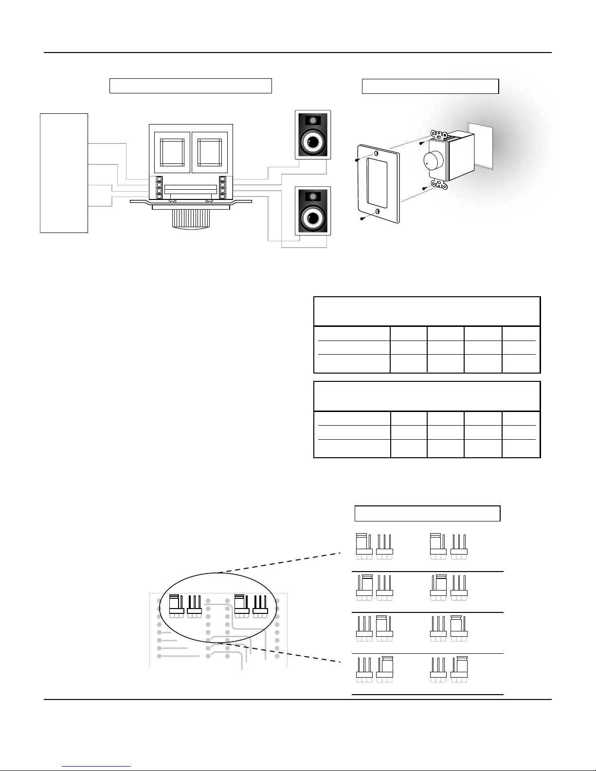
AUDIO
Configuration of Jumpers
The maximum power transfer from an amplifier to a
speaker occurs when the impedance of the speaker
matches that of the amp. This is where the Impedence
matching function of the Unicom Full House Volume
Control becomes important. This function reduces the risk
of damage to the amplifier and improves sound quality.
To set the jumpers, follow the steps below.
1) Determine the ohm rating of the speakers and
amplifier and the TOTAL number of speaker pairs
used in the entire installation.
2) Using these numbers, locate the appropriate setting
on the accompanying charts. (fig.1)
3) Set the jumper to the proper setting. (fig.2)
(i.e., 8Ω Amplifier + 8Ω Speakers + 4 pairs = 4X)
Note: If an odd number of speaker pairs is used,
round up to next higher jumper setting.
(i.e., if 7 pairs of speakers are used, set jumpers to 8X)
fig. 1
fig. 2
SOURCE
R+
R-
L-
L+
CONNECTION DIAGRAM
INPUT OUTPUT
R+ R- L- L+
INPUT
L- L+ R+ R-
OUTPUT
ASSEMBLY DIAGRAM
RIGHT SPEAKER
LEFT SPEAKER
JUMPER SETTINGS
X16
X8
X16
X2
X4
X8
X16
X2
X4
X2
X4
X8
X16
X16
X2
X4
X8
X16
X2
X4
X8
X16
X2
X4
X8
X16
X8
X16
X8
X16
X8
X16
X2
X4
X8
X8
X2
X4
X4
X2
X4
X2
X2
X4
 Loading...