

Page 1
PoE Splitter
Power over Ethernet Splitter
802.3af
PN: POE-22001T
U
SER’S MANUAL
Page 2

Content
Overview ...........................................................1
Features ............................................................1
Hardware Description ......................................2
Package Contents ............................................2
Installation ........................................................5
Technical Specification ...................................6
Page 3
Overview
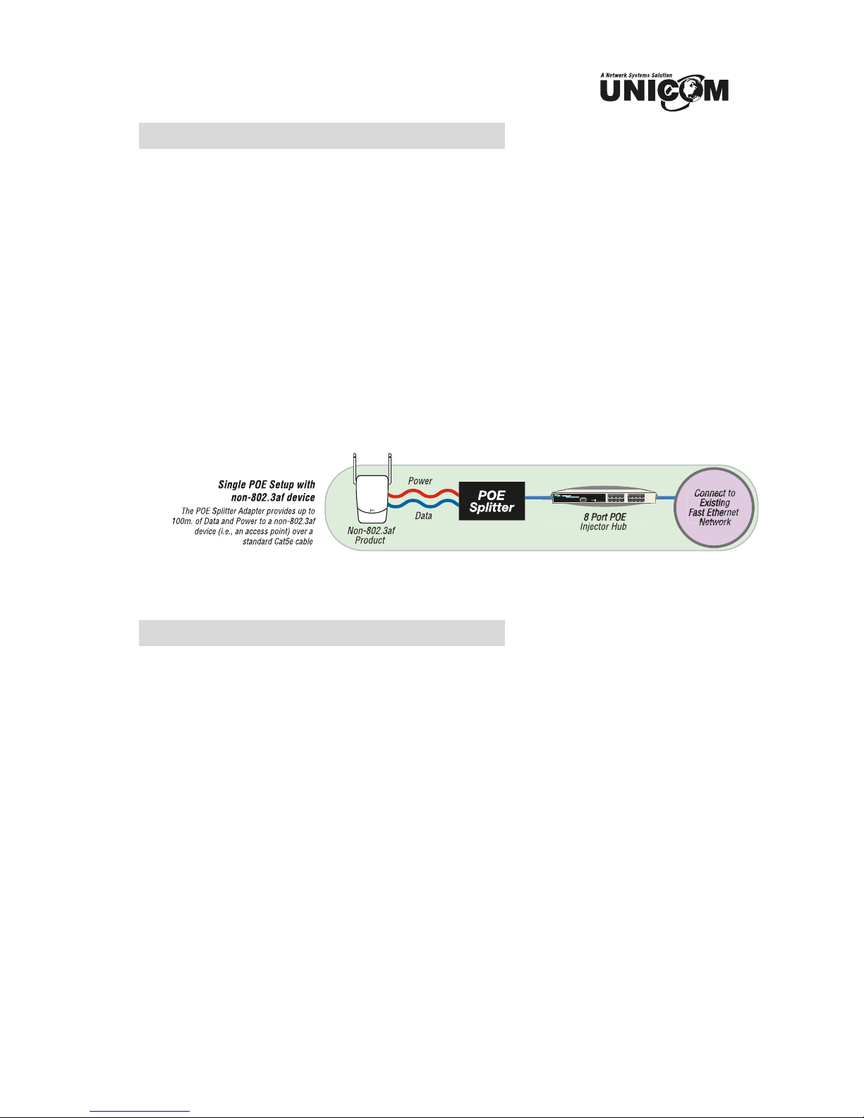
Unicom's new Power over Ethernet (PoE) Splitter Adapter provides
Ethernet data and DC power to a network device that is not compliant with
the IEEE802.3af standard (non-PoE). This adapter effectively provides
Ethernet data and DC power to a non-PoE device with a single cable and
allows it to operate within a PoE network. PoE is an efficient and
convenient solution for remote applications where available space is
limited and/or no power source is readily available. Following is a sample
PoE Splitter application.
Features
Adjustable Output Range: 5v, 7.5v, 9v, and 12v
IEEE802.3af compliant
Short circuit protection
Delivers DC power and data to no-PoE devices
Plug-and-Play
Light weight and compact
Perfect for Wireless AP, Bluetooth AP, IP Cameras, IP Telephones,
and remote power-feeding applications
Two different-sized detachable power cables for added flexibility
Page 4

Package Contents
(1) Power over Ethernet Splitter
(2) DC Power Cables – 5.5x2.0mm and 5.5x2.5mm
User's Manual
PoE Splitter DC Power Cables User's Manual
With adjustable output
Figure 1-1. Package Contents
Compare the contents of your Power over Ethernet Splitter package with
the standard checklist above. If any item is missing or damaged, please
contact your local dealer for service.
Page 5

Hardware Description
Unicom's Power over Ethernet Splitter Adapter has three connection ports,
one LED indicator, and a voltage adjustment DIPswitch.
Data In port: This is an RJ-45 Ethernet interface port for data
transmission into the PoE Splitter. This port connects with a PoE
injector.
The Data In port
Data Out port: This is an RJ-45 Ethernet port and has a detachable
RJ-45 cable for connecting with a PoE device such as a camera.
Power Out port: The adapter supports and includes two types of
power cables – 5.5 x2.0mm and 5.5x2.5mm. The Power Out port
transmits DC power to a 5V, 7.5V, 9V or 12V device.
Data Out and Power Out ports
LED indicator: The splitter features one system Power LED indicator.
It is located on the top of the Power over Ethernet Splitter.
Page 6

System Power LED indicator
DIPswitch: The DIPswitch changes the splitter voltage allowing for it
to operate with a variety of products. It provides four voltage values –
5V, 7.5V, 9V and 12V. The default is 5V. Before adjusting the
DIPswitch, disconnect the power from Splitter Adapter.
DIPswitch
Page 7

Installation
To install the Power over Ethernet Splitter, please follow the steps below.
1. Use an RJ-45 cable to connect the Data In port on the Power over
Ethernet Splitter Adapter with the Data Out port of a PoE Hub. If the
hub does not support PoE function, you'll need to install a PoE Injector
(pn: POE-32001T) between the hub and splitter.
2. Use an RJ-45 cable to connect the Data Out port on the PoE Splitter
Adapter to a remote device (Such as a router, access point, camera,
etc.).
3. Choose the proper power cable (either 2.0mm or 2.5mm) and plug the
straight end into the Power Out port on the Splitter.
4. Plug the right-angle end of the power cable into the device’s power
port.
5. Adjust the Voltage on the Splitter to match the remote device. It
supports four voltage values – 5V, 7.5V, 9V and 12V. The default
value is 5V. Before adjusting the DIPswitch, please disconnect the
power from the Splitter Adapter.
6. Before powering on the system, ensure all connections and the voltage
is set correctly.
The PoE Splitter connects to the Switch or POE Injector in the
Data In port.
The PoE Splitter connects to the remote device through two
connection ports – Data Out and Power Out.
The voltage is set correctly: 5V, 7.5V, 9V and 12V.
Page 8

Technical Specification
IEEE802.3 10BASE-T
Standard
IEEE802.3u 100BASE-TX
IEEE802.3af Power over Ethernet
Power jack
diameter
(2) Power Cables,
each with straight and a right angle plugs
Plug dimension: 5.5 x 2.0mm, 5.5 x 2.5mm
DIPswitch Four-segment output voltage switch
Data / Power In: 1 x RJ-45.Data pin 1,2,3,6
Power pin:
4,5(V+), 7,8(V-) and 1,2(V+), 3,6(V-)
Connector
Data Out: 1 x RJ-45, Data pin 1,2,3,6
Power out jack: 5V, 7.5V, 9V, 12V (Adjustable)
Maximum feeding current: 2.0A@5V
10Base-T: 2-pair UTP/STP,
Cat.3, 4,5 cable, EIA/TIA-568 100-ohm (100m)
Network Cable
100Base-TX: 2-pair UTP/STP,
Cat.5e cable, EIA/TIA-568 100-ohm (100m)
LED System: power (green)
Power Input DC 48V
Operating
environment
Dimension 80mm x 55mm x 26mm (L x W x H)
EMI & Safety FCC Class B, CE, CE/EN60950
0˚~ 40˚, 90% Humidity (non-condensing)
Page 9

Phone: 626.964.7873 or 800.346.6668 Fax: 626.964.7880
www.unicomlink.com e-mail: info@unicomlink.com
UNIDOC020905
908 Canada Court
City of Industry, CA 91748 U.S.A.
 Loading...