

Page 1
908 Canada Court
City of Industry, CA 91748 U.S.A.
Phone: 626.964.7873 or 800.346.6668 Fax: 626.964.7880
www.unicomlink.com e-mail: info@unicomlink.com
©UNICOM 2004. UNICOM and “A Network Systems Solution” are trademarks of UNICOM Electric, Inc.
All rights reserved. Specifications subject to change without notice.
Rev: 09.04
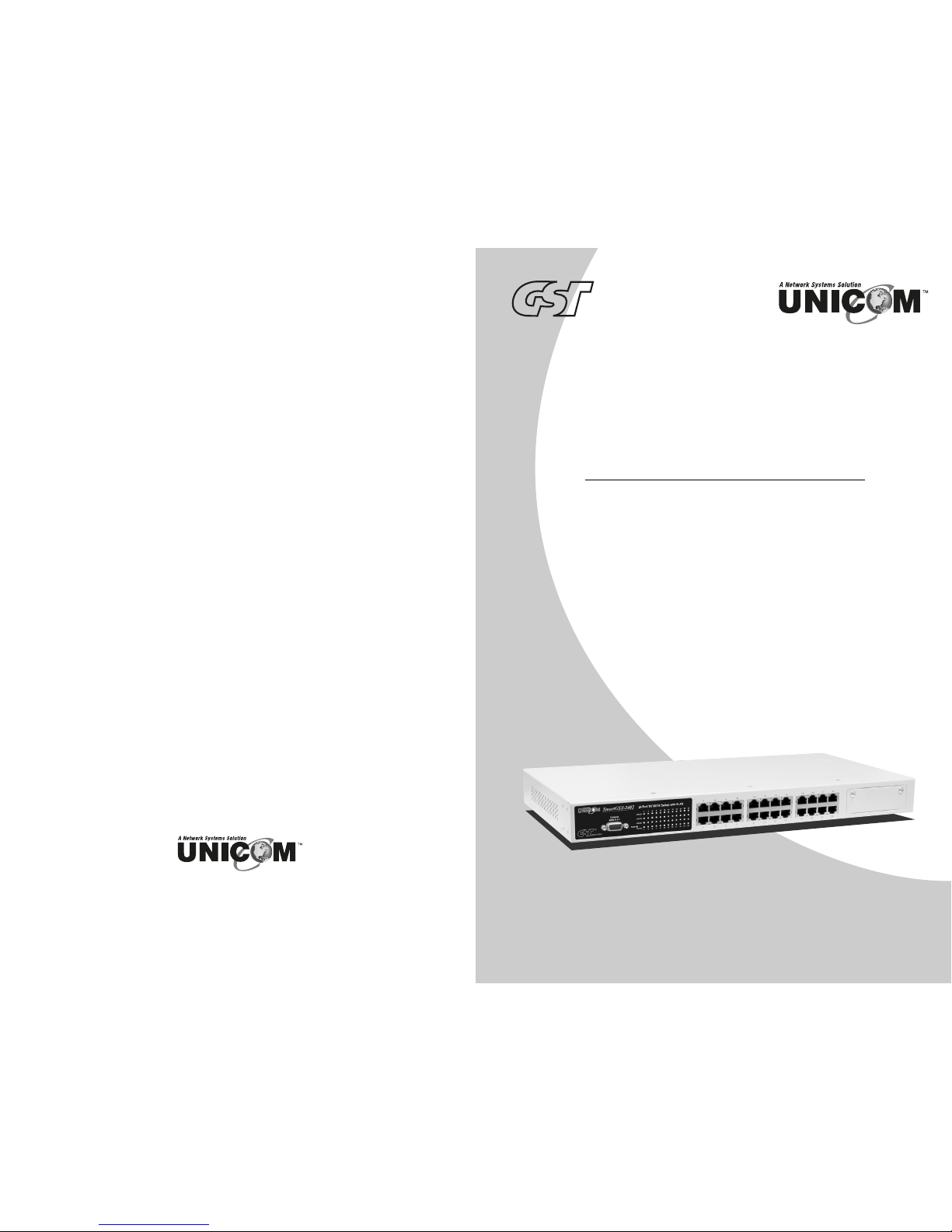
24 Port 10/100Base-TX Switch
with Dual Port 100/1000 Module Slot
SmartGST-2402
USER’S MANUAL
GEP-31124T-1
series
™
Page 2

1. INTRODUCTION ......................................................................................................1
Features....................................................................................................................2
Software Features.....................................................................................................3
Package Contents.....................................................................................................4
Ethernet Switching Technology.................................................................................4
2. HARDWARE DESCRIPTION...................................................................................6
Front Panel ...............................................................................................................6
LED Indicators ..........................................................................................................7
Rear Panel ................................................................................................................7
Desktop Installation...................................................................................................8
Rack-mounted Installation.........................................................................................9
3. NETWORK APPLICATION....................................................................................11
4. CONSOLE MANAGEMENT...................................................................................14
Login in the Console Interface ................................................................................14
Main Menu ..............................................................................................................15
Port Status ..............................................................................................................17
Port Configuration ...................................................................................................17
Trunk Configuration.................................................................................................18
Trunk Status............................................................................................................19
QoS.........................................................................................................................20
Priority Tag Insert/Remove .....................................................................................21
System ....................................................................................................................21
VLAN Member Setup ..............................................................................................22
Add VLAN Group.................................................................................................22
Delete VLAN Group.............................................................................................23
Save........................................................................................................................24
5. TROUBLESHOOTING ...........................................................................................25
6. TECHNICAL SPECIFICATION ..............................................................................27
Page 3

APPENDIX .................................................................................................................29
Console Port Pin Assignments................................................................................29
Cables.....................................................................................................................30
100BASE-TX/10BASE-T Pin Assignments .............................................................30
Page 4
1. Introduction
gh p
Welcome to the World of Network Switching. In modern business,
communication and information sharing are fundamental to success.
Computer networks have proven to be one of the fastest ways of
communication.
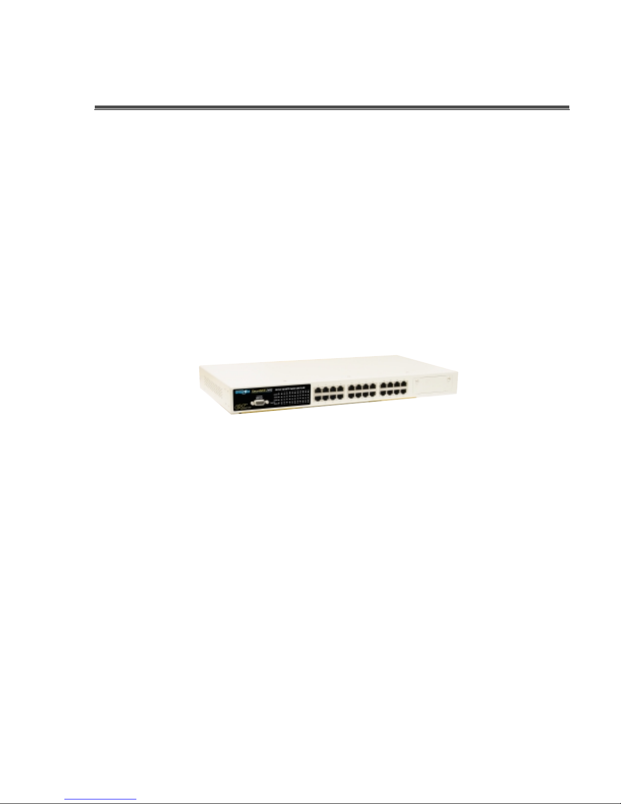
The SmartGST-2402 is a multi-port Switch that can be used to build high-
performance switched workgroup networks. It is a store-and-forward device
that offers low latency for high-speed networking and is targeted at
workgroup, department, or backbone computing environments.
Figure 1-1. SmartGST-2402
The SmartGST-2402's “store-and-forward“ switching scheme allows the
switch to auto-learn and store source address in an 8K-entry MAC address
table.
MDI (Medium Dependent Interface) Port is also called an "uplink port". The
MDI port does not cross the transmission and reception lines, which is done
by the regular ports (MDI-X ports) that connect to end stations. In general,
MDI means connecting to another Hub or Switch while MDIX means
connecting to a workstation or PC. Therefore, Auto MDI/MDIX means that
you can connect to another Switch or workstation without changing non-
crossover or crossover cabling.
The SmartGST-2402 has twenty four auto-sensing 10/100Base-TX RJ-45
ports plus one module slot for optional dual port 100Base-FX, 1000T, and
1000SX/LX Mini GBIC modules. This enables hi
erformance expansion
Page 5

connections over long distances.
Features
IEEE802.3 10Base-T, IEEE802.3u 100Base-TX/FX, IEEE802.3ab
1000Base-T, IEEE802.3z Gigabit fiber
Twenty-four 10/100TX ports plus one expansion slot with RS-232 for
management
Expansion modules available: 100FX, 1000T, 1000SX/LX
IEEE802.3x Flow control:
Pause-frame for full duplex mode
Backpressure for half duplex mode
Store-and-forwarding switching architecture for abnormal packet filtering
High switch fabric up to 8.8Gbps
8K-entry MAC address table
2.5Mbits memory buffer
Broadcast Storm filter supported
Support PortBase VLAN
Class of service supported
IEEE802.3ad Port trunk supported
Non-Blocking full wire speed architecture
Fan free design
Ingress and egress bandwidth control
Page 6
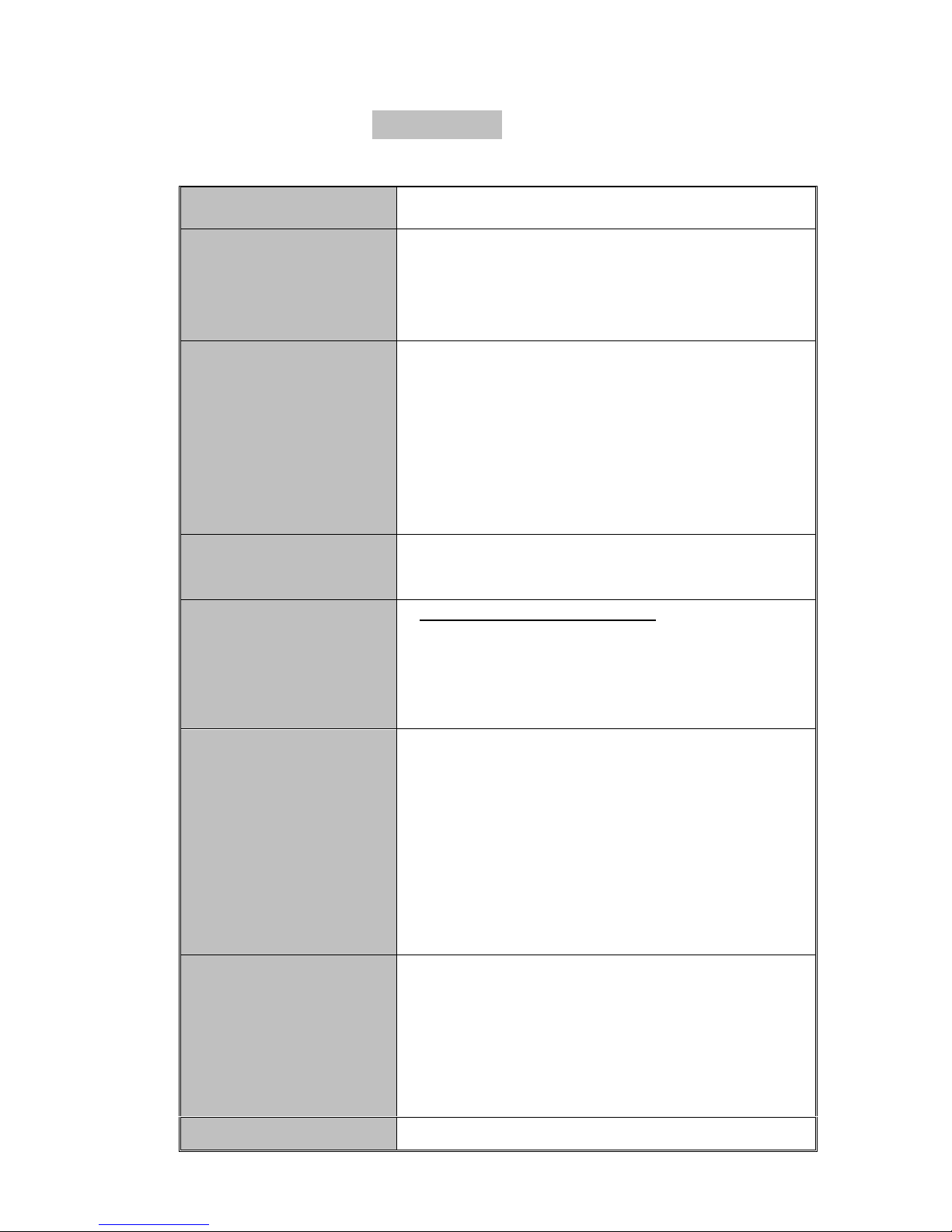
Software Features
Management In-Band Local Console (RS-232)
Link speed, link mode, Port disable/Enable, Port
Port configuration
Port Trunk
VLAN
QoS
Flow control disable/Enable, Port Auto
negotiation
IEEE802.3ad port trunk. Trunk groups up to 8.
Maximum trunk port members up to 4.
Trunk 1 (#1,#2), Trunk 2 (#3,#4), Trunk 3
(#5~#8), Trunk 4 (#9~#12), Trunk 5 (#13~#16),
Trunk 6 (#17~#20), Trunk 7 (#21~#24), Trunk 8
(Exp. module port #25, #26)
Port Based VLAN
VLAN entry up to 26
3 Types of quality of service:
1. Port based priority.
2. TCP/IP TOS/DiffServ (DS) priority field.
3. 802.1p priority tag
System provides two queues for High and Low
priority.
Support priority weighted ration (H /L): 1:0
Class of Service
(always high priority), 4:1 (4 High priority, 1 Low
priority packet), 8:1 (8 High priority, 1 Low
priority packet), 16:1 (16 High priority, 1 Low
priority packet)
Each port’s bandwidth is independently
configurable on both ingress and egress traffic.
Bandwidth Control
Each port's bandwidth can be configured as:
128kbps, 256Kbps, 512Kbps, 1Mbps. 2Mbps,
4Mbps, or 8Mbps Independently
Broadcast Storm Disable or Enable.
Page 7
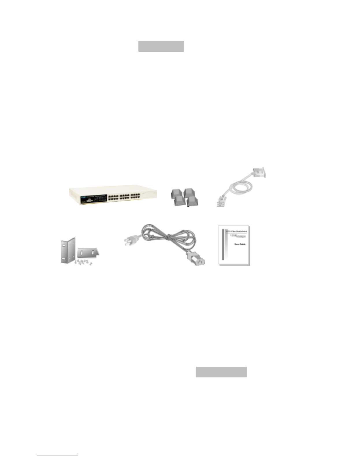
Package Contents
Unpack the contents of the SmartGST-2402 and verify them against the
checklist below.
SmartGST-2402 Fast Ethernet Switch
Power Cord
Four Rubber Feet
RS-232 cable
User Guide
Rack mount kit
SmartGST-2402 Four Rubber Feet RS-232 Cable
Rack-mounted Kit Power Cord User Guide
Figure 1-2. Package Contents
Compare the contents of your SmartGST-2402 package with the standard
checklist above. If any item is missing or damaged, please contact your local
dealer for service.
Ethernet Switching Technology
Ethernet Switching Technology dramatically boosted the total bandwidth of a
network, eliminated congestion problems inherent with CSMA/CD (Carrier
Sense multiple access with Collision Detection) protocol, and greatly reduced
unnecessary transmissions.
Page 8

This revolutionized networking. First, by allowing two-way, simultaneous
transmissions over the same port (Full-duplex), which essentially doubled the
bandwidth. Second, by reducing the collision domain to a single switch-port,
which eliminated the need for carrier sensing. Third, by using the store-and-
forward technology’s approach of inspecting each packet to intercept corrupt
or redundant data. By employing address learning, this switching eliminated
unnecessary transmission that slowed the network.
Auto-negotiation regulates the speed and duplex of each port, based on the
capability of both devices. Flow-control allows transmission from a 100Mbps
node to a 10Mbps node without loss of data. Auto-negotiation and flow-control
may need to be disabled for some networking operations involving legacy
equipment. Disabling the auto-negotiation is accomplished by fixing the speed
or duplex of a port.
Ethernet Switching Technology supplies higher performance at lower costs
than other solutions. Wider bandwidth, no congestion, and the reduction in
traffic is why switching is replacing expensive routers and inefficient hubs as
the ultimate networking solution. Switching brings a whole new way of thinking
to networking.
Page 9
2. Hardware Description
This Section describes the hardware of the SmartGST-2402 and gives a
physical and functional overview of this switch.
The physical dimensions: 440mm x 161mm x 44mm (L x W x H)
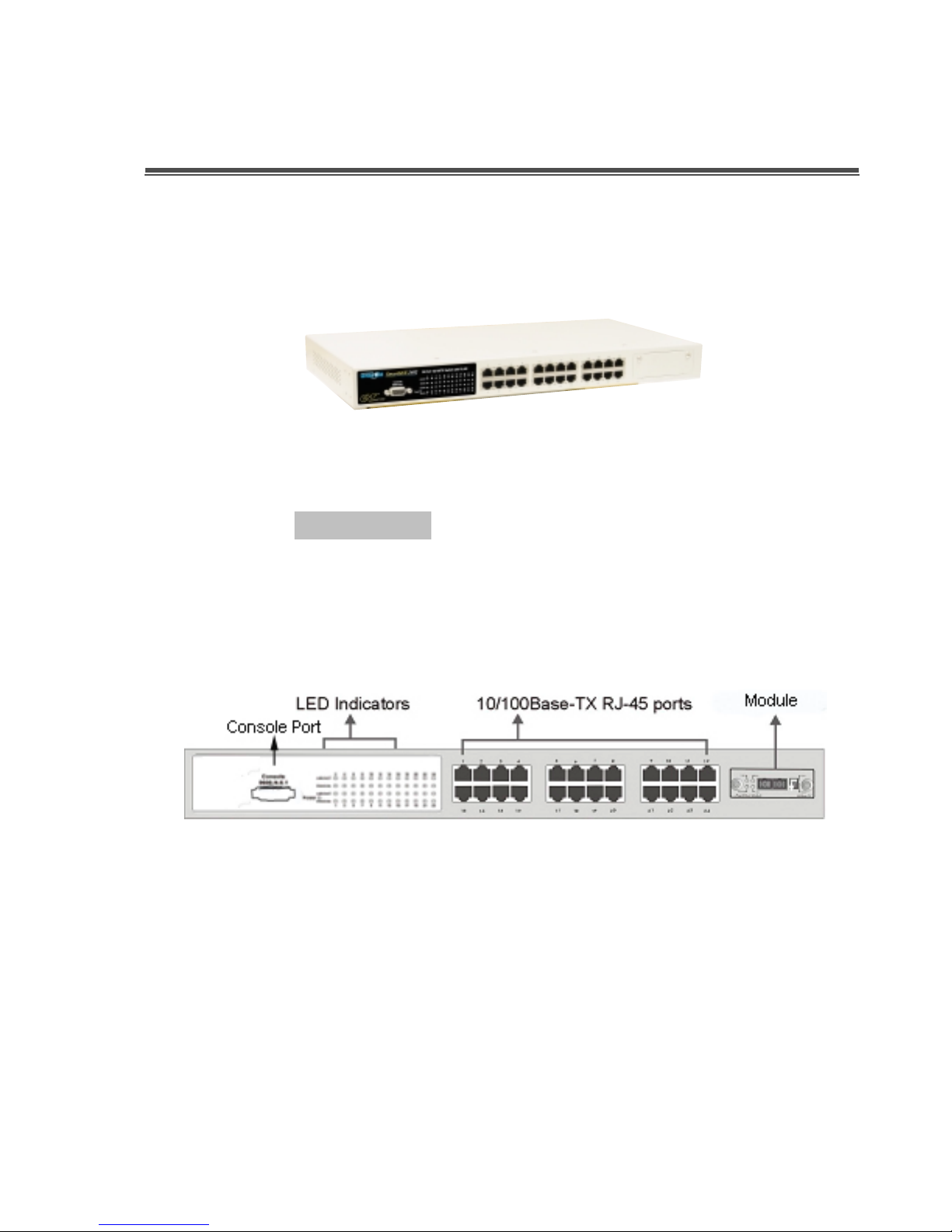
Front Panel
The Front Panel of the SmartGST-2402 consists of twenty-four 10/100Base-
TX RJ-45 ports (Auto MDI/MDIX) and one expansion slot. The LED Indicators
are also located on the front panel of the Switch.
Figure 2-1. The Front panel of SmartGST-2402
RJ-45 Ports (Auto MDI/MDIX): Twenty-Four 10/100 N-way auto-sensing for
10Base-T or 100Base-TX connections.
Module (Optional): 2 port 100Base-FX (SC/MM), 2 port 100Base-FX
(SC/SM), 2 port 100/1000Base-T, 2 port 1000Base-SX (SC/MM), or
1000Base-LX (SC/SM).
Page 10

LED Indicators
The LED Indicators give real-time information of systematic operation status.
The following table provides a description of LED status.
Figure 2-2. LED indicators
LED Status Description
Power
LNK/ACT
FDX/COL
Green
Off
Green
Blinks
Off
Orange
Blinks
Off
Table 2-1. The Description of LED Indicators
Power On
Power is not connected
The port is connecting with the device.
The port is receiving or transmitting data.
No device attached.
The port is operating in Full-duplex mode.
Collision of Packets occurs in the port.
in half-duplex mode
Rear Panel
Page 11
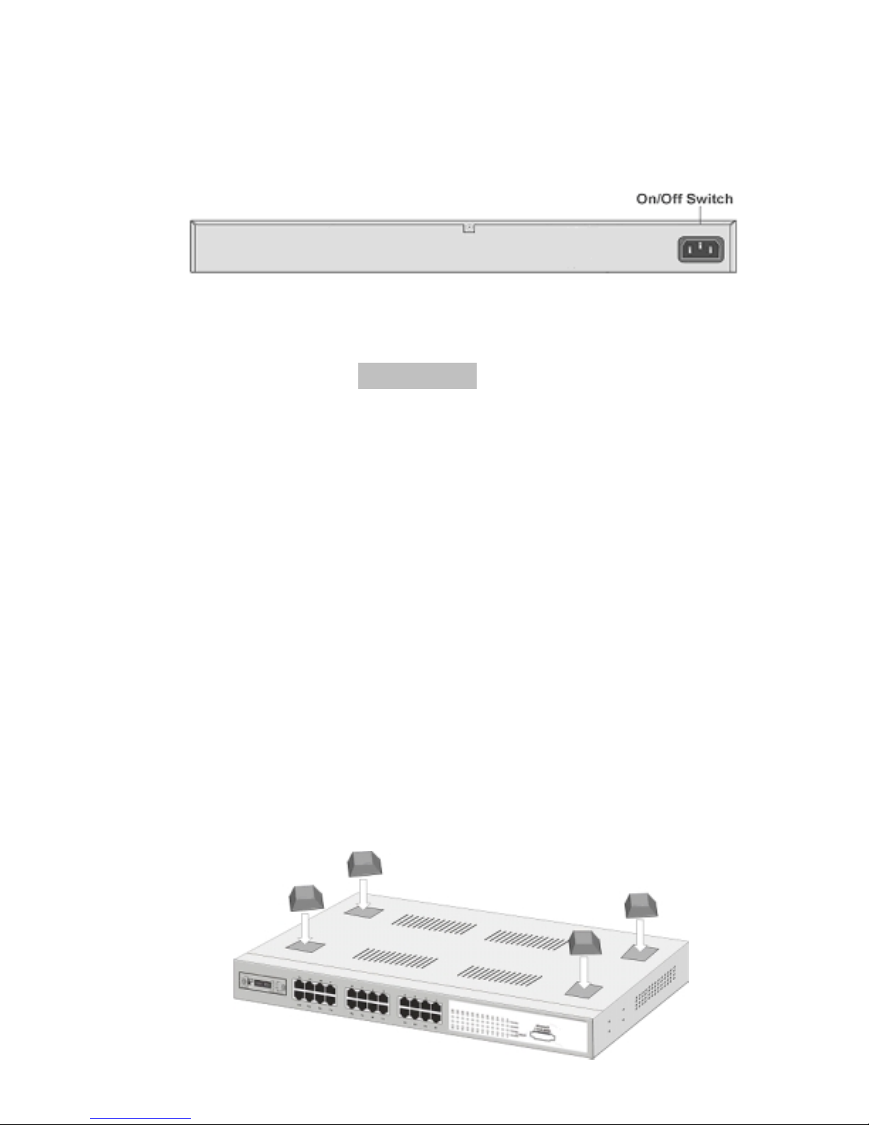
as shown in Figure 2-3. The Switch will work with AC in the range 100-240V
AC, 50-60Hz.
Figure 2-3. The Rear Panel of SmartGST-2402
Desktop Installation
Set the Switch on a sufficiently large flat space with a power outlet nearby.
The surface where you put your Switch should be clean, smooth, level and
sturdy. Make sure there is enough clearance around the Switch to allow
attachment of cables, power cord and allow air circulation.
Attaching Rubber Feet
A. Make sure mounting surface on the bottom of the Switch is grease and
dust free.
B. Remove adhesive backing from your Rubber Feet.
C. Apply the rubber feet to each corner on the bottom of the Switch. These
footpads can protect the Switch from shock/vibration.
Page 12
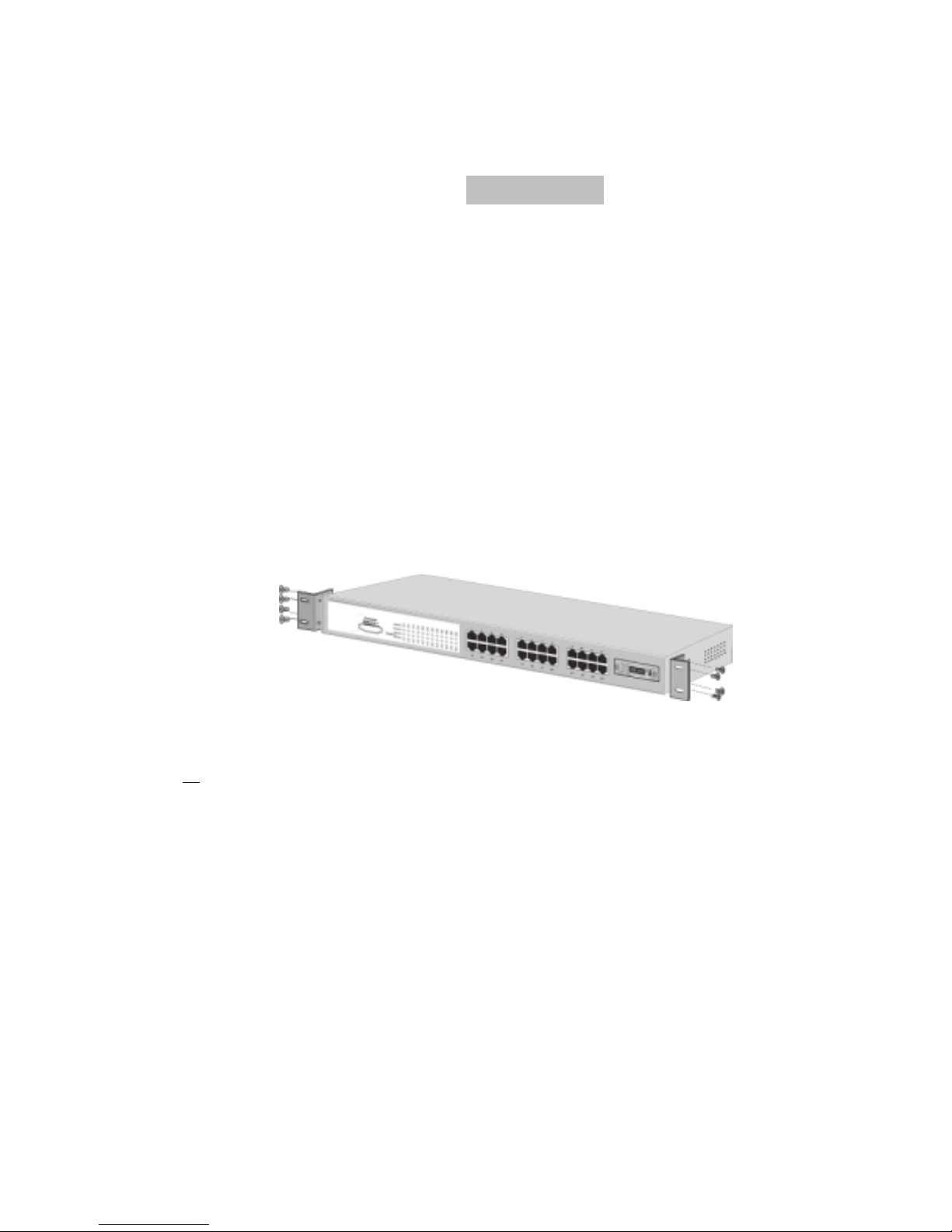
Rack-mounted Installation
The SmartGST-2402 comes with a rack-mounting kit and can be mounted in
any EIA standard size, 19" Rack. The Switch can be placed in a wiring closet
with other equipment.
Perform the following steps to rack mount the switch:
A. Position one bracket to align with the holes on one side of the switch and
secure it with the smaller bracket screws. Then attach the remaining
bracket to the other side of the Switch.
Figure 2-4. Attach mounting brackets with screws
B. After attaching mounting brackets, position the SmartGST-2402 in the
rack by lining up the holes in the brackets with the appropriate holes on
the rack. Secure the Switch to the rack with a screwdriver and the rack-
mounting screws.
Page 13
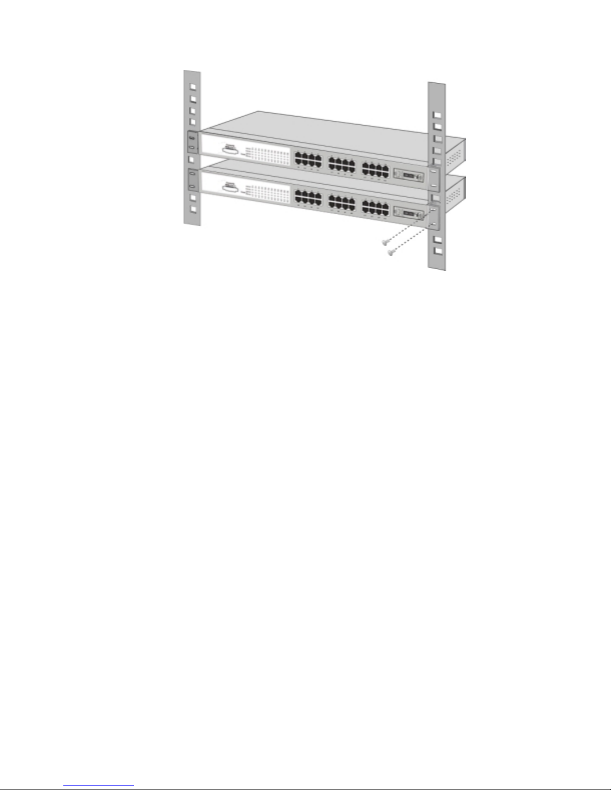
Figure 2-5. Mounting the Switch in an EIA standard 19" Rack
Note: For proper ventilation, allow about at least 4" (10 cm) of clearance on
the front and 3.4" (8 cm) on the back of the Switch. This is especially
important for enclosed rack installations.
Power On
Connect the power cord to the power socket on the rear panel of the Switch.
The other side of power cord connects to the power outlet. The internal power
supply of the Switch works with voltage range of AC in the 100-240VAC,
frequency 50~60Hz.
Check the power indicator on the front panel to see if power is properly
supplied.
Page 14

3. Network Application
This section provides a few samples of network topology in which the Switch
is used. The SmartGST-2402 is designed as a segment switch. With its large
address table (8k MAC address) and high performance, it is ideal for
interconnecting networking segments.
PC, workstations, and servers can communicate with each other by directly
connecting with SmartGST-2402. The switch automatically learns node
addresses, which are subsequently used to filter and forward all traffic based
on the destination address.
By using any port as an uplink port, the Switch can connect with another
switch or hub and interconnect other small-switched workgroups to form a
larger switched network. Switches can also be interconnected using the fiber
port. The distance between two switches via fiber cable can be up to 2
kilometers (Multi-Mode fiber) or 30 kilometers (Single Mode fiber).
Small Workgroup
The SmartGST-2402 can be used as a standalone switch to which personal
computers, servers, and/or printer servers, are directly connect to form a
small workgroup.
Page 15

Figure 3-1. Small Workgroup Application
Segment Bridge
This switch is an ideal solution for departmental users in corporate backbones
where large data broadcasts are constantly broadcast.
In the illustration below, two Ethernet switches with PCs, a print server, and a
local server are all connected to the Switch. All the devices in this network can
communicate with each other through the Switch. Connecting servers to the
Switch allow other users to access the data on server.
Page 16

10/100Mbps port
Print Server
Uplink to backbone switch
Giga port
Server
Figure 3-2. Department Bridge Application
Connecting to the Switch
The Console port is a female DB-9 connector that enables a connection to a
PC or terminal for monitoring and configuring the Switch. Use the supplied
RS-232 cable to connect a terminal or PC to the Console port.
The Console configuration (out of band) allows you to set the Switch for
"remote terminal" as if the console terminal were directly connected to it.
Page 17

4. Console Management
Login in the Console Interface
When the connection between Switch and PC is ready, turn on the PC and
run a terminal emulation program or Hyper Terminal and configure its
communication parameters to match the following default characteristics of
the console port:
Baud Rate: 9600 bps
Data Bits: 8
Parity: none
Stop Bit: 1
Flow control: None
Figure 4-1. The settings of communication parameters
After finishing the parameter settings, click “OK“. When the blank screen
shows up, press Enter key to bring out the console management main screen.
Then, press any key to enter the function management screen.
Page 18

Console main screen
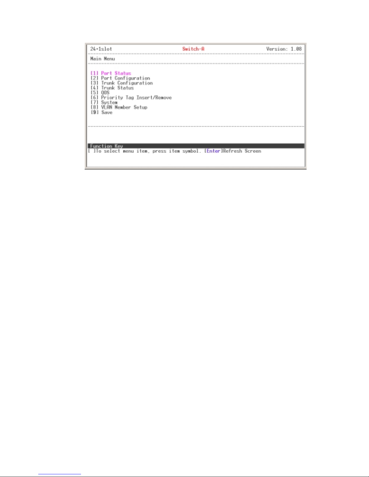
Main Menu
There are 8 selections as follow.
[1] Port Status: it displays status of the ports
[2] Port Configuration: configure the port status.
[3] Trunk Configuration: configure Trunk function.
[4] Trunk Status: display Trunk Link fault information and Network Loop
fault port detected information.
[5] QoS: configure QoS function and setup the ports priority.
[6] Priority Tag Insert/Remove: configure the ports tagging control
[7] System: enable VLAN function and broadcast storm filtering control,
setup the name of switch, and reset switch to default configuration.
[8] VLAN Member Setup: Configuring PortBase VLAN group.
[9] Save: save the configuration that user has made.
Page 19
Main menu line interface
Control Key description:
The control keys provided in all menus:
I/M/J/L: Move the vernier to up, down, left, and right.
Enter: Edit finish or OK in function screen.
Space: Toggle selected item to next configure or change the value.
0: to exit the current action mode.
E: to edit the parameter or configuration.
Space: to toggle state.
Enter: Refresh the screen display.
1/2: Up page and next page.
Page 20

Port Status
It displays the status of the ports. Enter the “1” to enter the Port Status
display interface. In the Port Status interface, using the “2” to view next page.
Using the “1” to go back to previous page.
Speed: display port connection speed.
Duplex: display port duplex mode.
Link: display port statuses link status. When the port is connecting with
the device and work normally, the link status is “UP”. Opposite is “Down”.
Flow Control: display the flow control status is “enable” or “disable”.
Auto Negotiation: display the auto negotiation status.
Trunk: display the port belongs in which trunk group if the port were
added into a trunk group.
Port Configuration
You can configure speed, status, flow control, Tx bandwidth, and Rx
bandwidth of each port using the control key to set up the configuration.
Port status interface
Page 21

Port configuration interface
oups default to disabled status. Use the “Space
e
Enable: enabling or disabling this port.
Speed advertisement: select speed and duplex mode of port.
Flow Control: enabling or disabling the Flow Control function.
Rx Bandwidth: set up the receive bandwidth.
Tx Bandwidth: set up the transceiver bandwidth.
[Note] You must to enable the Flow control for Rx/Tx bandwidth to work.
Trunk Configuration
It supports 8-trunk groups as follows:
Trunk1 Port 1, 2
Trunk 2 Port 3, 4
Trunk 3 Port 5, 6, 7, 8
Trunk 4 Port 9, 10, 11, 12
Trunk 5 Port 13, 14, 15, 16
Trunk 6 Port 17, 18, 19, 20
Trunk 7 Port 21, 22, 23, 24
Trunk 8 Port 25, 26
All trunk gr
” key to change th
Page 22

trunk status to “Enable”.
Trunk Configuration interface
Trunk Status
This window displays the trunk link warning information. When the trunking
group has detected an error, the information will be displayed in this section.
Trunk Status interface
Page 23

QoS
You can configure QoS functions.
TOS/Diff Serv. Priority: enabling or disabling TOS/Diff service priority.
802.1p Priority: enabling or disabling 802.1p priority function.
Priority Weight Ration (High: Low): select the priority weight ration
mode – 1:0, 4:1, 8:1, or 16:1. The default value is 16:1.
1:0: the switch will process all high priority packets.
4:1: the switch will process 4 high priority packet first, the process 1
low priority packet.
8:1: the switch will process 8 high priority packet first, the process 1
low priority packet.
16:1: the switch will process 16 high priority packet first, the process
1 low priority packet.
Force Set High Priority Port: set port to be high priority level
QoS configuration interface
Page 24
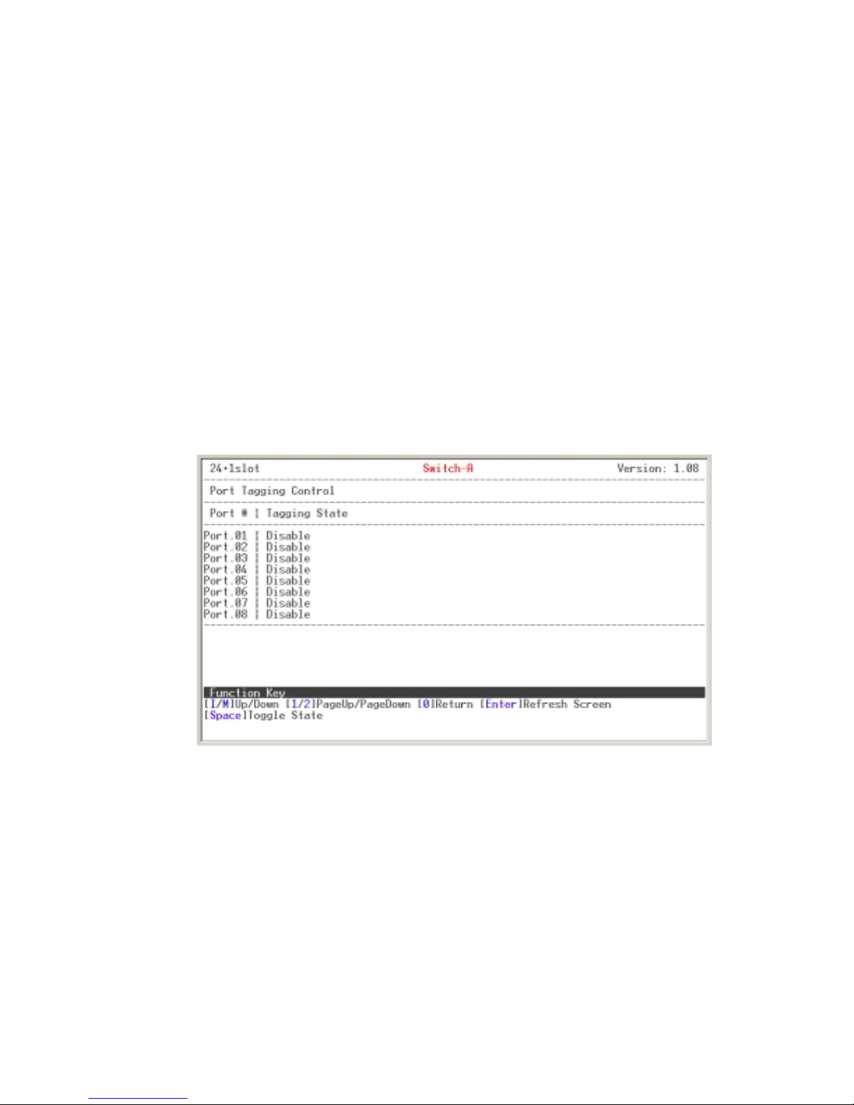
Priority Tag Insert/Remove
Sets each port's tagging control. There are four choices of port tagging
control:
Disable: No port tagging control on this port.
Remove tag: Removes the packet’s tag as the packet passes through
this port.
Insert Tag (high priority only): Inserts the packet’s tag as the packet
passes through the high priority port.
Insert Tag (All frame): Inserts the packet’s tag when the packet passes
through this port.
System
You can enable VLAN function and broadcast storm filtering control, set up
the name of the switch, and reset the switch to default value. Enter the
selection number to configure.
VLAN Function: enter “1” to change the value.
Priority Tag Insert/Remove interface
“
”
Page 25

name is "Switch-A".
Broadcast Storm Filtering Control: enter “3” to change the value.
Load Factory Default Setting: enter “1” to set the switch configuration
value to default value.
System interface
VLAN Member Setup
Configuring Port-Base VLAN group.
Add VLAN Group
1. Enter “E” to switch to Edit Mode.
2. Press “A” to start adding a VLAN group.
3. Use “L” and “J” to move to the port that you want to add into a VLAN
group and use “space” key to mark the port.
4. When finished selecting VLAN members, press “ U” to update the VLAN
table.
5. The VLAN group list will be displayed.
Page 26
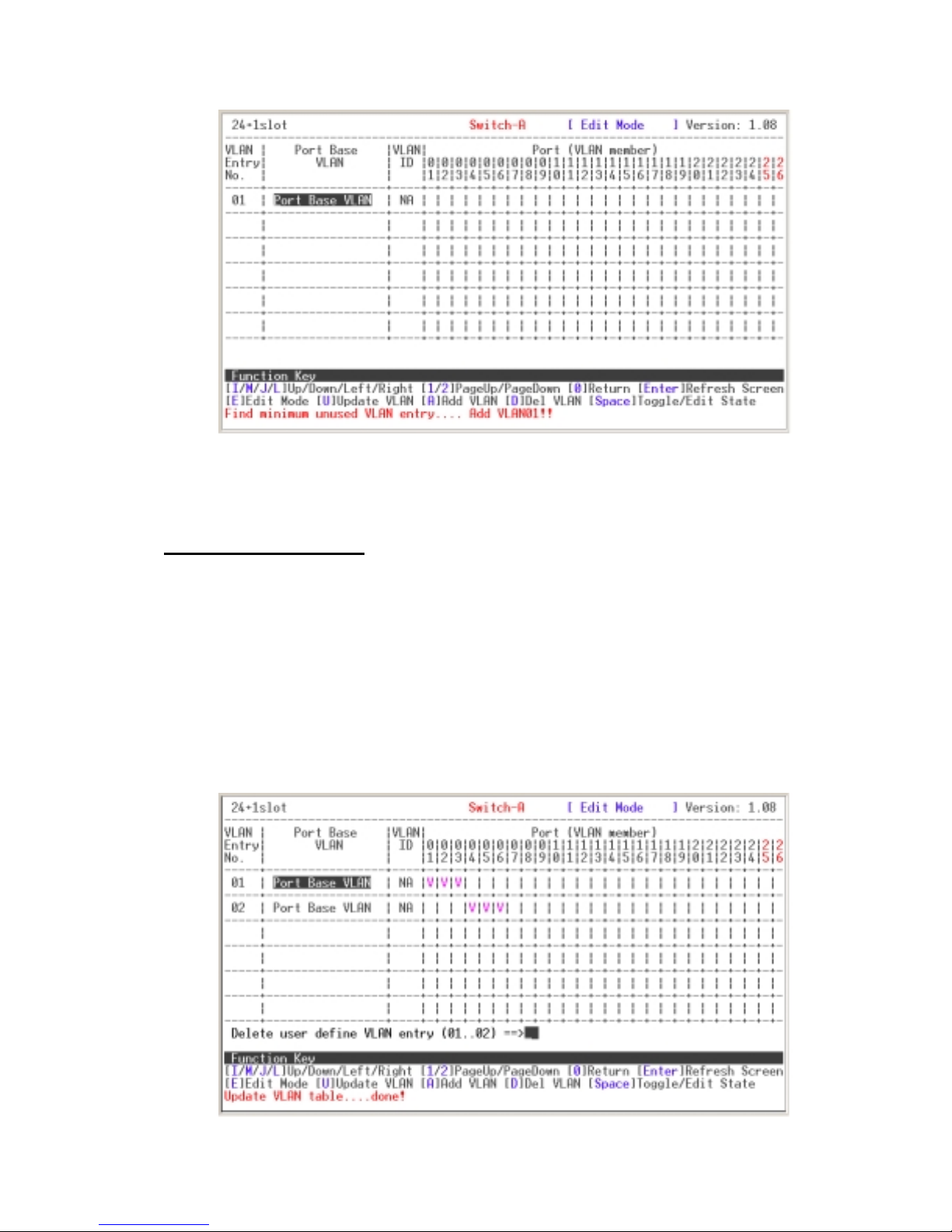
Add VLAN Group interface
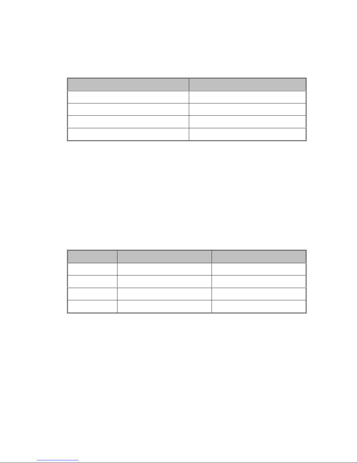
Delete VLAN Group
1. Press “E” to Edit mode.
2. Press “D” and enter the VLAN Entry No.
3. Press “ Enter”. The system will ask you to confirm the deletion. Enter “y”
to confirm the deletion.
4. Press “Enter” the VLAN group will be deleted.
5. Press “U” to update the VLAN information to system.
VLAN deletion interface
Page 27

Save
Save all configurations changes. Without saving the configuration, the new
setting will not take effect. If you turn off the device without saving the
configurations, all changes will be permanently lost
Page 28

5. Troubleshooting
This section is intended to help you solve the most common problems of the
SmartGST-2402.
Incorrect connections
These ports can auto-detect straight or crossover cables when you link this
switch with other Ethernet device. Always use the correct UTP or STP RJ-45
cable. 10/100Mbps ports (Fast Ethernet) use two pair cable and 1000T ports
(Gigabit Ethernet) use four pair cable. If the RJ-45 connector pins are not at
right position then the link will fail. For fiber connections, please notice that
fiber cable mode and fiber module should be match.
Faulty or loose cables
Look for loose or obviously faulty connections. If they appear to be OK, make
sure the connections are snug. If that does not correct the problem, try a
different cable.
Non-standard cables
Non-standard and miswired cables may cause numerous network collisions
and other network problem and can seriously impair network performance. A
Category 5 cable tester is a recommended tool for every 100Base-T network
installation.
Improper Network Topologies
It is important to make sure that you have a valid network topology. Common
topology faults include excessive cable length and too many repeaters (hubs)
Page 29

between end nodes. In addition, you should make sure that your network
topology contains no data path loops. Between any two ends nodes, there
should be only one active cabling path at any time. Data path loops will cause
broadcast storms that will severely impact your network performance.
Diagnosing LED Indicators
The Switch can be easily monitored through panel indicators to assist in
identifying problems, which describes common problems you may encounter
and where you can find possible solutions.
If the power indicator does turn on when the power cord is plugged in, you
may have a problem with power outlet, or power cord. However, if the Switch
powers off after running for a while check for loose power connections, power
losses or surges at power outlet. IF you still cannot resolve the problem,
contact your local dealer for assistance.
Cabling
RJ-45 ports: use unshielded twisted-pair (UTP) or shield twisted-pair ( STP )
cable for RJ-45 connections: 100_ Category 3, 4 or 5 cable for 10Mbps
connections or 100_ Cat-5 or Cat-5e cable for 100Mbps connections. Also be
sure that the length of any twisted-pair connection does not exceed 100
meters (328 feet). Gigabit port should use Cat-5e or cat-6 cable for 1000Mbps
connections. The length does not exceed 100 meters. For more information
please refer to Appendix section.
Page 30

6. Technical Specification
This section provides the specifications of SmartGST-2402, and the following
table lists these specifications.
IEEE802.3 10BASE-T
IEEE802.3u 100BASE-TX/100BASE-FX
IEEE802.3ab 1000BASE-T
Standard
LED Indicators
IEEE802.3z Gigabit fiber
IEEE802.3x Flow control and Back pressure
IEEE802.3ad Port Trunk
IEEE802.1p Class of service
System: power
10/100Base-TX: Link/Activity, Full Duplex/Collision
100FX: Link/Activity, Full Duplex
Gigabit SX/LX: Link/Activity
1000Base-T: 100, 1000, Link/Activity, Full
Duplex/Collision
10/100TX: 24 x RJ-45
100FX(Multi mode) module: 1 or 2 x SC/MT-RJ
Connector
Switch architecture Store and Forward
Back-plane 8.8Gbps with full wire speed
MAC address 8K Mac with Auto Learning
Memory 2.5Mbits
100FX(Single mode) module: 1 or 2 x SC
Gigabit SX module: 2 x SC.
Gigabit LX module: 2 x SC.
1000T module: 2 x RJ-45
Page 31

Power 100~240VAC 50/60Hz
Power Consumption 20Watts(Maximum)
Dimensions 440mm x 161mm x 44mm (L x W x H)
EMI & Safety FCC Class A, CE, UL, cUL, CE/EN60950
Page 32

Appendix
Console Port Pin Assignments
The DB-9 serial port on the front panel is used for out-of-band console
configuration. The menu-driven console configuration program can be
accessed from a terminal or a PC running a terminal emulation program. The
pin assignments used to connect to the serial port are provided in the
following tables:
Figure 6-1. DB-9 Console Port Pin Numbers
DB-9 Port Pin Assignments
EIA Circuit CCITT Signal Description
RxD
BB 104
BA 103
AB 102
(Received
Data)
TxD
(Transmitted
Data)
SGND
(Signal
Ground)
Switch’s
DB9 DTE
Pin #
22
33
55
PC DB9
DTE Pin #
Page 33

Console Port to 9-Pin DTE Port on PC
9-Pin
Serial Port
2 RXD <---------RXD ------------ 3 TxD
3 TXD -----------TXD ----------> 2 RxD
5 SGND -----------SGND ---------- 5 SGND
CCITT Signal
PC’s 9-Pin
DTE Port
Cables
The RJ-45 ports on the switch support automatic MDI/MDI-X operation, so
you can use standard straight-through or crossover twisted-pair cables to
connect to any other network device (PCs, servers, switches, routers, or
hubs). Please refer to the following table for cable specifications:
Cable Types and Specifications
Cable Type Max. Length Connector
Cat. 3, 4, 5
10BASE-T
100-ohm UTP
Cat. 5 100-ohm
100BASE-TX
UTP
50/125 or 62.5/125
micron core
100BASE-FX
multimode fiber
(MM)
Cable specification table
100 m (328 ft) RJ-45
100 m (328 ft) RJ-45
2 km (1.24 miles) SC or ST
100BASE-TX/10BASE-T Pin Assignments
With a 100BASE-TX/10BASE-T cable, pins 1 and 2 are used for transmitting
Page 34
data while pins 3 and 6 are used for receiving data.
RJ-45 Pin Assignments
Pin Number Assignment
1 Tx+
2 Tx-
3 Rx+
6 Rx-
Note: “+” and “-” signs represent the polarity of the wires that make up each
wire pair.
All ports on this switch support automatic MDI/MDI-X operation. In straight-
through cables, pins 1, 2, 3, and 6, at one end of the cable, are connected
straight through to pins 1, 2, 3 and 6 at the other end of the cable. The table
below shows the 10BASE-T/ 100BASE-TX MDI and MDI-X port pin outs:
Pin MDI-X Signal Name MDI Signal Name
1 Receive Data plus (RD+) Transmit Data plus (TD+)
2 Receive Data minus (RD-) Transmit Data minus (TD-)
3 Transmit Data plus (TD+) Receive Data plus (RD+)
6 Transmit Data minus (TD-) Receive Data minus (RD-)
 Loading...