

Page 1
CB-320
TWO-WAY CB RADIO
3WAT T
INSTRUCTION
MANUAL
6KM
*
Page 2

CONTENTS
SAFETY INFORMATION .................. 3
IMPORTANT INFORMATION
CONCERNING UHF CB RADIO ........ 3
POSSIBLE ISSUES .................................. 3
EMERGENCY CHANNELS ...................... 4
TELEMETRY CHANNELS ........................4
IMPORTANT ADVICE ....................... 4
SUPPLIED WITH .............................. 5
OPTIONAL ACCESSORIES ............... 5
FEATURES....................................... 6
CONTROLS ..................................... 7
LCD ICONS ..................................... 8
CHARGING THE BATTERY ............... 9
TO REMOVE THE BATTERY PACK ........... 9
TO REFIT THE BATTERY PACK ................9
CHARGING THE CB-320
SINGLE UNIT ...................................... 10
CHARGING THE BATTERY PACK .......... 10
BATTERY USAGE ........................... 11
BATTERY LOW ALERT .......................... 11
CONSERVING BATTERY POWER .......... 11
STANDBY MODE ................................ 11
USING CTCSS/DCS ............................. 11
SCANNING ........................................11
LOW TRANSMIT POWER SETTINGS ..... 12
BASIC OPERATION ....................... 12
POWER ON/OFF ................................. 12
ADJUSTING THE VOLUME ...................12
DISPLAY LIGHTING .............................12
RECEIVING SIGNALS .......................... 12
TRANSMITTING .................................. 13
SELECTING CHANNELS ....................... 13
SQUELCH ........................................... 13
KEYPAD LOCK .................................... 13
DUPLEX OPERATION ..........................13
SCANNING ................................... 14
TO ADD OR REMOVE
SCAN CHANNELS ............................... 14
TO SCAN ............................................15
SCANNING FEATURES ........................15
CTCSS AND DCS ........................... 15
MENU ........................................... 16
USING THE MENU .............................. 16
FM RADIO ..........................................16
BUTTON BEEP ....................................17
INSTRUCTION MANUAL
CB-320
PAGE
1
Page 3

SQUELCH LEVEL SETTING ................... 17
TRANSMITTER POWER ....................... 17
VOX SETTINGS ...................................18
POWER ON MESSAGE ........................ 18
RECEIVER (TRANSMITTER)
CTCSS/DCS CODES ............................. 19
KEYPAD LOCK .................................... 19
TO ADD OR REMOVE
SCAN CHANNELS AND
TO START SCANNING ......................... 20
DUPLEX MODE SELECTION ................. 20
CTCSS TONE FREQUENCIES .......... 21
DCS TONE CHART ......................... 21
UHF CB OPERATING
FREQUENCIES .............................. 23
SPECIFICATION ............................ 24
CONTRACT WARRANTY
AGAINST DEFECTS ....................... 25
SAFETY INFORMATION
The CB-320 is a radio transmitting device.
yWhen transmitting, keep the antenna more than 25 mm from any part of the head
or body.
yDo not transmit near electrical blasting equipment or in explosive atmospheres.
yDo not allow children to operate a radio transmitter unsupervised.
IMPORTANT INFORMATION CONCERNING UHF CB RADIO
The use of the Citizen Band radio service is licensed in Australia by the ACMA Radio
communications (Citizens Band radio Stations) Class Licence and in New Zealand by
the Ministry of Economic Development New Zealand (MED). A General User Radio
Licence for Citizens Band radio and operation is subject to conditions contained in
those licences.
The class licence for users and equipment operating in the CB/PRS 477 MHz band
has been amended. This radio meets the new 80 channel standard.
In simple terms the same amount of spectrum is available; however, radio transceivers can now operate in a narrower bandwidth and hence use less spectrum. These
radios are generally referred to as narrowband or 12.5 kHz radios. By using 12.5 kHz
channel spacing instead of 25 kHz, the 40 channels originally allocated can now be
expanded to 80 channels thereby doubling the channel capacity and relieving congestion in the UHF CB/PRS band.
Original 40 channel wideband radios will continue to operate on the original 40
channels, however they will not be able to converse on the newer channels 41 –
80. The newer narrowband radios will be able to converse with all older 40 channel
wideband radios on all channels 1 – 40 as well as the newer channels allocated
from 41 – 80.
The mixing of narrowband and wideband radios in the same spectrum can cause
some possible operating issues of interference and varying levels of received volume.
PAGE 2
INSTRUCTION MANUAL
CB-320
POSSIBLE ISSUES
When a new narrowband radio receives a transmission from an older wideband radio
the speech may sound loud and distorted – simply adjust your radio volume for best
performance.
INSTRUCTION MANUAL
CB-320
PAGE
3
Page 4

When an older wideband radio receives a signal from a new narrowband radio, the
speech may sound quiet – simply adjust your radio volume for best performance.
Depending on how close your receiving radio is to another transmitting radio, there
can be interference from the transmitting radio if it is using a channel adjacent to the
channel you are listening to. Simply try going up or down a few channels from the
currently selected channel.
The above situations are not a fault of the radio but a symptom of operating wideband and narrowband radios in the same bandwidth. This possible interference will
decrease over time as the population of wideband radios ages and decreases.
Further information and updates are available from the Australian Communications
and Media Authority (ACMA) at
Development (MED), Radio Spectrum Management at:
EMERGENCY CHANNELS
The ACMA has allocated channels 5/35 for emergency use only. Channel 5 is the
primary Simplex Emergency Channel. Where a channel 5 repeater is available, you
should select Duplex on channel 5.
Channel 35 is the input channel for the channel 5 repeater therefore channel
NOTE:
35 should also not be used for anything other than emergency transmissions.
TELEMETRY CHANNELS
ACMA regulations have allocated channels 22 and 23 for telemetry-only applications
and have prohibited the transmission of speech on these channels. Consequently the
radio has a transmit-inhibit applied to channels 22 and 23.
In the event that additional telemetry/telecommand channels are approved by the
ACMA, these channels shall be added to those currently listed where voice transmission is inhibited. Currently, transmissions on channels 61, 62 and 63 are also inhibited and these channels are reserved for future allocation.
www.acma.gov.au
and the Ministry of Economic
www.rsm.govt.nz
IMPORTANT ADVICE
READ ALL INSTRUCTIONS
and retain this manual for future reference.
connect the radio to a power source other than the supplied battery. This
NEVER
y
may damage your radio.
carefully and completely before operating your radio
y
y
y
y
y
y
y
y
place your radio in front of a vehicle airbag.
DO NOT
use your radio with a damaged antenna.
DO NOT
attempt to modify your radio in any way.
DO NOT
charge your radio at normal room temperature.
ALWAYS
switch off your radio where notices restrict the use of two–way radio or
ALWAYS
mobile telephones.
use Unicom approved rechargeable battery packs with the supplied char-
ONLY
ger.
storing or charging your radio in direct sunlight.
AVOID
storing or using your radio where temperatures are below -20°C or above
AVOID
+60°C.
SUPPLIED WITH
yCB-320 radio
yBelt clip
yLi-ion battery pack (1300 mAh)
yAC adaptor
yDesktop Charger
yEar piece
yInstruction Manual
yHang Strap
OPTIONAL ACCESSORIES
yUSB 12V/24V vehicle charger (AC001)
yWaterproof carry case (AC003)
ySpeaker microphone (AC007)
yClear acoustic tube and lapel microphone (AC002)
PAGE 4
INSTRUCTION MANUAL
CB-320
INSTRUCTION MANUAL
CB-320
PAGE
5
Page 5
FEATURES
TRANSMIT (TX)
3.0/1.0 watt RF power:
tery power when transmitting in close range by using the Low Power setting.
Duplex function:
VOX SETTINGS:
RECEIVE (RX)
80 channels 477 MHz UHF CB
UHF CB radio.)
Power Save feature:
tivity.
Signal receive indicator
Programmable scan function:
SQUELCH:
Used to eliminate the background noise when there are no signals pres-
ent.
PRIVACY FUNCTIONS
CTCSS & DCS:
A built-in Continuous Tone Coded Squelch System and a Digital Cod-
ed Squelch option provide quiet channel operation.
USER CONTROLS AND INTERFACE
Keypad Lock:
Backlit LCD:
Prevents accidental button presses.
For night viewing.
Selectable transmitter power allows you to conserve bat-
Only those individual channels in your area that have repeaters.
The VOX feature allows you to have hands-free conversations.
(Refer to Page 3. Important information concerning
Conserves battery power by sleeping during periods of inac-
Scans up to 80 UHF CB channels.
E
F
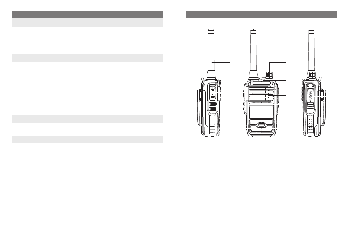
Antenna
A
PTT (Push to Talk)
B
F1 (LED/SCAN)
C
F2 (Radio/Emergency)
D
Belt Clip
E
Battery Pack
F
CONTROLS
A O
B
C
D
H
G
MENU UP
V/M
DOWN
EXIT
Menu/Confirm
G
Exit/Cancel/Lock
H
Down
I
Up
J
LCD Display
K
MIC
L
P
N
M
L
K
J
I
M
N
O
P
Q
Q
Speaker
Indicator LED
Power/Volume
LED Flashlight
Accessory Jack
PAGE 6
INSTRUCTION MANUAL
CB-320
Short press to turn the LED ON/OFF. Long Press (1s) to turn Scanning ON/OFF.
F1:
Short press to turn FM radio ON/OFF. Long Press (1s) to activate Emergency Alarm.
F2:
Alarm sound will stay ON and transmit through CH5. Turn the power OFF to stop
this.
INSTRUCTION MANUAL
CB-320
PAGE
7
Page 6

LCD ICONS
A
B C D E
FM NAR LOW VOX SCN
L K J I H G
50
25
75
CHARGING THE BATTERY
The CB-320 is powered by a 3.7V Li-ion battery pack. The battery pack should be fully
charged before being used for the rst time or if you have not used the radio for some
time. This will ensure maximum capacity is available.
TO REMOVE THE BATTERY PACK
1. Ensure that your radio is switched off.
2. Hold the radio horizontally upside-down.
F
3. Using your ngernail, open the battery lock towards the rear of the radio to release
the battery, then pull the battery up. The battery pack should separate from the radio.
Channel Number/Menu Option:
A
lected menu option.
Key Lock Icon:
B
Appears when the selected channel has DCS code enabled.
DCS:
C
CTCSS:
D
Battery Icon:
E
Channel Display/Menu Option:
F
ed menu option.
F
Appears on channels where Duplex is enabled.
:
G
Appears on channels where Scan is enabled.
SCN:
H
Appears when VOX mode is active.
VOX:
I
Appears when Low TX power (1W) is selected. Otherwise, High TX (3W) power.
LOW:
J
Unit is running on narrow band.
NAR:
K
Appears when in FM radio mode.
FM:
L
PAGE 8
Appears when the keypad is locked.
Appears when the selected channel has CTCSS code enabled.
Displays battery charge level.
Displays the selected channel in use or the se-
Displays the selected channel in use or the select-
INSTRUCTION MANUAL
CB-320
TO REFIT THE BATTERY PACK
1. Ensure that your radio is switched off.
2. Align the slots in the battery pack with the battery guides on the back of the radio.
3. Slide the battery pack inwards as far as it will go, push down the back of the battery
pack then lock it.
INSTRUCTION MANUAL
CB-320
PAGE
9
Page 7

CHARGING THE CB-320 SINGLE UNIT
The CB-320 is supplied with a 240V Ac adaptor. The Ac adaptor will charge a fully discharged 1300mAh battery pack to full capacity in around 4 hours.
To charge the radio
1. Plug the Ac adaptor into a 240V Ac outlet
2. Plug the micro USB connector into the charging socket on the back of the desktop
charger.
3. Put the CB-320 into the desktop charger as picture below.
Ensure that your radio is switched off.
NOTE:
The radio will begin charging. During this time the desktop charger’s LED will light RED.
Once the battery is fully charged, the indicator LED will change to GREEN.
CHARGING THE BATTERY PACK
While the battery is charging, the indicator LED on the desktop charger will light
NOTE:
red. Once the battery is fully charged, the desktop charger’s indicator LED will
change to Green.
BATTERY USAGE
The time taken to discharge the battery pack will depend on how you use the radio. The
battery pack supplied is powerful enough for up to 20 hours of use under average conditions using low power.
BATTERY LOW ALERT
When the battery icon blinks on the radio’s display, the battery level is low and the battery pack should be recharged.
CONSERVING BATTERY POWER
The radio has built-in power saving features to help you get the maximum amount of
time between charges from your li-ion battery pack. If you need to operate your radio in
a situation where you require maximum battery life (e.g. a remote site where there is no
convenient recharging facility nearby) the following hints can greatly reduce the amount
of power drawn from the battery pack.
STANDBY MODE
The radio will automatically enter the ‘standby’ mode when it is inactive (i.e. not transmitting or receiving signals).
While in standby mode it will still check for incoming signals but it will draw considerably
less power from the battery pack. As soon as a signal is heard or the keys are pressed
the radio will ‘wake up’ again. This standby mode is automatic and by itself can extend
the battery life by many hours.
USING CTCSS/DCS
If you are expecting to receive signals on a busy channel, you can program that channel
for CTCSS/DCS operation and get the other person to call you using the same CTCSS/
DCS tone. Your radio will then remain in standby and ignore all other signals until your
selected CTCSS/DCS tone is received.
PAGE 10
INSTRUCTION MANUAL
CB-320
SCANNING
The radio draws more power from the battery pack when scanning than when monitoring a single channel. This is because it must ‘wake up’ more often to monitor each
channel for activity. In addition, scanning increases the chance of nding a signal thereby
keeping the receiver ‘awake’ and the squelch open more often.
INSTRUCTION MANUAL
CB-320
PAGE
11
Page 8

LOW TRANSMIT POWER SETTINGS
The transmitter has both high and low power settings. If you are only operating over
short distances, are in a reasonably high location or are close to a local repeater, try
using the low transmitter power setting. This reduces the transmitter power to 1 watts
which increases the talk time available.
BASIC OPERATION
POWER ON/OFF
Rotate the Volume control clockwise past the ‘click’ to turn the radio on. Rotate the Volume control counter-clockwise past the click to turn the radio off again.
ADJUSTING THE VOLUME
With the unit powered on, rotate the Volume control clockwise to increase the volume
and counter-clockwise to decrease the volume.
DISPLAY LIGHTING
The LCD backlighting activates automatically whenever one of the four keys on the front
face panel is pressed and turns off automatically after 10 seconds.
RECEIVING SIGNALS
When a signal is received, the LED indicator on the upper center of the radio will light
BLUE. Adjust the Volume control for a comfortable listening level.
If the incoming signal is encoded with a CTCSS or DCS tone matching the one set in your
radio, you will be able to hear the signal in the speaker. If the LED indicator lights BLUE
but you cannot hear the signal, it is likely that the incoming signal is using a different
CTCSS or DCS tone to that selected in your radio (see menu options for more details on
setting CTCSS/DCS tones).
If the selected channel in your radio is not using a CTCSS/DCS tone but the in-
NOTE:
coming signal is encoded with a CTCSS/DCS tone, your radio will still be able to
listen.
If no further signals are received, the unit will return to standby mode after a few seconds.
PAGE 12
INSTRUCTION MANUAL
CB-320
TRANSMITTING
To transmit, press and hold the
PTT (Push-to-talk)
switch. The other radio you are
talking to must be set to the same channel. Hold the radio approximately 5 – 8 cm from
your mouth with the antenna vertical and speak into the built-in microphone.
While the
light RED. When you have nished speaking, release the
switch is pressed, the LED indicator on the upper center of the radio will
PTT
switch to receive incoming
PTT
signals (it is not possible to transmit and receive at the same time). If no further signals
are received, the unit will revert to standby mode.
SELECTING CHANNELS
In the ‘standby’ mode, press the UP key to step up one channel or the
step down one channel. Press and hold the UP or
keys to quickly scroll through
DOWN
DOWN
key to
the channels.
SQUELCH
The Squelch is used to eliminate the background noise when there are no signals present. The Squelch sensitivity (5) is preset in the Menu – SQL (see Menu options for more
details on setting the Squelch sensitivity).
KEYPAD LOCK
The Keypad Lock disables the keys to prevent accidental key presses from changing the
preferred settings of the radio. When the keys are locked, the icon “
the 4 front keys will be locked. The
To lock the Keypad press and hold the
To cancel the Keypad Lock, press and hold the
and the 2 side keys remain unlocked.
PTT
key. The icon “ “ will appear on the display.
EXIT
key. The icon “ “ will disappear.
EXIT
“ is displayed and
DUPLEX OPERATION
Duplex operation allows the radio to transmit on a different frequency to that which it
receives. This allows operation through repeater stations in your area. Repeaters automatically re-transmit your signal over a much wider area, providing greatly increased
range. The Duplex mode only works on designated repeater channels 1 – 8 and 41 – 48.
With Duplex selected on one of these channels, your radio actually transmits 30 channels
higher than it receives.
e.g. If Duplex is selected on channel 1, your radio will receive on channel 1 but will transmit on channel 31.
INSTRUCTION MANUAL
CB-320
PAGE
13
Page 9

Duplex can be enabled or disabled on individual channels. When Duplex is enabled on
the selected channel,
F
is displayed.
The Duplex mode is set through the Menu. Please refer to the Menu options further belo w.
Simplex/Duplex Range Comparison
SCANNING
Channel scanning allows you to monitor all channels for incoming signals.
While the radio is scanning, by pressing the
NOTE:
ning or pressing the
UP/DOWN
key will change the scan direction.
MENU/EXIT
TO ADD OR REMOVE SCAN CHANNELS
By default, all channels are in the scan memory.
NOTE:
1. Press the UP or DOWN keys to select the desired channel. Channels with the icon
SCN visible are already in the scan memory while those that do not display the icon
are not presently stored in the scan memory.
2. When the desired channel is displayed, press
MENU again and select
to add the selected channel to the scan memory or
ADD
MENU
to remove it from the scan memory.
key will stop the scan-
, go to option “
SC.ADD
”, press
DEL
TO SCAN
Press and hold the F2 key for 2 seconds, then channel numbers will change as the radio
scans through the channels. To change the scan direction while scanning, briey press
or
UP
To stop scanning, briey press
DOWN
.
then the radio will return to normal operation.
EXIT
SCANNING FEATURES
yIf a signal is received, the scan is paused allowing you to transmit and receive on that
channel. Once the channel has been inactive for 5 seconds the scan will automatically
resume.
yPressing the
switch while the radio is scanning will stop the scanning and start
PTT
to transmit on that channel. The scan will not resume.
yIf the scan is paused on a busy channel that you don’t wish to listen to, press the UP
or
keys to ‘skip’ over the channel and continue scanning after 5 seconds.
DOWN
The Scan mode will reduce the overall battery life because the Standby (battery sav-
TIP:
er) feature is overridden. If the battery is running low you should avoid scanning to
conserve power.
CTCSS AND DCS
CTCSS (Continuous Tone Coded Squelch System) and DCS (Digital Coded Squelch) are
similar Squelch quieting systems that allow groups of users to share the same channel
without disturbing each other. The CTCSS system uses 1 of 50 low frequency tones to
open and close the Squelch on the radio. The DCS system is similar to CTCSS but uses 1
of 104 digital codes to control the Squelch. When CTCSS or DCS is enabled on your radio, only signals that are using the same code as your radio will be heard in the speaker
and the Squelch will remain closed to all other signals.
CTCSS and DCS codes do not prevent others from hearing your transmission.
NOTE:
CTCSS/DCS tones are switched off by default. To use CTCSS/DCS you must rst enable
a suitable CTCSS/DCS code using the Menu (see Menu options for more details). Your
choice of CTCSS or DCS will largely depend on which is currently being used by other
radios in your group. If neither system is currently in use, you can make your own choice.
There is no difference in performance between the two systems. Once a CTCSS or DCS
code has been enabled, the display will show
CT
(for CTCSS) or
DCS
(for DCS).
PAGE 14
INSTRUCTION MANUAL
CB-320
INSTRUCTION MANUAL
CB-320
PAGE
15
Page 10

MENU
The menu key is used to set the various feature settings. The following chart shows the
order of these selections.
# Description Symbol Options
00 FM Radio (87–108Mhz)
UP/DOWN
01 Button Beep selection ON/OFF
02 Squelch level setting 0 - 9
03 Transmitter Power (default HIGH, no symbol)
04 VOX settings
05 Power on message MSG/DC/OFF
06 Receiver CTCSS/DCS
07 Transmitter CTCSS/DCS
08 Keypad Lock
09 To add or remove scan channels
10 To start the scanning
11 Duplex (channels 1 – 8 and 41 – 48 only)
CTCSS/DCS and transmit power settings are inhibited on channels 5/35 (emer-
NOTE:
gency channel).
USING THE MENU
To access the Menu, press the
MENU
listed above. Press MENU again to enter the selected option then
it. Press
to conrm the change or
MENU
FM RADIO
To listen the FM broadcast radio range from 87Mhz – 108Mhz. While in the FM radio
mode, press
UP/DOWN
to change the radio frequency.
to change
FM
LOW
VOX
CT/DCS
CT/DCS
SCN
F
ON/OFF
HIGH/LOW
ON/OFF
OFF/01 – 50/
001 - 208
OFF/01 – 50/
001 - 208
MANU/5 – 30
ADD/DEL
ON/OFF
key then the menu options will appear in the order
EXIT
to go back.
UP/DOWN
to change
To go to FM Radio Mode
1. Press the
2. Press
UP/DOWN
3. Press
MENU
key to enter the menu option.
MENU
repeatedly until ‘RADIO’ is displayed (Option #00).
to enter the selected option and
UP/DOWN
to change the frequency.
BUTTON BEEP
The Button Beep allows the radio to sound a conrmation beep whenever the keys are
pressed.
To Turn the Button Beep ON or OFF
1. Press the
2. Press
UP/DOWN
3. Press
MENU
4. Press
MENU
5. Press
EXIT
key to enter the menu option.
MENU
repeatedly until ‘BEEP’ is displayed (Option #01).
to enter the selected option and
UP/DOWN
to conrm the change and store your selection.
to go back to standby.
to select ‘ON’ or ‘OFF’.
SQUELCH LEVEL SETTING
The squelch is designed to keep the radio quiet when there are no signals present. The
squelch setting adjusts the sensitivity of the squelch to incoming signals. Higher squelch
settings require stronger signals to overcome the squelch and be heard in the speaker
while lower settings allow much weaker signals to be heard.
To set the Squelch
1. Press the
2. Press
UP/DOWN
3. Press
MENU
key to enter the menu option.
MENU
repeatedly until ‘SQL’ is displayed (Option #02).
to enter the selected option and
UP/DOWN
to adjust the Squelch level
from 0 (most sensitive) to 9 (least sensitive). (We recommend level 5).
4. Press
5. Press
to conrm the change and store your selection.
MENU
to go back to standby.
EXIT
TRANSMITTER POWER
The transmitter power can be set to High (default, no symbol on LCD) or low (LCD displays
). The power setting applies to the selected channel.
LOW
PAGE 16
INSTRUCTION MANUAL
CB-320
INSTRUCTION MANUAL
CB-320
PAGE
17
Page 11

1. Press the
2. Press
UP/DOWN
3. Press
MENU
4. Press
MENU
5. Press
EXIT
key to enter the menu option.
MENU
repeatedly until ‘POWER’ is displayed (Option #03).
to enter the selected option and
UP/DOWN
to conrm the change and store your selection.
to go back to standby.
to change the setting.
VOX SETTINGS
The VOX feature allows you to have hands-free conversations. When you speak, the microphone automatically detects your voice (or other nearby sound) causing the radio to
transmit without the need to press the PTT.
To enable VOX operation
1. Press the
2. Press
UP/DOWN
3. Press
MENU
4. Press
MENU
5. Press
EXIT
key to enter the menu option.
MENU
repeatedly until ‘VOX.SWI’ is displayed (Option #04).
to enter the selected option and
UP/DOWN
to conrm the change and store your selection.
to go back to standby.
to select ‘ON’ or ‘OFF’.
When VOX is enabled, the icon VOX is visible on the display.
Using the radio in a noisy environment with the VOX set to ON could cause the
NOTE:
radio to transmit unexpectedly. If this happens simply turn the VOX OFF.
POWER ON MESSAGE
You have the options to select what to display when power on. A welcome message,
Voltage or keep it blank.
To change the power on message
1. Press the
2. Press
UP/DOWN
3. Press
MENU
4. Press
MENU
key to enter the menu option.
MENU
repeatedly until ‘POW.MSG’ is displayed (Option #05).
to enter the selected option and
UP/DOWN
to conrm the change and store your selection.
to change the setting.
RECEIVER (TRANSMITTER) CTCSS/DCS CODES
The radio is tted with both CTCSS and DCS systems. There are 50 CTCSS tones and 208
DCS codes. The DCS codes and the CTCSS tones are accessed through the same menu
(see table below). When CTCSS tones are being selected ‘CT’ is displayed. To access DCS
codes press EXIT to skip the CTCSS tone until ‘DCS’ is displayed.
The other parties need to have the same CTCSS/DCS code as yours in order for
NOTE:
you to receive their transmission.
To select a CTCSS or DCS code for receiver
1. Press the
2. Press
UP/DOWN
key to enter the menu option.
MENU
repeatedly until ‘R-CTDC’ (receiver code, option #06) or ‘T-CTDC’
(same procedure as for transmitter)
(transmitter code, option #07) is displayed.
3. Press
to enter the selected option then press
MENU
to select from OFF, CTCSS
EXIT
(‘CT’ is displayed) or DCS (‘DCS’ is displayed) codes.
4. Press
5. Press
6. Press
UP/DOWN
MENU
EXIT
to change the codes.
to conrm the change and store your selection.
to go back to standby.
KEYPAD LOCK
The Keypad Lock disables the keys to prevent accidental key presses from changing the
preferred settings of the radio. When the keys are locked, the icon “
the 4 front keys will be locked. The
To manually lock the Keypad press and hold the
and the 2 side keys remain unlocked.
PTT
key. The icon “ “ will appear on
EXIT
“ is displayed and
the display.
To unlock the keypad, press and hold the
key. The icon “ “ will disappear.
EXIT
Or follow the steps below to set a time interval for the radio to lock the keypad automatically.
To Set the Auto Keypad Lock
1. Press the
2. Press
UP/DOWN
3. Press
MENU
key to enter the menu option.
MENU
repeatedly until ‘LOC.KEY’ is displayed (Option #08).
to enter the selected option and
UP/DOWN
to adjust the settings.
a. MANU: lock the keypad manually.
PAGE 18
INSTRUCTION MANUAL
CB-320
INSTRUCTION MANUAL
CB-320
PAGE
19
Page 12

b.
AT 5/10/20/30: Automatically lock the keypad after 5/10/20/30 seconds.
4. Press
5. Press
to conrm the change and store your selection.
MENU
to go back to standby.
EXIT
TO ADD OR REMOVE SCAN CHANNELS AND TO START SCANNING
Menu option #09 and #10. Please refer to Page 13 for detailed instructions.
DUPLEX MODE SELECTION
Duplex mode only works on channel 1 – 8 or 41 – 48. When duplex is enabled on a
F
repeater channel, the
icon will be displayed on that channel.
To enable Duplex on the selected repeater channel
1. When you are on channel 1 – 8 or 41 – 48, press the
key to enter the menu
MENU
option.
2. Press
3. Press
4. Press
5. Press
UP/DOWN
MENU
MENU
EXIT
repeatedly until ‘DUPLEX’ is displayed (Option #11).
to enter the selected option and
UP/DOWN
to conrm the change and store your selection.
to go back to standby.
to select “ON” or “OFF”.
CTCSS TONE FREQUENCIES
NO. FREQUENCY NO. FREQUENCY NO. FREQUENCY NO. FREQUENCY
67.0
1
71.9
2
74.4
3
77.0
4
79.7
5
82.5
6
85.4
7
88.5
8
91.5
9
94.8
10
11
12
13
97.4
100.0
103.5
107.2
14
110.9
15
114.8
16
118.8
17
123.0
18
127.3
19
131.8
20
136.5
21
141.3
22
146.2
23
151.4
24
156.7
25
162.2
26
167.9
27
173.8
28
179.9
29
186.2
30
192.8
31
203.5
32
210.7
33
218.1
34
225.7
35
233.6
36
241.8
37
250.3
38
39
69.4
159.8
40
165.5
41
171.3
42
177.3
43
183.5
44
189.9
45
196.6
46
199.5
47
206.5
48
229.1
49
254.1
50
–
–
–
–
DCS TONE CHART
DCS CODE DCS CODE DCS CODE DCS CODE DCS CODE DCS CODE
D023N
1
D025N
2
D026N
3
D031N
4
D032N
5
D036N
6
D043N
7
D047N
8
D051N
9
D053N
10
D054N
11
D065N
12
D071N
13
D072N
14
D073N
15
D074N
16
D114N
17
D115N
18
D116N
19
D122N
20
D125N
21
D131N
22
D132N
23
D134N
24
D143N
25
D145N
26
D152N
27
D155N
28
D156N
29
D162N
30
D165N
31
D172N
32
D174N
33
D205N
34
D212N
35
D223N
36
D225N
37
D226N
38
D243N
39
D244N
40
D245N
41
D246N
42
D251N
43
D252N
44
D255N
45
D261N
46
D263N
47
D265N
48
D266N
49
D271N
50
D274N
51
D306N
52
D311N
53
D315N
54
D325N
55
D331N
56
D332N
57
D343N
58
D346N
59
D351N
60
D356N
61
D364N
62
D365N
63
D371N
64
D411N
65
D412N
66
PAGE 20
INSTRUCTION MANUAL
CB-320
INSTRUCTION MANUAL
CB-320
PAGE
21
Page 13

DCS CODE DCS CODE DCS CODE DCS CODE DCS CODE DCS CODE
67
68
69
70
71
72
73
74
75
76
77
78
79
80
81
82
83
84
85
86
87
88
89
90
PAGE 22
D413N
D423N
D431N
D432N
D445N
D446N
D452N
D454N
D455N
D462N
D464N
D465N
D466N
D503N
D506N
D516N
D523N
D526N
D532N
D546N
D565N
D606N
D612N
D624N
91
92
93
94
95
96
97
98
99
100
101
102
103
104
105
106
107
108
109
110
111
112
113
114
D627N
D631N
D632N
D654N
D662N
D664N
D703N
D712N
D723N
D731N
D732N
D734N
D743N
D754N
D023I
D025I
D026I
D031I
D032I
D036I
D043I
D047I
D051I
D053I
115
116
117
118
119
120
121
122
123
124
125
126
127
128
129
130
131
132
133
134
135
136
137
138
D054I
D065I
D071I
D072I
D073I
D074I
D114I
D115I
D116I
D122I
D125I
D131I
D132I
D134I
D143I
D145I
D152I
D155I
D156I
D162I
D165I
D172I
D174I
D205I
139
140
141
142
143
144
145
146
147
148
149
150
151
152
153
154
155
156
157
158
159
160
161
162
D212I
D223I
D225I
D226I
D243I
D244I
D245I
D246I
D251I
D252I
D255I
D261I
D263I
D265I
D266I
D271I
D274I
D306I
D311I
D315I
D325I
D331I
D332I
D343I
D346I
163
D351I
164
D356I
165
D364I
166
D365I
167
D371I
168
D411I
169
D412I
170
D413I
171
D423I
172
D431I
173
D432I
174
D445I
175
D446I
176
D452I
177
D454I
178
D455I
179
D462I
180
D464I
181
D465I
182
D466I
183
D503I
184
D506I
185
D516I
186
INSTRUCTION MANUAL
CB-320
187
188
189
190
191
192
193
194
195
196
197
198
199
200
201
202
203
204
205
206
207
208
D523I
D526I
D532I
D546I
D565I
D606I
D612I
D624I
D627I
D631I
D632I
D654I
D662I
D664I
D703I
D713I
D723I
D731I
D732I
D734I
D743I
D754I
--
--
UHF CB OPERATING FREQUENCIES
CH Freq. (MHz) CH Freq. (MHz) CH Freq. (MHz) CH Freq. (MHz)
1
2
3
4
5
6
7
8
9
10
11
12
13
14
15
16
17
18
19
20
--
--
Emergency use only
Telemetry / Selcall use only. Voice transmission is
inhibited as required by AS/NZS 4365.2011
Guard band channel. Transmission is inhibited as
required by AS/NZS 4365.2011
*1 Repeater input channels (Duplex)
*2 Repeater output channels (Duplex)
INSTRUCTION MANUAL
CB-320
476.4250*
476.4500*
476.4750*
476.5000*
476.5250*
476.5500*
476.5750*
476.6000*
476.6250
476.6500
476.6750
476.7000
476.7250
476.7500
476.7750
476.8000
476.8250
476.8500
476.8750
476.9000
2
2
2
2
2
2
2
2
476.9250
21
476.9500
22
476.9750
23
477.0000
24
477.0250
25
477.0500
26
477.0750
27
477.1000
28
477.1250
29
477.1500
30
31
32
33
34
35
36
37
38
39
40
477.1750*
477.2000*
477.2250*
477.2500*
477.2750*
477.3000*
477.3250*
477.3500*
477.3750
477.4000
1
1
1
1
1
1
1
1
PAGE
41
42
43
44
45
46
47
48
49
50
51
52
53
54
55
56
57
58
59
60
476.4350*2
476.4625*2
476.4875*2
476.5125*2
476.5375*2
476.5625*2
476.5875*2
476.6125*2
476.6375
476.6625
476.6875
476.7125
476.7375
476.7625
476.7875
476.8125
476.8375
476.8625
476.8875
476.9125
11
10
40
18
61
62
63
64
65
66
67
68
69
70
71
72
73
74
75
76
77
78
79
80
Ofcially designated call channel
4WD / Offroad
Road channel
Caravan and motorhome
476.9375
476.9625
476.9875
477.0125
477.0375
477.0625
477.0875
477.1125
477.1375
477.1625
477.1875*
477.2125*
477.2375*
477.2625*
477.2875*
477.3125*
477.3375*
477.3625*
477.3875
477.4125
1
1
1
1
1
1
1
1
23
Page 14

SPECIFICATION
GENERAL
Frequency Range
Channel Spacing
No of Channels
CTCSS Codes
DCS Codes
Dimensions (W x H x D)
Complies with
Power Source
Operating Time
Usable Sensitivity
Maximum Audio Output
Modulation Distortion
Transmit Power
Modulation Mode
Max Frequency Deviation
Specifications are typical unless otherwise indicated and may be subject to
NOTE:
change without notice or obligation.
PAGE 24
476.4250 – 477.4125 MHz
12.5 kHz
80 (75 voice, 2 telemetry RX only, 3 for future use)
50
208
38 x 85 x 25 mm (without antenna and belt clip)
AS/NZS 4365:2011
POWER SUPPLY
Li-ion rechargeable – 3.7V DC, 1300 mAh
~ 14 Hours (High Power)
~ 20 Hours (Low Power)
(Transmit 5%, Receive 5%, Standby 90%)
RECEIVER
0.20uV (12dB SINAD)
<
0.5W
50dB
TRANSMITTER
High: 3W
Low: 1W
F3E
≤5KHz
INSTRUCTION MANUAL
CB-320
UNICOM COMMUNICATIONS
CONTRACT WARRANTY AGAINST DEFECTS
This warranty against defects is given by Unicom Communications (NZ) Ltd NZBN
9429046455161 (We, us, our or Unicom). Our contact details are set out in clause 2.7.
1. Consumer guarantees
1.1 Our goods come with guarantees that cannot be excluded under the New Zealand
consumer law. You are entitled to a replacement or refund for a major failure and
for compensation for any other reasonably foreseeable loss or damage. You are also
entitled to have the goods repaired or replaced if the goods fail to be of acceptable
quality and the failure does not amount to a major failure.
1.2 To the extent we are able, we exclude all other conditions, warranties and obligations which would otherwise be implied.
2. Warranty against defects
2.1 This warranty is in addition to and does not limit, exclude or restrict your rights under the competition and consumer Act 1993 (NZ) or any other mandatory protection
laws that may apply.
2.2 We warrant our goods to be free from defects in materials and workmanship for the
warranty period (see warranty table) from the date of original sale (or another period we agree to in writing). Subject to our obligations under clause 1.2, we will at
our option, either repair or replace goods which we are satised are defective. We
warrant any replacement parts for the remainder of the period of warranty for the
goods into which they are incorporated.
2.3 To the extent permitted by law, our sole liability for breach of a condition, warranty
or other obligation implied by law is limited
2.3.1 In the case of goods we supply, to any one of the following as we decide –
(a) The replacement of the goods or the supply of equivalent goods;
(b) The repair of the goods;
(c) The cost of repairing the goods or of acquiring equivalent goods;
2.3.2 In the case of services we supply, to any one of the following as we decide –
(a) The supplying of the services again;
(b) The cost of having the services supplied again.
INSTRUCTION MANUAL
CB-320
PAGE
25
Page 15

2.4 For repairs outside the warranty period, we warrant our repairs to be free from defects in materials and workmanship for three months from the date of the original
repair. We agree to re-repair or replace (at our option) any materials or workman-
ship which we are satised are defective.
2.5 We warrant that we will perform services with reasonable care and skill and agree
to investigate any complaint regarding our services made in good faith. If we are
satised that the complaint is justied, and as our sole liability to you under this
warranty (to the extent permitted at law), we agree to supply those services again
at no extra charge to you.
2.6 To make a warranty claim you must before the end of the applicable warranty period (see warranty table), at your own cost, return the goods you allege are defective,
provide written details of the defect, and give us an original or copy of the sales
invoice or some other evidence showing details of the transaction.
2.7 Send your claim to:
Unicom Communications (NZ) Ltd
11B Airborne Road, Rosedale, Auckland 0632, NZ
Tel: (09) 555 4206
Email: service@unicoms.co.nz
2.8 If we determine that your goods are defective, we will pay for the cost of returning
the repaired or replaced goods to you, and reimburse you for your reasonable expenses of sending your warranty claim to us.
3. What this warranty does not cover
3.1 This warranty will not apply in relation to:
(a) goods modied or altered in any way;
(b) defects and damage caused by use with non Unicom Communications products;
(c) repairs performed other than by our authorised representative;
(d) defects or damage resulting from misuse, accident, impact or neglect;
(e) goods improperly installed or used in a manner contrary to the relevant instruc-
tion manual; or
(f) goods where the serial number has been removed or made illegal.
4. Warranty period
4.1 We provide the following warranty on Unicom products. No repair or replacement
during the warranty period will renew or extend the warranty period past the period
from original date of purchase.
PRODUCT TYPE WARRANTY PERIOD
477 Mhz UHF CB Handheld Radios 2 Years
Li-ion Battery Packs 1 Year
PAGE 26
INSTRUCTION MANUAL
CB-320
INSTRUCTION MANUAL
CB-320
PAGE
27
Page 16

PAGE 28
INSTRUCTION MANUAL
CB-320
Page 17

Unicom Communications (NZ) Ltd
11B Airborne Road, Rosedale, Auckland 0632, New Zealand
All other international enquiries email: export@unicoms.co.nz
 Loading...