


Instruction handbook
UniCarriers Europe AB
SE-435 82 Mölnlycke
Sweden
Phone +46 (0)31 98 40 00
info@unicarriers.com
www.unicarriers.com
P/N: 159147, Rev. A
Subsidiary/Dealer
GB
PLL • PLE • PSD • PSL • PS • PSH • PLP • TS

The content of this manual is protected by copyright law and may not be copied,
fully or in part, without written permission.
The material has undergone careful examination with regard to correctness. We
reserve the right to make changes.
©Copyright UniCarriers Europe AB, 2015

TABLE OF CONTENTS
01 INTRODUCTION................................................................................................... 6
Instruction Handbook ...................................................................................... 6
02 TRUCK MODIFICATION................................................................................. 7
Truck modification.............................................................................................. 7
03 ENVIRONMENTAL CONSIDERATIONS............................................ 8
We respect the environment...................................................................... 8
04 THE SUPERVISOR............................................................................................. 9
Foreman’s responsibility............................................................................... 9
05 TRUCK DRIVER................................................................................................. 10
Authorization to drive a truck.................................................................. 10
Driver requirements....................................................................................... 10
Inspection of the truck ................................................................................. 10
06 MACHINE PLATES.......................................................................................... 11
Explanation of machine plates .............................................................. 11
Location of machine plates...................................................................... 13
07 DESCRIPTION OF THE TRUCK........................................................... 14
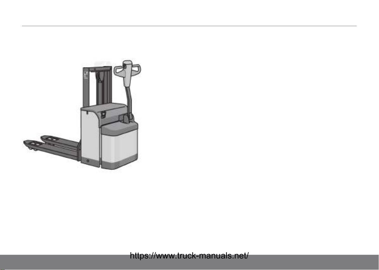
Powered trucks PLL, PLE, PSL, PSD, PS,
PSH .................................................................................................................... 14
PLL, PLE, PSL, PSD, PS, PSH driver
environment.................................................................................................. 15
PLP pedestrian truck .................................................................................... 16
PLP driver environment.............................................................................. 16
TS pedestrian truck ....................................................................................... 17
TS driver environment ................................................................................. 18
Trucks equipped with folding platform............................................. 20
Options.................................................................................................................... 21
08 BATTERY................................................................................................................. 22
Specifications..................................................................................................... 22
Battery changing.............................................................................................. 22
Maintaining and changing the battery.............................................. 25
Battery servicing .............................................................................................. 27
09 TRUCK COMPUTER (ATC)...................................................................... 28
Introduction.......................................................................................................... 28
General................................................................................................................... 28
Symbols and characters on the display.......................................... 28

TABLE OF CONTENTS
Display of battery status............................................................................. 29
Error messages ................................................................................................ 29
Change language............................................................................................ 29
Warnings................................................................................................................ 30
Menus...................................................................................................................... 31
Navigation in menus ..................................................................................... 31
10 DRIVING INSTRUCTIONS......................................................................... 33
Driving instructions PLL, PLE, PSL, PSD, PS, PSH,
PLP ..................................................................................................................... 33
Driving instructions TS ................................................................................ 36
11 GENERAL LOADING AND UNLOADING
INFORMATION.................................................................................................... 38
Responsibility for the load ........................................................................ 38
Responsibility for others............................................................................. 38
Maximal load ...................................................................................................... 38
Picking up a load ............................................................................................. 38
2-pallet handling............................................................................................... 38
12 GENERAL INFORMATION CONCERNING
STACKING.............................................................................................................. 39
Stacking.................................................................................................................. 39
13 MAINTENANCE OF THE TRUCK........................................................ 40
Daily maintenance (before each shift)............................................. 40
Daily Service (after each shift) .............................................................. 40
Weekly inspection .........................................................................................41
Preventive maintenance ............................................................................ 41
14 SERVICING AND MAINTENANCE ..................................................... 42
Service technician .......................................................................................... 42
Safety instructions for maintenance..................................................42
Maintenance intervals.................................................................................. 42
Maintenance instructions........................................................................... 55
15 SAFETY REGULATIONS............................................................................ 60
The authority and obligations of the truck
driver.................................................................................................................. 60
Getting in and out............................................................................................ 60
Driving the truck ............................................................................................... 60
Transportation security................................................................................ 64

TABLE OF CONTENTS
Lifting the forks.................................................................................................. 65
Normal operating conditions................................................................... 65
Exceptional operating conditions......................................................... 65
Work in hazardous environments ....................................................... 65
Parking.................................................................................................................... 65
When lifting the truck....................................................................................66
Assembling and putting into service ................................................. 68
Temporarily taking the truck out of service................................... 68
Taking the truck out of service............................................................... 69
Swinging loads.................................................................................................. 69
Installing the fire extinguisher ................................................................ 69
In the event of accidents............................................................................ 70
Noise/Sound levels........................................................................................ 70
Vibrations .............................................................................................................. 70
Climatic conditions ......................................................................................... 70
Work platforms.................................................................................................. 70
Overhead guard ............................................................................................... 70
Protective shoes .............................................................................................. 70
Lighting ................................................................................................................... 70
Additional units/Trailers .............................................................................. 70
Safety and warning signs.......................................................................... 71
16 DIMENSIONS ....................................................................................................... 75
Dimensions PL*/PS*..................................................................................... 75
Dimensions PS, PSH ................................................................................... 77
Dimensions PLP .............................................................................................. 79
Dimensions TS.................................................................................................. 80
17 WEIGHT.................................................................................................................... 82
Weight PLL, PLE, PSL, PSD, PS, PSH.......................................... 82
Weight PS, PSH............................................................................................... 82
Weight PLP.......................................................................................................... 82
Weight TS............................................................................................................. 82
18 ORDERING HANDBOOKS AND MANUALS.............................. 84
Ordering a Spare Parts Manual............................................................ 84

01INTRODUCTION
Instruction Handbook
This Instruction Handbook contains information that you, as
user of the truck, must be aware of in order to avoid/minimise
the risk of injury/damage to yourself or the truck. You are also
responsible to the company management, other people and
objects in your environment. You should therefore carefully read
all the way through this handbook before starting the truck for
the first time.
The Instruction manual describes a truck with standard
equipment, customer modifications may have been fitted.
It is not obvious that the options that are described in the
Instruction Handbook are suitable for all truck models. Contact
your truck supplier for information.
Our products are constantly being developed and renewed, we
therefore reserve the right to make alterations without prior
notice.
We have been manufacturing trucks since 1958. Quality,
operational safety and innovation have made us a leading
worldwide truck supplier.
Thank you for choosing us as your truck supplier.
Service
As the owner of one of our products, you are also welcome to
contact our service department.
We offer support and advice for any problems that may arise
and assistance with servicing and ordering of replacement
parts. Refer to the nearest authorised sales agent or service
workshop for assistance.
Genuine Parts
The reliability that we promise is contingent upon using our
original spare parts. Only our genuine replacement parts
guarantee correct operation, long life and the right to a
warranty.
Our truck driving courses
The importance of goods handling to companies and society in
general increases every year. At the same time, trucks are
being equipped with ever more advanced technical solutions. It
is therefore important that the operator, who has a key role to
play in goods handling, is given the correct conditions to
operate as safely and efficiently as possible. Statistics show
that the number of incidents decreases significantly when a
truck operator has been properly trained. To receive information
on current training offers, please contact your local authorised
representative, preferably, or, if necessary, another authorised
dealer.
Declaration of conformity
UniCarriers Europe AB, SE-435 82 Mölnlycke, Sweden,
guarantees under its own liability that the product delivered
meets relevant safety requirements in Directives 2006/42/EC
and 2004/108/EC. Risk analysis is based on ISO 3691 and EN
1726. The Declaration of conformity certificate accompanies
every machine, and it is important that it remains with the truck.
6

TRUCK MODIFICATION02
Truck modification
NOTE!
Unauthorized truck modification is not permitted.
No modifications or changes to powered industrial trucks that
can affect areas such as capacity, stability or safety
requirements for the truck may be made without advance
written authorisation from the manufacturer, its authorised
representatives or a successor to these. Contact your local
authorised dealer before any modification or change is made to
your industrial truck that may affect, for example, braking,
steering, visibility and connection of separate load aggregates.
Once permission has been granted by the manufacturer,
authorised representative thereof or successor to these, the
plate indicating the truck's capacity, decals, labels and
operating and instruction handbooks must also be changed
accordingly.
Only in the event that the manufacturer is no longer in business
and there is no successor to the company's stakeholders may
the user implement a modification or alteration to a powered
industrial truck. This applies on the condition that the user:
• arranges for the modification or alteration to be designed,
tested and implemented by one or more engineers who
are experts in industrial trucks and their safety
• maintains a permanent record of the design, test(s) and
implementation of the modification or alteration
• approves and makes appropriate changes to the capacity
plate(s), decals, tags and Instruction Handbook
• affixes a permanent and readily visible label to the truck
stating the manner in which the truck has been modified or
altered, together with the date of the modification or
alteration, and the name and address of the organization
which performed the task.
7

03ENVIRONMENTAL CONSIDERATIONS
We respect the environment
The majority of our products consist of steel, and can be
completely recycled.
Environmental impact
All products have an impact on the environment throughout
their entire life cycle.
The consumption of energy when in use is one of the most
important factors that influences the environment.
Through correct care, maintenance and use the consumption of
energy can be reduced, thereby reducing the environmental
impact.
Waste
Waste material in conjunction with repairs, maintenance,
cleaning, or scrapping, must be collected and disposed of in an
environment-friendly way and in accordance with the directives
of respective countries.
Such work should only be carried out in areas intended for this
purpose.
Recyclable material should be taken care of by specialised
authorities.
Environmentally hazardous waste, such as oil filters, hydraulic
oil, batteries and electronic equipment, can, if handled
incorrectly, have a negative effect on the environment and
human health.
8
THE SUPERVISOR04
Foreman’s responsibility
1. It is the responsibility of the supervisor, on behalf of the
company management, to ensure that the truck is driven
and used correctly.
2. The supervisor is responsible for compliance with the
requirements placed on the driver, refer to Driver
requirements page 10.
3. It is the duty of the supervisor to instruct and to ensure that
driver instructions are followed.
4. The supervisor must supply, and the truck operator must
sign for, the following relevant instruction handbooks.
The supervisor must also read and be familiar with the
appropriate instruction handbooks.
The fork lift truck must be insured with at least third party
insurance if this is a national authority requirement.
Maintenance personnel
NOTE!
Daily inspection and certain servicing shall be
carried out by the operator once he or she has
received sufficient training in the truck's construction
and care. Ongoing routine servicing should be
performed by an authorised service organisation. In
order to maintain effective and adequate servicing
for the truck, contact an authorised dealer, who can
offer a service agreement for routine inspection.
Conditions of use
The truck may be driven under the following conditions:
• indoors
• on a flat, hard and smooth surface
• with the maximum floor loading checked and not exceeded
• normal operating temperature, refer to Climatic conditions
page 70
• good visibility, adequate lighting and approved routes.
• driving with the load lowered
WARNING!
A truck operating in an area where there is a risk of
fire or explosion, or in any other high-risk area, must
be specially equipped for the purpose. The truck is
normally not equipped for these environments.
9

05TRUCK DRIVER
Authorization to drive a truck
The employer must ensure that the employee has the required
training and knows what must be observed in order to avoid
risks while working. The employer must take into consideration
an employee's suitability for the work in question. It is therefore
necessary that a person engaged as a driver completes the
appropriate truck driver training, both theoretical and practical,
that corresponds to the work assignments the driver is expected
to undertake after training. Further training may be required in
the event of major changes in work assignments. The employer
should give the employee written authorization to drive the truck
- as well as a written outline of the extent of his/her duties.
Driver requirements
The truck driver shall have the mental and physical capacity
required for the job. The driver shall also be aware of everything
that is relevant to the handling and manoeuvring of the truck,
traffic regulations and any other relevant instructions. The driver
shall have the permission of the supervisor to drive the type of
truck in question and be specially trained for the work and the
traffic conditions involved.
The responsibilities of the driver in specific markets
The following apply in respect of the driver's responsibilities
concerning the use of fork lift trucks:
• Australia: Users shall follow the requirements of AS
2359.2.
• North America: Users shall follow the requirements of the
applicable part of ANSI/ITSDF B56.
Inspection of the truck
• The driver of the truck is responsible to the supervisor, for
ensuring that the truck is kept in good working order.
• Daily maintenance shall be carried out carefully before the
start of each shift. See section Maintenance of the truck
page 40.
• Any faults must be reported to the supervisor immediately.
• The truck must be kept clean and maintained so that it is
always in good working order. It must be checked at
regular intervals in accordance with the service
instructions.
• Check that no safety equipment has been modified or put
out of service.
For optimum performance and so as not to invalidate the
warranty, use only genuine replacement parts!
10
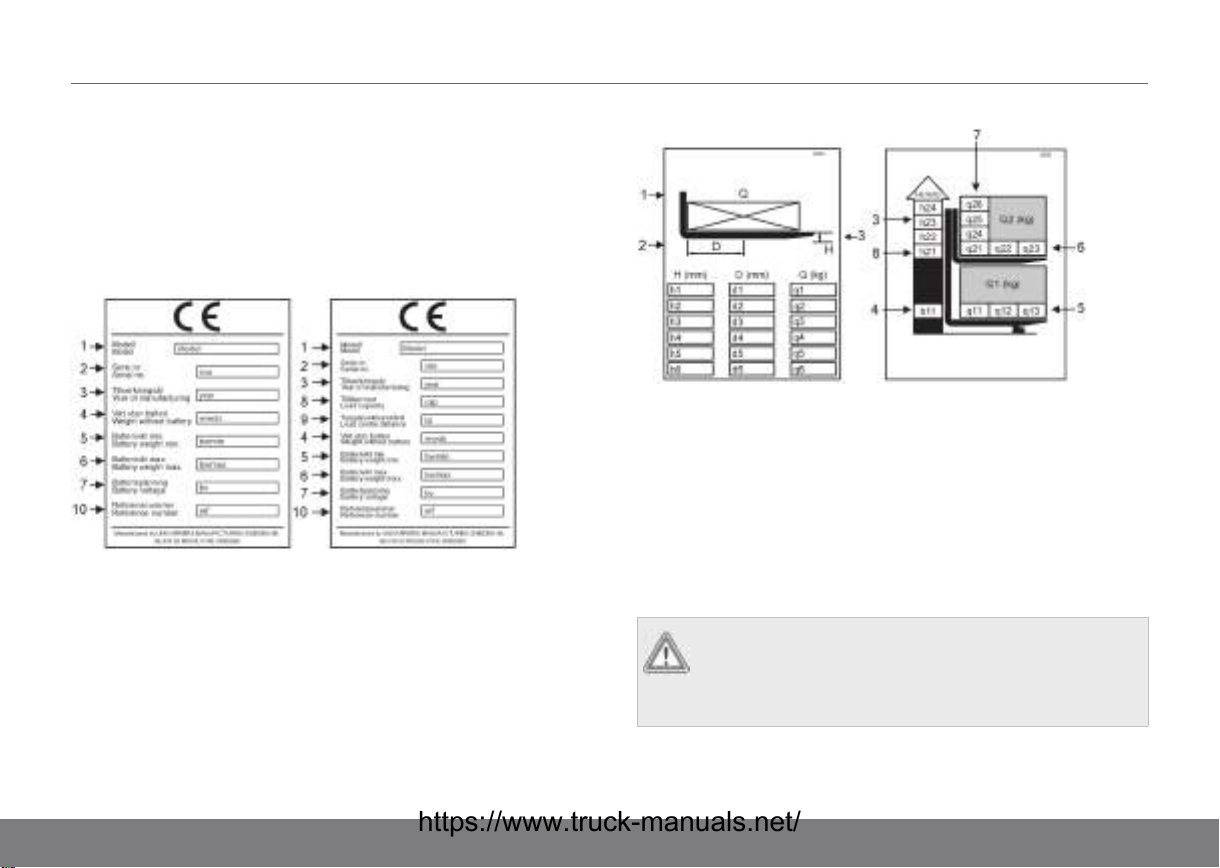
Explanation of machine plates
European machine plates
The Machine plate contains important information. Read it
carefully! The permitted load shall not be exceeded. The stated
load limit assumes that the load is evenly distributed on the
forks.
Figure 1. Machine plates
1. Model designation
2. Type Serial No./Version
(S=Special version)
3. Year of manufacture
4. Weight without battery
5. Minimum battery weight
6. Maximum battery weight
7. Battery voltage
8. Permitted load
9. Distance to centre of
gravity
10. Reference number (year and
nonth of manufacture)
Figure 2. Load limit plates
1. Actual capacity, Q
2. Load centre distance, D
3. Lift height for fork lift, H
4. Lift height for straddle lift
WARNING!
For the truck to fulfil stability requirements, the
instructions on the load limit plate must be
respected.
MACHINE PLATES06
5. Load limit for straddle lift,
Q1
6. Load limit for fork lift with load
on straddle lift, Q2
7. Load limit for fork lift without
load on straddle lift
8. Maximum lifting height for
fork lift with load on straddle
legs
11
06MACHINE PLATES
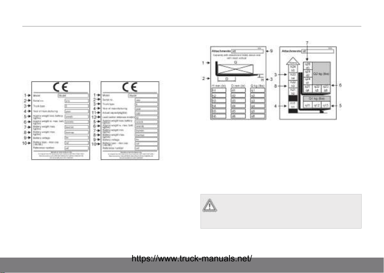
USA machine plates
The machine plate contains important information. Read it
carefully! Permitted loads may not be exceeded. The stated
load limit assumes that the load is evenly distributed over the
forks.
Figure 3. Machine plates
1. Model designation
2. Type Serial No./Version
(S=Special version)
3. Truck Type
4. Year of manufacture, week
and guarantee limit in
months
5. Weight without battery
6. Weight with battery
7. Minimum battery weight
8. Maximum battery weight
9. Battery voltage
10. Battery type maximum
capacity
11. Actual capacity, Q
12. Load centre distance, D
Figure 4. Load limit plates
1. Actual capacity, Q
2. Load centre distance, D
3. Lift height for fork lift, H
4. Lift height for straddle lift
5. Load limit for straddle lift,
Q1
WARNING!
To ensure the machine meets the stability
requirements always ensure the the lift capacity
shown on the machine plate is observed.
6. Load limit for fork lift with load
on straddle lift, Q2
7. Load limit for fork lift without
load on straddle lift
8. Maximum lifting height for
fork lift with load on straddle
legs
9. Serial number of the
attachment
12
MACHINE PLATES06
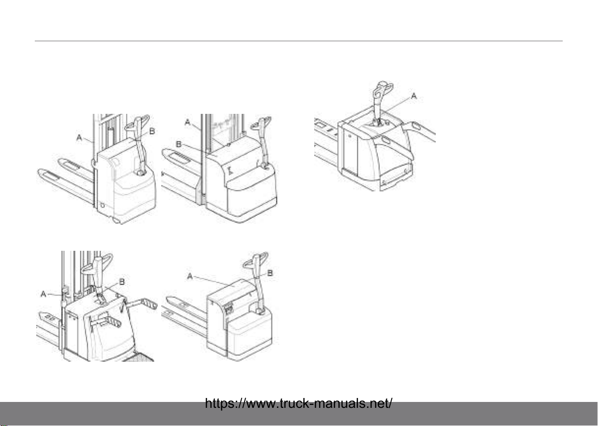
Location of machine plates
Location of machine plates
PSD, PSL PS, PSH
TS PLE
PLP
A. Machine plate
B. Load limit plate
13
07DESCRIPTION OF THE TRUCK
Powered trucks PLL, PLE, PSL, PSD, PS,
PSH
PL* is an electric truck for walking operators, specially adapted
for low level transportation, picking and handling at loading
bays. The truck can be equipped with a low mast for ergonomic
picking height or long forks for the transport of several load
carrier types. Usual loads are pallets or roller containers. The
trucks are intended for use indoors on hard level surfaces.
equipped with straddle lift for the transport of double load
carriers. Usual loads are pallets or roller containers.
PS* is an electric truck for walking operators, specially adapted
for stacking, short to medium distance internal transportation,
order picking and handling at loading bays. Certain trucks are
14
DESCRIPTION OF THE TRUCK07
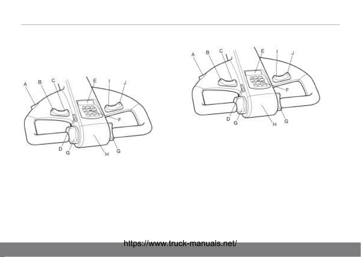
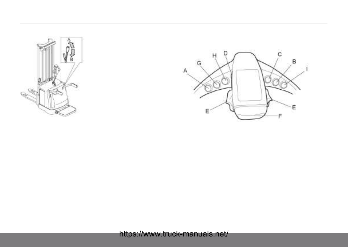
PLL, PLE, PSL, PSD, PS, PSH driver
environment
Functions
Controls PLL, PLE, PSL, PSD, PS
A. “Tiller up drive” driving at
slow speed with the tiller in its
end position (option)
B. Lower
C. Lift
D. Horn
E. Display
F. Keyboard (the keys may be
hidden by a cover)
G. Speed Controller
H. Belly safety switch
I. Lift vertically adjustable
straddle leg (option) (PSD,
PLE)
J. Lower vertically adjustable
straddle leg (option) (PSD,
PLE)
Controls PSH
A. “Tiller up drive” driving at
slow speed with the tiller in its
end position (option)
B. Lower vertically adjustable
straddle leg (option) (PSH)
C. Lift vertically adjustable
straddle leg (option) (PSH)
D. Horn
E. Display
F. Keyboard (the keys may be
hidden by a cover)
G. Speed Controller
H. Belly safety switch
I. Lift
J. Lower
Safety functions
The truck is equipped with a number of safety functions to
minimise the risk of accidents.
15

07DESCRIPTION OF THE TRUCK
• Automatic reversing if the driver becomes trapped between
the tiller arm and an obstacle (belly safety switch).
• Automatic stop when a fault occurs in the electrical
system.
PLP pedestrian truck
The PLP Presto is an electric low lifter for ride-on drivers,
specially adapted for transportation and handling at loading
bays. The truck can be equipped with a mast for stacking and
the transport of double load carriers, or with long forks for the
transport of several load carriers. Usual loads are pallets or
roller containers.
PLP driver environment
Functions
Controls
A. “Tiller up drive” driving at
slow speed with the lever in
its end position (option)
B. Lower
C. Lift
D. Horn
E. Display
F. Keyboard
G. Speed Controller
H. Belly safety switch
I. Forwards/backwards
adjustment (option)
16
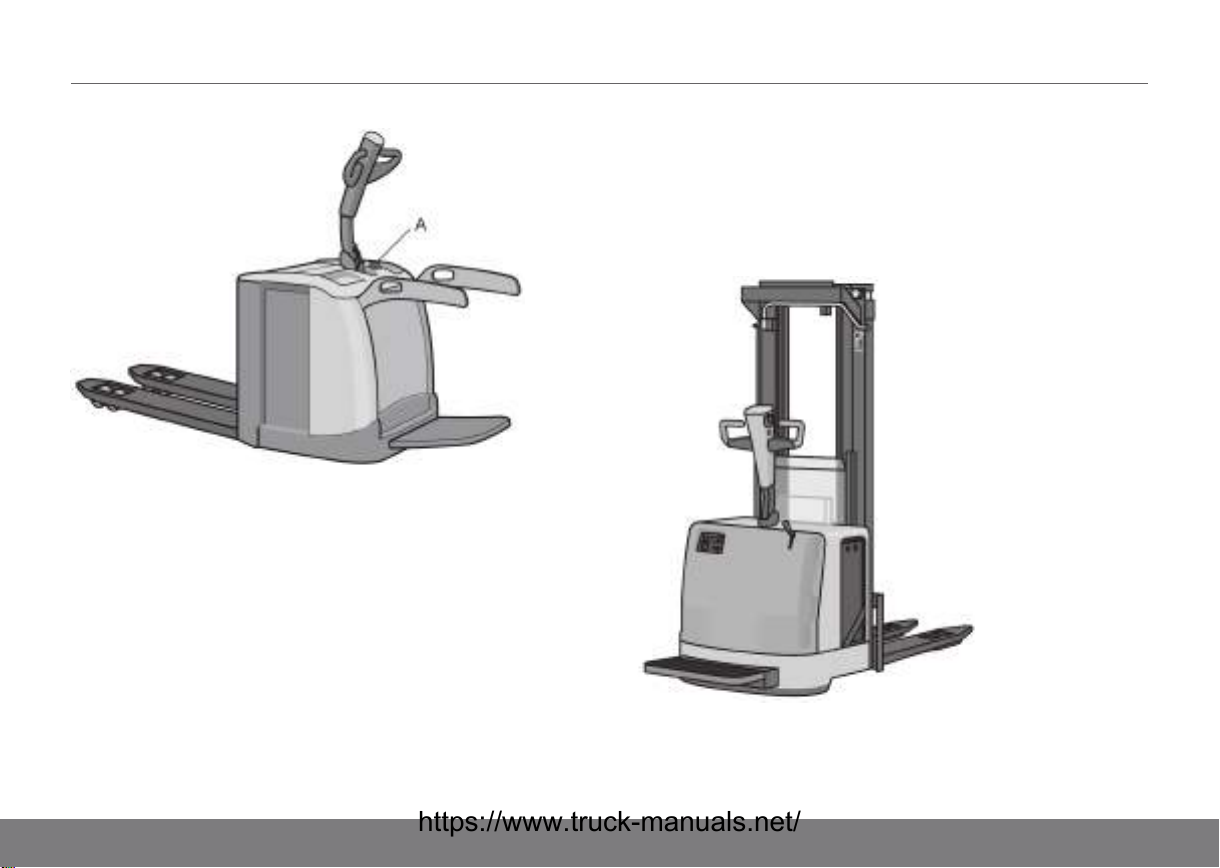
A. Emergency stop
Safety functions
The truck is equipped with a number of safety functions to
minimise the risk of accidents.
• Driving is prevented if the platform is down and there is no
operator standing on it.
• In the case of a fixed platform (option), lifting and lowering
of the forks are also prevented if there is no operator
standing on the platform.
DESCRIPTION OF THE TRUCK07
• Automatic reversing if the driver becomes trapped between
the tiller arm and an obstacle (belly safety switch).
• Automatic stop when a fault occurs in the electrical
system.
TS pedestrian truck
The TS is a versatile electric pedestrian stacker for a walking,
or, if the truck is equipped with a fold-up platform, a ride-on
operator. The truck is designed for stacking, internal
17
07DESCRIPTION OF THE TRUCK
transportation, and order picking. Certain trucks are equipped
with straddle lift for the transport of double load carriers,
ordinary pallets or handling at loading bays.
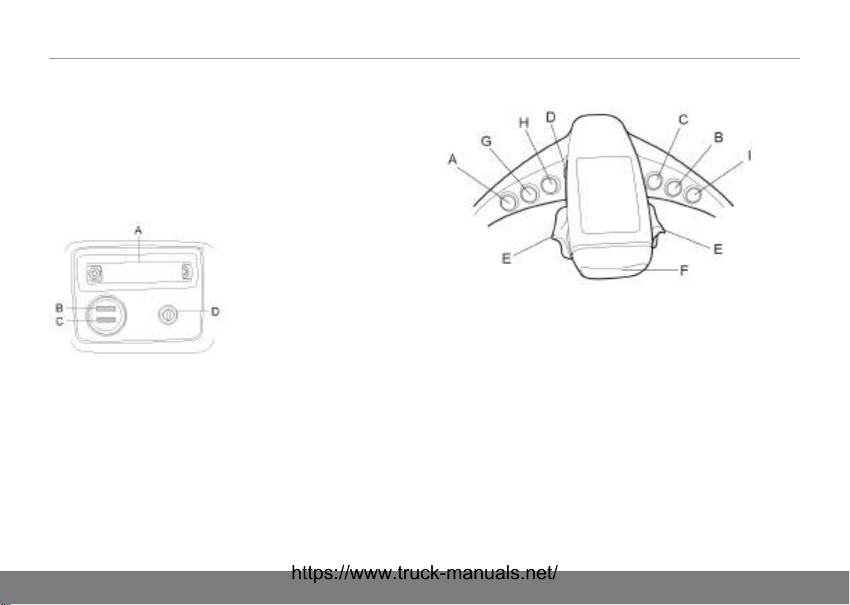
TS driver environment
Functions
Common controls
A. Battery plug (emergency
stop)
B. Battery indicator
C. Hour meter
D. Key switch
Controls for manual operation of lifting/lowering forks
A. Not used
B. Not used
C. Not used
D. Horn
E. Speed Controller
F. Belly safety switch
G. Lowering of the adjustable
height straddle legs (option),
otherwise not used
H. Lifting of the adjustable
height straddle legs (option),
otherwise not used
I. Not used
18
DESCRIPTION OF THE TRUCK07
Controls for proportional operation of lifting/lowering forks
(option)
A. Lower forks B. Lift forks
A. Not used
B. Lower
C. Lift
D. Horn
E. Speed Controller
Safety functions
The truck is equipped with a number of safety functions to
minimise the risk of accidents.
F. Belly safety switch
G. Lowering of the adjustable
height straddle legs (option),
otherwise the same function
as button B
H. Lifting of the adjustable
height straddle legs (option),
otherwise the same function
as button C
I. Not used
19
07DESCRIPTION OF THE TRUCK
• Driving is prevented if the platform is down and there is no
operator standing on it.
• Automatic reversing if the driver becomes trapped between
the tiller arm and an obstacle (belly safety switch).
• Lift stop at 1.8 m forks height and folded up gates. To
continue lifting, the gates must be folded down.
• Automatic stop when a fault occurs in the electrical
system.
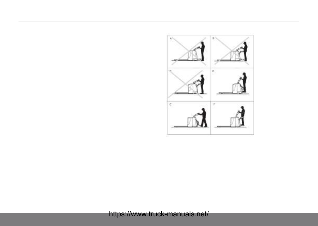
Trucks equipped with folding platform
If the machine is to be used as a pedestrian truck, the platform
must be folded up manually.
A number of safety functions have been built into the truck to
avoid accidents:
20
A. Platform folded down without
operator standing on it: The
truck cannot be driven.
B. Platform folded down and
gates up without operator
standing on it: The truck
cannot be driven.
C. Platform folded up and gates
up: The truck cannot be
driven.
D. Platform folded down with
operator standing on it and
gates down: The truck can be
driven at reduced speed.
E. Platform folded up and gates
down: The truck can be
driven at reduced speed.
F. Platform folded down with
operator standing on it and
gates up: The truck can be
driven at normal speed.
DESCRIPTION OF THE TRUCK07
Options
Additional equipment
The truck may be equipped with additional equipment. Among
other things, there are the following possibilities:
Table 1. PLL, PLE, PS, PSL, PSD, PSH
Additional equipment PLL PLE PS PSL PSD PSH
Writing desk
Earthing strap x x x x x
Rubber foot protection x x
Stretch film holder x
Pen holder x
AC/12 V DC converter x
Fire extinguisher x
Table 2. PLP, TS
Additional
equipment
Writing desk x
Earthing strap
Rubber foot
protection
Stretch film holder
PLP TS
Additional
equipment
Pen holder
AC/12 V DC
converter
Fire extinguisher
PLP TS
21
08BATTERY
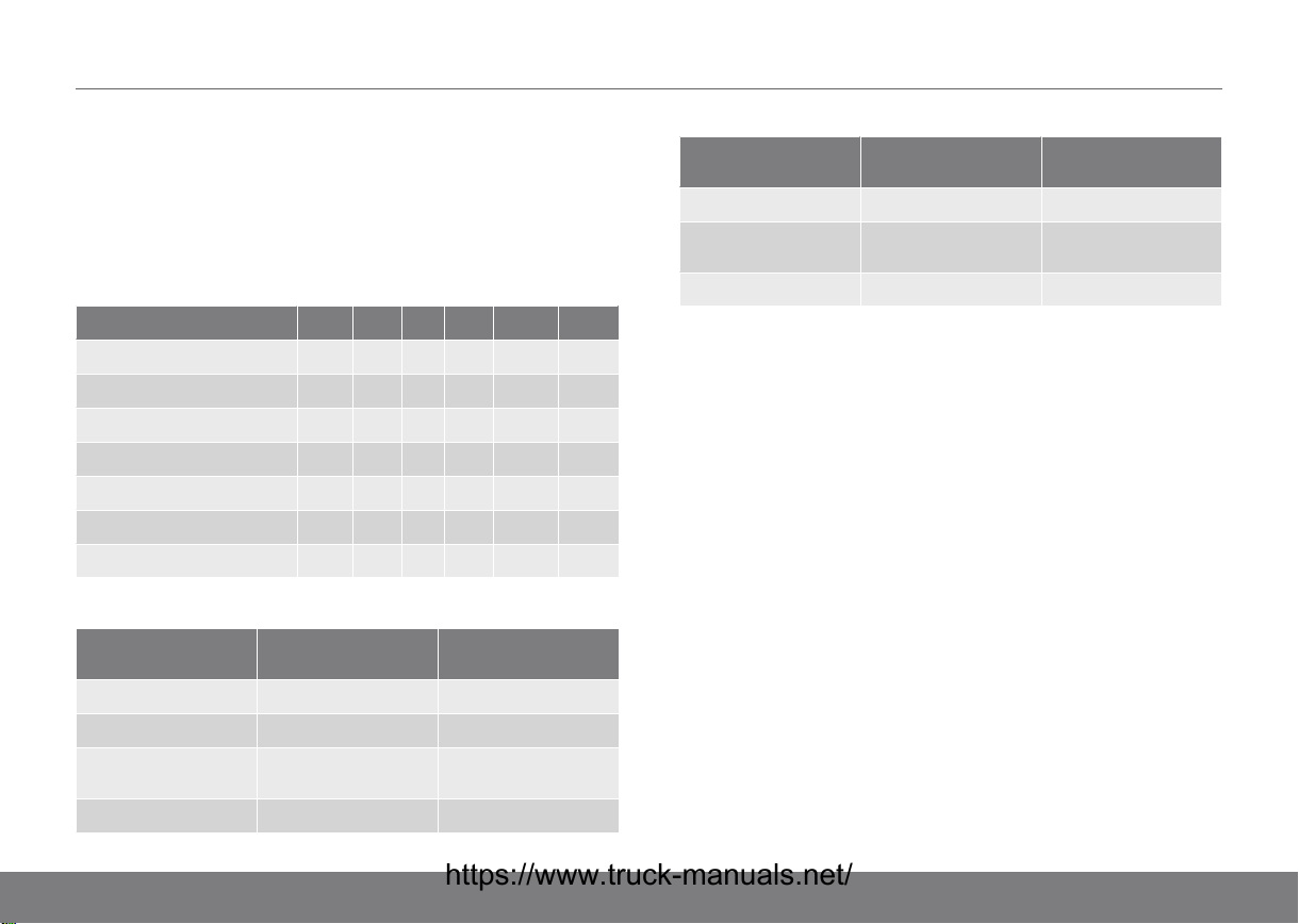
Specifications
Specifications PLL, PSD, PSL, PLE, PS, PSH
Table 3. Battery as standard
Truck model Battery voltage
and capacity
(V/Ah)
PLL 24/160-230 3,8-5,5 140/215
PLE 24/150 3,6 140/190
PSD/PSL/PS 24/160-230 3,8-5,5 140/215
PSH 24/240 5,8 240/300
PSH 24/345 6,5 330/360
Specifications PLP
Table 4. Battery as standard
Truck model Battery voltage
and capacity
(V/Ah)
PLP 200 24/220-400 5,3-9,6 250/370
PLP 250 24/330-600 7,9-14,4 350/500
Capacity
(kWh)
Capacity
(kWh)
Weight
min/max (kg)
Weight
min/max (kg)
Specifications TS
Table 5. Battery as standard
Truck model Battery voltage
and capacity
(V/Ah)
TS 24/240 5,8 215/290
TS 24/270 6,5 250/290
Capacity
(kWh)
Weight
min/max (kg)
Battery changing
Battery servicing may only be performed by specially trained
personnel. The battery may, however, be charged by other
personnel on the condition that a battery connector is used to
connect the battery to the charging unit. The battery is charged
in accordance with recommendations from the battery
manufacturer, using a charger adapted for the battery. The truck
is intended to be used with lead/acid batteries. Only fully
automatic charging systems should be used.
Follow local laws and safety regulations when charging the
battery. The area where batteries are charged should be
marked out and have proper ventilation. An eyewash station,
cleaning equipment, fire extinguisher and safety glasses must
be available.
WARNING!
Specific gravity checks should only be performed by
an authorised service technician.
22
WARNING!
Always use safety glasses. Acid can cause serious
corrosive injuries.
WARNING!
Explosive gas is generated during charging!
Smoking or a naked flame can cause an explosion!
WARNING!
Remove all rings, bracelets, necklaces and similar
items before handling batteries.
BATTERY08
23
08BATTERY
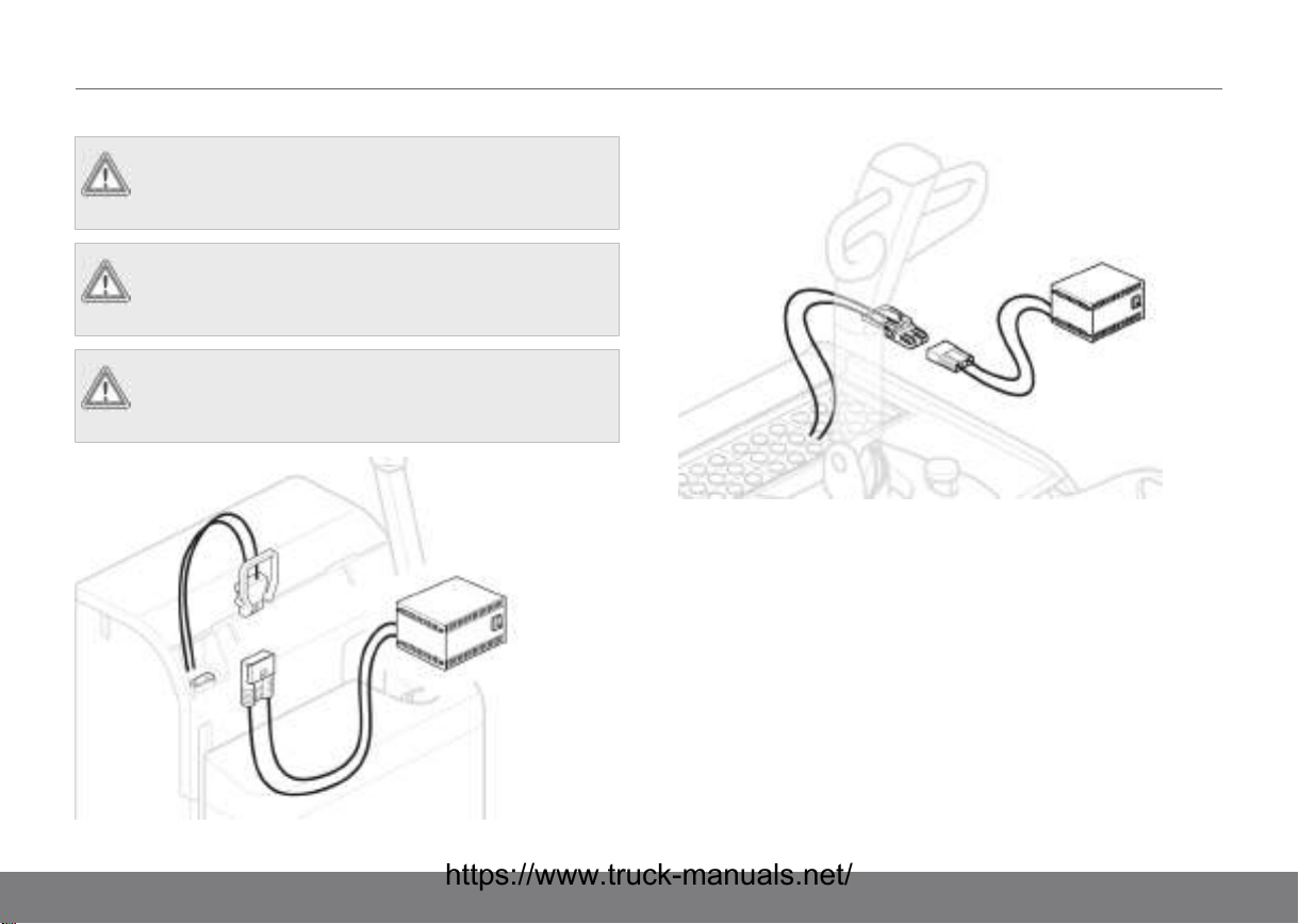
Before charging
1. Switch off the truck.
2. Remove any battery covers, to gain access to the battery
plug and to permit the heat generated during charging to
be ventilated away.
3. Remove the battery connector from the truck using the
battery charger handle. This procedure will vary depending
on truck model.
CAUTION!
Do not pull out the battery plug by pulling on its
cables.
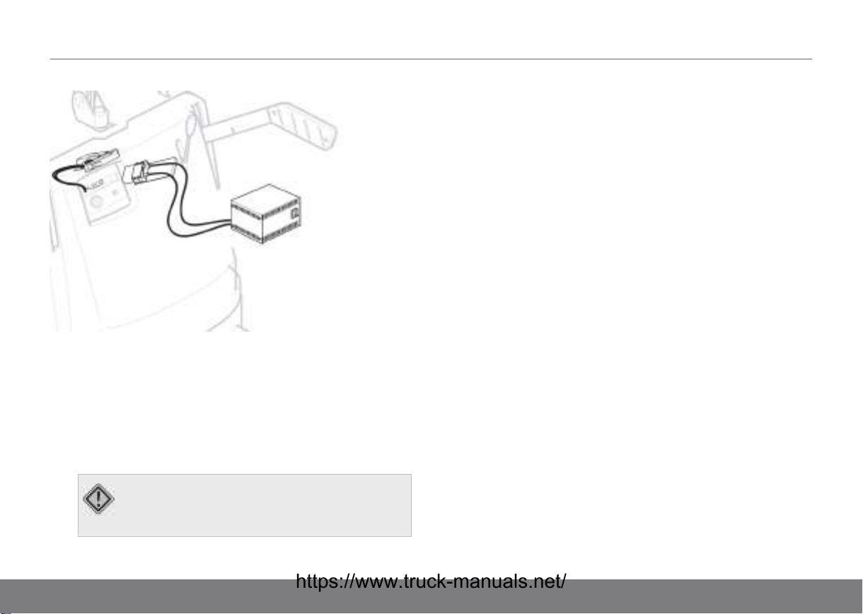
4. Check that the battery electrolyte level is not above or
below the cell plates.
The battery can be damaged if the cell plates become dry
during charging. There is a risk that the acid will spill over
during charging if the acid level is too high.
5. Connect the battery plug to the charger's connector.
6. Set the charging switch on the battery charger to on.
7. Check that the ammeter shows a normal indication.
After charging
1. Check that charging is completed.
2. Set the charging switch to off.
3. Disconnect the battery charger connector.
4. Top up to the correct level with distilled water.
5. Dry off the battery to prevent leakage current and self
discharging.
6. Connect the battery plug.
7. If there is a battery cover, close it.
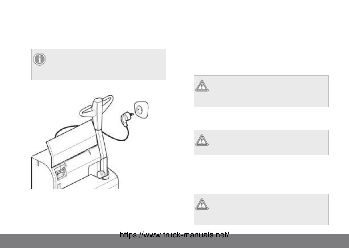
Charging with a built-in charger (option)
1. Switch off the truck.
2. Open the battery cover and pick up the mains power
connector.
3. Check that there is no visible damage to the cable or
connector.
24
BATTERY08
4. Plug the connector into a mains power outlet. Charging will
start.
NOTE!
For safety reasons the truck cannot be driven
while the mains power connector is connected
to an outlet.
When the battery is fully charged the LED lights green.
5. Pull the connector out of the mains power outlet.
6. Dry off the battery to prevent leakage current and self
discharging.
7. Return the mains power connected to the truck and closes
the battery cover.
Maintaining and changing the battery
Maintaining and changing the battery PL*/PS*, PS
1) Pull out the battery plug.
2) Open the battery cover.
WARNING!
There is a risk of crushing injury. Do not insert a
hand between the battery cover and the
chassis.
3) Attach the lifting device in the lifting eyes.
4) Lift the battery and set it to one side.
WARNING!
Observe care to avoid splashing waste acid or
oxide from the battery.
5) Perform a battery inspection in accordance with
Maintenance of the truck page 40.
6) Lift the battery in.
7) Carefully close the battery cover.
WARNING!
There is a risk of crushing injury. Do not insert a
hand between the battery cover and the
chassis.
25

08BATTERY
8) Connect the battery plug.
9) Check the battery voltage on the battery indicator.
Maintaining and changing the battery PSH
1)
Pull out the battery plug.
2) Open the battery cover.
3) Open the battery door using the battery key.
4) Roll out the battery on the battery carriage.
5) Perform a battery inspection in accordance with
Maintenance of the truck page 40.
6) Roll the battery back.
7) Close the battery cover.
8) Connect the battery plug.
9) Check the battery voltage on the battery indicator.
NOTE!
A battery carriage must be used when changing
battery.
WARNING!
Observe care to avoid splashing waste acid or
oxide from the battery.
Maintaining and changing the battery PLP
1)
Pull out the battery plug.
2) Release the battery lock.
3) Roll out the battery on the battery carriage.
4) Perform a battery inspection in accordance with
Maintenance of the truck page 40.
5) Roll in the battery after completed service.
6) Lock the battery in place with the battery lock and replace
the battery plug.
7) Check the battery voltage on the battery indicator.
NOTE!
A battery carriage must be used when changing
battery.
WARNING!
Observe care to avoid splashing waste acid or
oxide from the battery.
Maintaining and changing the battery TS
1) Pull out the battery plug.
2) Remove the battery locks (one on each side of the truck).
3) Roll the battery out to one side. Note that a safety stop is
activated when the battery has reached halfway out. When
26
BATTERY08
changing the battery on a truck with vertically adjustable
straddle legs, raise the straddle legs to their highest
position in order to remove the battery stop.
CAUTION!
There is a risk of pinching while rolling the
battery out or in.
NOTE!
A battery carriage must be used when changing
battery. Unscrew and remove the safety stop.
4) Perform a battery inspection in accordance with
Maintenance of the truck page 40.
5) Roll the battery in.
6) Refit the battery locks.
7) Refit the battery plug.
8) Check the battery voltage on the battery indicator.
Battery servicing
WARNING!
Battery and battery charger servicing may only be
carried out by specially trained personnel.
WARNING!
Avoid short circuits, which can cause explosion or
fire.
27

09TRUCK COMPUTER (ATC)
Introduction
The truck is equipped with an ATC system; a control and
monitoring system consisting of a display, a keyboard and a
control unit. The system is also equipped with a buzzer in order
to catch the driver’s attention in various situations.
NOTE!
Not available on TS trucks
General
In order to start the truck, the driver must enter Operator ID and
PIN code or use the keylock (option). Using the display, the
driver may find a lot of information after turning on the truck,
e.g.: date, time, battery status, as well as any error codes and
warnings. The Operator ID and PIN code are supplied along
with the delivery of the truck. The code should be changed after
delivery.
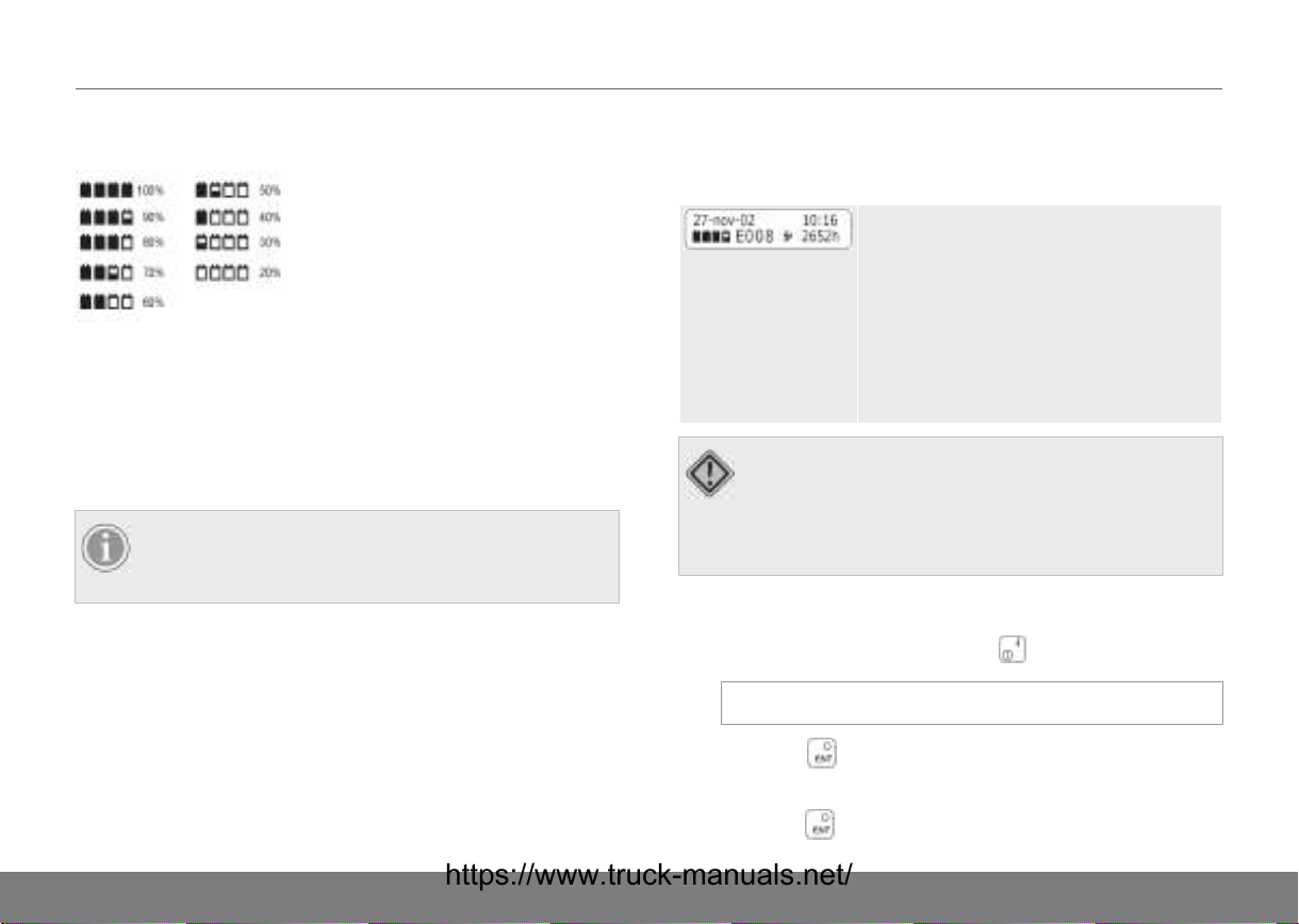
Symbols and characters on the display
A. Date: Day-month-year.
B. Time: Hours-minutes
C. Hour meter: Shows active
time or logon time. Normally,
total active time is
displayed.
D. Symbol normal speed/slow
speed: Shows whether the
truck is in normal speed or
crawler mode
(hare/tortoise).
E. Field for error codes: An error
code consisting of an
E+digits is shown if a fault
occurs (if a warning is
displayed, it covers the entire
upper row).
F. Battery indicator: Shows
battery status.
G. Symbol for lift stop. If the
truck is equipped with a
restart function, press push
button to continue
lifting.
28
TRUCK COMPUTER (ATC)09
Display of battery status
If the battery is discharged, the battery indicator will start
blinking and a buzzer will sound at regular intervals. If the
battery is not recharged or replaced, the lift function will shortly
be deactivated in order to avoid harming the battery or
preventing the truck from functioning normally. A deactivated lift
function is indicated by a lit ^ symbol to the left of the
hare/tortoise symbol.
NOTE!
When the battery status display indicates that the
battery is discharged, it must be recharged/replaced.
Error messages
Error codes
All error messages are shown on the bottom
row of the display. An error message is
presented in the form of a code, consisting of
the letter E and a code number, e.g. 008.
When an error code is shown, the truck will
go into a failsafe mode, which may mean that
the truck's functions will stop. Certain error
conditions are corrected automatically or by
turning the truck on and off. The error code
will then be turned off.
CAUTION!
The error code will persist in the event of a serious
error. If this occurs, an authorised service technician
should be contacted and given the error message
code.
Change language
1)
Navigate to “Settings”, using the button.
Settings
2)
Press the button.
3) Navigate with the arrow keys to select a language, then
press the button to confirm the selection.
29
09TRUCK COMPUTER (ATC)
SELECT LANGUAGE:
English
4) You will now enter the logon mode automatically with the
new language setting.
Operator ID:
?
Warnings
There are a number of different warnings used to catch the
driver’s attention in the case of, for example, an operational
error. Certain of the truck’s systems will also not be operable
until the driver has followed the command on the display.
•
Release throttle
The driver is asked to position the speed lever in neutral.
•
Release controls
The driver is asked to set all hydraulic levers to their
neutral positions.
•
Release tiller
The driver is instructed to place the steering arm to its
uppermost and lowermost positions.
disappear even though the driver has followed the instructions
on the display, contact and authorised service technician.
Other warning messages are shown if, for example. a system in
the truck is beginning to overheat. If the warnings do not
30
TRUCK COMPUTER (ATC)09
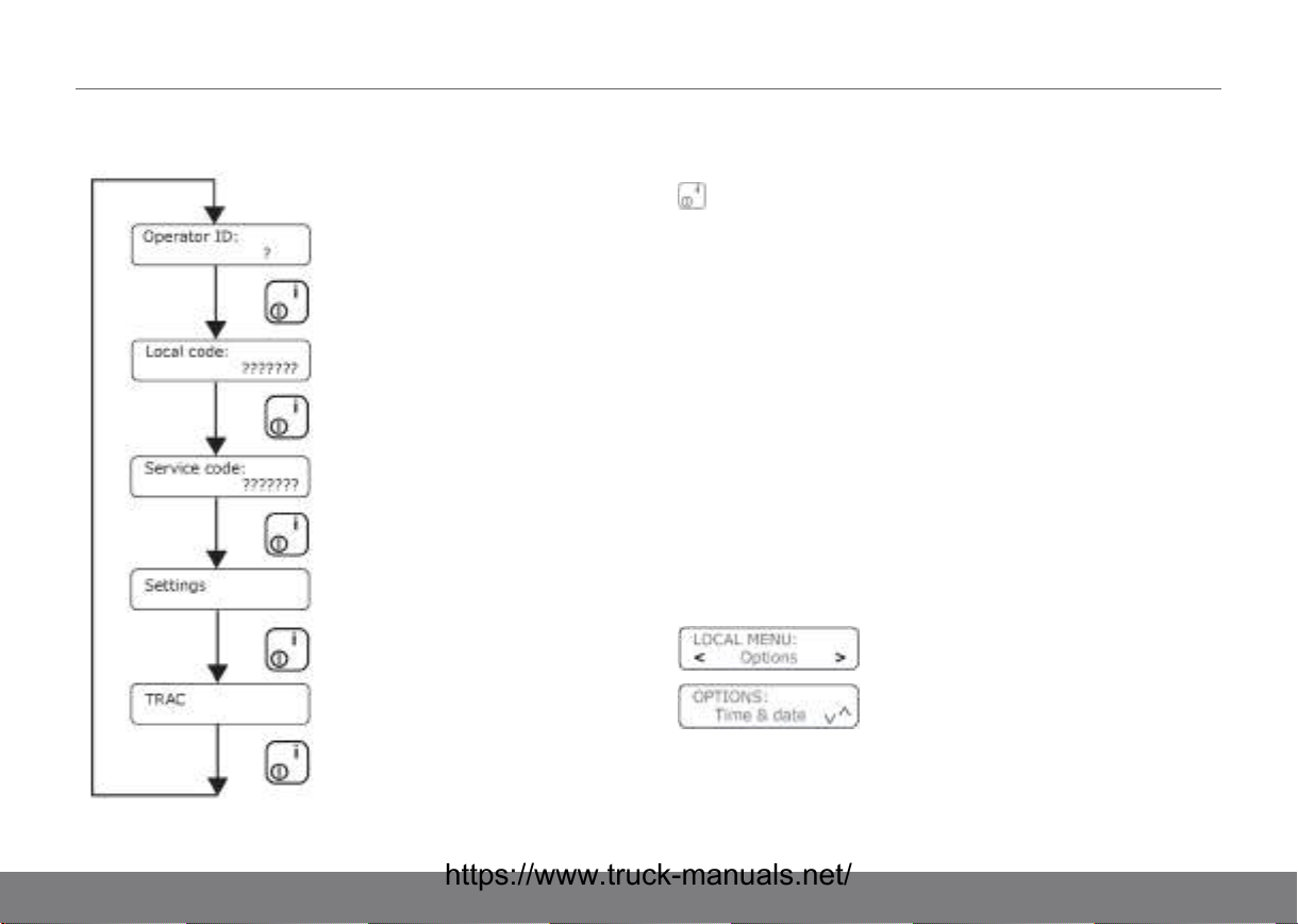
Menus
ATC has a number of functions available in a menu system.
There are five basic menus with multiple submenus. The button
is used to navigate between menus. Certain basic menus
require a password to be able to access them.
• Operator ID: Menu to start the truck.
• Local: Intended for local supervisor.
• Service: Intended for authorised service technician.
• Settings: Here, it is possible to set the language to be
shown in the display. ATC supports Swedish, English,
German and French. It is also possible to install one
additional language using special software.
• Trac: Intended for authorised service technician.
Navigation in menus
The arrow keys (buttons 4, 6, 2, 8 on the keyboard) are used for
navigating in the menus. You may navigate either vertically or
horizontally. The availability of these alternatives is shown on
the display.
31

09TRUCK COMPUTER (ATC)
•
To enter into a menu: Press the button.
•
To exit a selected menu: Press . The horn button
serves as an "Esc button". Press the button when
"Exit" is shown in the display.
32

DRIVING INSTRUCTIONS10
Driving instructions PLL, PLE, PSL, PSD,
PS, PSH, PLP
Starting the truck
1) Connect the battery plug and check that the emergency
stop function is disengaged.
2) If the truck is equipped with an electric lock, turn the key.
The display briefly shows a start image.
3) A request to state the operator identification will be
displayed. You will be asked to enter an Operator ID. Note
that there must be as many digits as question marks.
Operator ID:
?
4) Enter your PIN code.
Operator code
????
5) When the valid Operator ID and PIN code have been
entered, the truck will be ready to drive.
NOTE!
If a lever is activated when the truck is started,
you will see a message on the display asking
you to reposition the lever to neutral position.
Then the truck may be operated. This means
that sudden movements are avoided when
starting.
Driving instructions
1) Start the truck in accordance with Starting the truck page
33. Release the parking brake by moving the tiller arm
backwards-downwards (but not to the bottom position).
2) The truck begins to move when the tiller arm speed control
is pushed forwards/backwards. The further the speed
control is moved the faster the truck will move.
3) There are several ways to brake the truck:
• Brake the truck by reversing, i.e. changing the
direction of travel.
NOTE!
The further the speed control is moved the
greater the braking capacity.
33

10DRIVING INSTRUCTIONS
• Brake by moving the speed control back to its neutral
position and moving the tiller arm up or down to its
end position.
NOTE!
The brakes function whether the lever is
released or not.
4) If the main power needs to be disconnected in an
emergency, press the emergency stop button or pull out
the battery plug. The emergency stop buttons are on the
left and right hand sides of the driver cab facing the forks.
5) In order to avoid crushing injuries during driving, there is a
belly switch at the end of the tiller arm. When the belly
switch (H) is pressed in, the truck will move in the direction
the forks are pointing.
6) It is possible to manually activate crawl speed during
operations. Select crawl speed by pressing the button
(F). (Button (F) to go directly to normal speed.)
7) Switch off the truck in accordance with Switching off the
truck page 34.
Switching off the truck
1)
To turn off the truck: Keep the button pressed in for
approx. two seconds. The display will show “shutting
down” and then show the log-on text.
shutting down...
Operator ID:
?
NOTE!
Always turn off the truck in accordance with the
above instructions before the battery plug is
disconnected to avoid locking the program or
damaging the ATC system.
2) In the case of a lengthy stop, pull out the battery plug.
NOTE!
Emergency stop shall not be used to turn off the
truck.
Normal or crawler mode
Normal speed mode
A symbol for normal speed (hare) or crawler (tortoise) is always
shown on the display, depending on which is currently active.
34

DRIVING INSTRUCTIONS10
Crawler mode
It is possible to manually activate crawl speed during
operations. Button alternates between the two speed
selections. (Button to go directly to normal speed.) Various
safety systems in the truck may automatically reduce the speed
in certain situations. For example, driving with forks lifted high
and/or folded out side stabilizers results in reduced speed. The
symbols for normal speed or crawler mode are not changed by
reducing the speed.
Standby position
Standby mode is only used for shorter stops during the work
shift. At the end of the work shift or when the truck is going to
be left unattended, it should always be turned off.
1)
To enter standby mode: Keep the button pressed until
the text “standing by” is shown on the display.
2)
To return to operating mode: Briefly press the button
again.
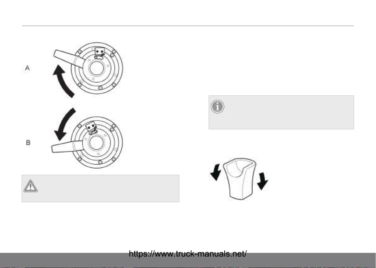
Manual release of the brake PLL, PSD, PLE, PSL, PS
The brake can be released in order to move a truck without
power by turning the handle at the top of the brake clockwise
(A). The truck cannot be driven in this position. To return to
normal operation, turn the handle anticlockwise back to normal
position (B).
35
10DRIVING INSTRUCTIONS
WARNING!
The brake may only be released when the truck is
standing still on clean, level and solid ground.
2) Turn the key.
Driving instructions
1) Start the truck in accordance with Starting the truck page
36.
2) Release the parking brake by moving the tiller arm
downwards (but not to the bottom position).
NOTE!
For trucks with fixed/protected platforms, the
driver must stand on the platform to be able to
use any of the hydraulic functions.
3) The truck begins to move when the lever on the operating
handle is pushed forwards/backwards. The further the
speed control is moved the faster the truck will move.
Driving instructions TS
Starting the truck
1) Connect the battery plug.
36
4) There are several ways to brake the truck:
• Brake the truck by reversing, i.e. changing the
direction of travel.

DRIVING INSTRUCTIONS10
NOTE!
The further the speed controller is moved the
greater the braking capacity.
• Brake by moving the lever on the operating handle
back to its neutral position and moving the operating
handle up or down to its end position.
NOTE!
The brakes function whether the speed control
is released or not.
5) If the main power needs to be disconnected in an
emergency, pull out the battery plug.
6) In order to avoid crushing injuries during driving, there is a
belly switch at the end of the tiller arm. When the belly
switch is pressed in, the truck will move in the direction the
forks are pointing.
7) Switch off the truck in accordance with Switching off the
truck page 37.
Switching off the truck
1) Switch off the truck by turning the key counterclockwise.
2) In the case of a lengthy stop, pull out the battery plug.
NOTE!
Emergency stop shall not be used to turn off the
truck.
37

11GENERAL LOADING AND UNLOADING INFORMATION
Responsibility for the load
The driver of the truck is responsible for the load that is being
carried during transport. There must not be any risk of the load
tipping or sliding off during transport. The driver of the truck has
the right and duty to refuse to carry any load that is a clear
safety hazard. Refer to the load limit plate to see the permitted
maximum load for the truck.
Responsibility for others
Operate the truck so that there is no risk of an accident. No one
may pass or stand under the raised forks, whether they are
carrying a load or not. The driver has the right and duty to see
that these directives are followed.
Maximal load
The maximum lifting capacity of the truck must not be exceeded
(refer to the fork lift truck load limit plate). Note the effect of the
centre of gravity on the lifting capacity.
Picking up a load
Always pick up a load so that it comes to rest as close to the
mast as possible.
CAUTION!
Check the location of the centre of gravity of the
load.
CAUTION!
Do not drive with the load lifted, except during
2-pallet handling.
2-pallet handling
The following applies to trucks with adjustable outriggers which
make 2 pallet handling possible:
• Adjust the speed in accordance with floor conditions, load
distribution and when cornering.
• Remember that a higher centre of gravity makes the truck
less stable. Try to have the load as low as possible, with
the heaviest load always lowermost.
• Whilst loading with only the forks, the straddle legs must
be completely lowered.
• Refer to the load limit plate to see the permitted load
combinations for a particular truck.
38

GENERAL INFORMATION CONCERNING STACKING12
Stacking
1) Approach the stack with the load in the lowered position.
2) Lift the load sufficiently high that it clears the stack or shelf
and then drive towards the stack.
3) When the load is in a suitable position, lower it onto the
stack.
4) Lower the forks so that they release the load/pallet, and
check that no-one is behind the truck before reversing
away from the stack.
5) Lower the forks into their transport positions.
6) When fetching a load from a stack, carry out these
movements in reverse order.
39

13MAINTENANCE OF THE TRUCK
Daily maintenance (before each shift)
Responsibility: Fork lift truck driver
CAUTION!
Naked flames or smoking are prohibited when
working on or near to the battery.
CAUTION!
Loading ergonomics must be observed during
battery change or battery check.
1) Check that the battery cables, connections and plugs are
connected correctly and not damaged.
2) Check that the battery is properly secured in its
compartment.
3) Check that the truck is not leaking oil.
4) Check the horn by activating the controls while the truck is
running.
5) Check the braking capacity on the main brake and parking
brake.
6) Check for external damage or excessive wear on the
wheels.
7) Check that there are no error messages or warnings on
the truck computer display.
8) Check that the securing arrangements for the finger
protection are intact and that there is a good view through
the protection.
WARNING!
There is the danger of personal injury if the
truck is operated without having the finger
protection in place.
WARNING!
There is a danger to life if the truck is driven
with insufficient visibility through the finger
protection.
CAUTION!
Errors detected during daily inspection must be
reported to a foreman/supervisor. See section
Truck Driver page 10.
9) Check the height measuring system reflector surface.
10) Trucks with gates: check the gate switches.
Daily Service (after each shift)
Responsibility: Fork lift truck driver
40

MAINTENANCE OF THE TRUCK13
Battery changing
1. Check the battery voltage on the battery indicator.
2. Charge the battery as necessary. The battery is charged in
accordance with the recommendation from the battery
manufacturer. Only fully automatic charging units should
be used.
Refer to Battery changing page 22 for the charging
procedure.
If there is damage
Any damage that has occurred must be reported to the
supervisor.
Weekly inspection
Responsibility: Truck operator
1) Clean the battery; see the battery manufacturer's
maintenance instructions.
2) Check the oil level in the hydraulic system by pushing all
the hydraulic cylinders to their fully extended positions.
Then, check that the fork truck raise all the way up to
maximum lift height without the pump sucking air.
3) Check that the wheels have not separated – tread/hub and
tread/cord.
4) The outside of the truck must be cleaned. Vacuum clean
and wipe with moist cloth in the operator cab. Electrical
panels and circuit boards must always be protected from
fluids. Damage to the truck caused by fluids in electrical
components is not covered by the manufacturer's warranty.
Preventive maintenance
NOTE!
Preventive maintenance must be carried out by
specially appointed and trained personnel with a
good working knowledge of the function and
maintenance of the truck.
To obtain the best results from your truck investment, we advise
you to contact an authorised service technician and take out a
service agreement for preventive maintenance.
41
14SERVICING AND MAINTENANCE
Service technician
NOTE!
Servicing and maintenance must be carried out by a
specially appointed and trained technician with a
good working knowledge of the truck's function and
maintenance.
To obtain the best results from your truck investment, we advise
you to contact an authorised service technician and take out a
service agreement for routine maintenance.
Safety instructions for maintenance
Working at height
Comply with local safety instructions when working at height.
Precautionary measures during repair
Extreme importance must be placed on precautionary
measures to avoid accidents during all work on the truck.
•
• Ensure that the drive wheel is off the ground before trouble
shooting. Secure the truck with blocks.
WARNING!
The battery plug should be pulled out before
working on the truck.
• To prevent injuries caused by crushing the battery plug
should always be removed when working on and around
the mast and hydraulic unit.
• When dismantling parts of the hydraulic system the system
must not be pressurised, e.g. the pump motor is shut off
and the forks are down.
• The battery should always be protected during grinding
work.
• When changing a fuse the controllers must be thoroughly
discharged. (Remove the battery plug and wait for two
minutes before fuses are changed, otherwise there a risk
of arcing.)
• Great caution must be observed when removing gas
springs.
Maintenance intervals
Recommended replacements
NOTE!
To ensure correct operation, use only original spare
parts.
42

SERVICING AND MAINTENANCE14
• The hydraulic oil filter and air filter for the hydraulic oil tank
must be changed after every 500 hours of operation. For
TS, this should happen every 1,000 hours of operation.
NOTE!
Only TS trucks have replaceable hydraulic
filters.
• The hydraulic oil must be changed annually or every 1,000
hours of operation.
CAUTION!
If the hydraulic oil has been heated to over
60°C the oil and the filter must be replaced
immediately, since the technical properties of
the oil may have changed.
• Hoses should be replaced after 5 years, since they are
perishable.
Servicing, type and frequency
General
A complete operations test must be performed before the
inspection. Faulty functions must be rectified before the
inspection.
First service (200 hours)
This service has the purpose of securing the operation of the
truck and its component parts. The gearbox oil and hydraulic oil
filter must be changed and a functional test carried out in
accordance with the following list.
• Check for external damage on chassis.
• Check of weld joints at vital points.
• Check of lifting devices.
• Check of component attachments.
• Functional test, lever, lever bolts, 195 Nm.
• Check of the horn.
• Test drive backwards and forwards, and turning.
• Check of the drive unit.
• Check of all the wheels.
• Test of the brake function.
• Change the oils and filter in accordance with instructions.
• Check for oil leakage.
• Check of the hydraulic unit, pipes and hoses.
• Check of the cylinders.
• Function test, lifting and lowering.
• Lubrication in accordance with lubrication chart.
• Measurement and check of the battery and charging
function.
Service intervals
Service must be carried out regularly, once a year or after 500
hours of operation with normal use of the truck. The planned
43

14SERVICING AND MAINTENANCE
servicing includes operations such as test driving, functional
tests, and the changing of filters and oils, etc.
NOTE!
In the case of demanding and/or dusty environments
with humid or corrosive air, it is advisable to perform
maintenance more often. Reduce the periods
between maintenance by one half (or one third).
Service points PLP, PS, PSH, TS
Planned service inspections are implemented in accordance
with the following points:
X Obligatory
O Not obligatory
Chassis
Descriptions PLP PS/PSH TS
Signs/Decals X X
Covers and panels X X X
Overhead guard X
Rail wheel X X O
Battery stop, Lock, Rollers X X X
Rubber mat X X
Chassis X X X
Chassis
Descriptions PLP PS/PSH TS
Lubrication X X X
Link system X X O
Stabilizers X O
Castor wheel X X X
Microswitch X X X
Pivot points X
Driver’s platform X X
Gates X X
Colour X X X
Finger protection X X
Machine plate X X X
Drive unit
Descriptions PLP PS/PSH TS
Gearbox X X X
Traction motor X X X
Drive wheel X X X
Drive shaft X X X
Gearbox oil level X X X
44

SERVICING AND MAINTENANCE14
Mast system
Descriptions PLP PS/PSH TS
Lift chains X X X
Forks, fork carriage X X X
Bearings/Rollers X X X
Lubrication X X X
Mast profile X X X
Pull rods X X O
Steering
Descriptions PLP PS/PSH TS
Servo motor X O
Steering servo unit X O
Sliding bearing X X
Tiller foot X X X
Steering Bearing X X
Steering belt/Steering chain X X
Hydraulic system
Descriptions PLP PS/PSH TS
Hydraulic oil level X X X
Hoses X X X
Hydraulic system
Descriptions PLP PS/PSH TS
Couplings X X X
Pump motor X X X
Hydraulic pump X X X
On/off valve proportional
valve
Friction force system X
Descriptions PLP PS/PSH TS
Cylinders X X X
Electrical system
Descriptions PLP PS/PSH TS
Cables, Switches X X X
Contactors X X X
Battery X X X
Traction motor controllers X X X
Horn X X X
Speed Controller X X X
Mast sensor/switch X X
X X X
Lift cylinders
45

14SERVICING AND MAINTENANCE
Electrical system
Descriptions PLP PS/PSH TS
Fuses X X X
Battery plug X X X
Cooling fan X X
Truck computer X X
Belly switch button X X X
Emergency stop X X X
Lift switch X
Hour meter X X X
Driver presence sensor X X
Battery indicator X X X
Key switch O O X
Brake-System
Descriptions PLP PS/PSH TS
Brake function X X X
Parking brake X X X
Brake disc X X X
Service points PLL, PLE, PSD, PSL
Planned service inspections are implemented in accordance
with the following points:
X Obligatory
X Not obligatory
Chassis
Descriptions PLL PLE PSD/PSL
Signs/Decals X X X
Covers and panels X X X
Rail wheel X X X
Battery stop, Lock, Rollers O O O
Chassis X X X
Lubrication X X X
Link system X X X
Stabilizers X
Castor wheel X X X
Microswitch X X X
Colour X X X
Finger protection X
Machine plate X X X
46

SERVICING AND MAINTENANCE14
Drive unit
Descriptions PLL PLE PSD/PSL
Gearbox X X X
Traction motor X X X
Drive wheel X X X
Drive shaft X X X
Gearbox oil level X X X
Mast system
Descriptions PLL PLE PSD/PSL
Lift chains X X
Forks, fork carriage X X X
Bearings/Rollers X X X
Lubrication X X X
Mast profile X X
Pull rods X X X
Steering
Descriptions PLL PLE PSD/PSL
Sliding bearing X X X
Tiller foot X X X
Steering Bearing X X X
Hydraulic system
Descriptions PLL PLE PSD/PSL
Hydraulic oil level X X X
Hoses X X X
Couplings X X X
Pump motor X X X
Hydraulic pump X X X
On/off valve proportional
valve
Descriptions PLL PLE PSD/PSL
Cylinders X X X
Electrical system
Descriptions PLL PLE PSD/PSL
Cables, Switches X X X
Contactors X X X
Battery X X X
Traction motor controllers X X X
Horn X X X
Speed Controller X X X
X X X
Lift cylinders
47

14SERVICING AND MAINTENANCE
Electrical system
Descriptions PLL PLE PSD/PSL
Fuses X X X
Battery plug X X X
Truck computer X X X
Belly switch button X X X
Emergency stop X X X
Hour meter X X X
Battery indicator X X X
Key switch O O O
Brake-System
Descriptions PLL PLE PSD/PSL
Brake function X X X
Parking brake X X X
Brake disc X X X
Consumable materials
Only supplies (oils, grease, lubricants etc.) that have been
approved by our genuine spare parts department may be used
for servicing and maintenance of the truck. See Genuine Parts.
Lubrication chart PL*/PS*
Figure 5. PSL, PSD
1. 500 hr service 2. Annual service
48

SERVICING AND MAINTENANCE14
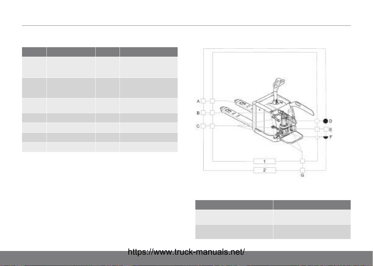
PL*/PS* components requiring lubrication
Location Explanation
A1 Mast profile roller surfaces and slide surfaces
A2 Thrust rollers
B Lift chains
C Straddle legs
D Fork carriage
E Bogie wheel
F Battery rollers
G Castor wheel - sliding bearing, grease nipple
H Speed and brake controls - slide surfaces and springs
I Steering arm - gas spring
J Steering arm housing
K Hydraulic tank
L Guide ring
M Gearbox
Figure 6. PLE, PLL
1. 500 hr service 2. Annual service
49

14SERVICING AND MAINTENANCE
Lubrication chart PS/PSH
Figure 7. PS
1. 500 hr service 2. Annual service
50
Figure 8. PSH
1. 500 hr service 2. Annual service
SERVICING AND MAINTENANCE14
PS/PSH components requiring lubrication
Location Explanation Location Explanation
A1 Mast profile roller
surfaces and slide
surfaces
A2 Thrust rollers H Speed and brake
B Lift chains I Steering arm - gas
C Straddle legs J Steering arm housing
D Fork carriage K Hydraulic tank
E Bogie wheel L Guide ring
F Battery rollers M Gearbox
G Castor wheel - sliding
bearing, grease nipple
controls - slide surfaces
and springs
spring
Lubrication chart PLP
1. 500 hr service 2. Annual service
Components to lubricate, PLP
Location Explanation
A Mast section - roller surfaces and
slide surfaces
B Gates – bearing surfaces
lubricated
51

14SERVICING AND MAINTENANCE
Location Explanation
C Spring-mounted drive unit – link
bearings, 12 grease nipples
D Hydraulic oil
E Castor wheel - sliding bearings, 2
grease nipples
F Gearbox oil
G Platform, 2 grease nipples
Lubrication chart PLP CD
1. 500 hr service 2. Annual service
52
SERVICING AND MAINTENANCE14
PLP CD components requiring lubrication
Location Explanation
A Thrust rollers
B Mast profile roller surfaces and
slide surfaces
C Bogie wheel
D Gates, bearing surfaces
E Fork carriage
F Spring-mounted drive unit, link
bearings, 12 grease nipples
G Lift chains
H Hydraulic oil
I Castor wheel, sliding bearings, 2
grease nipples
J Gearbox oil
K Platform, 2 grease nipples
Lubrication chart TS
1. 500 hr service 2. Annual service
53

14SERVICING AND MAINTENANCE
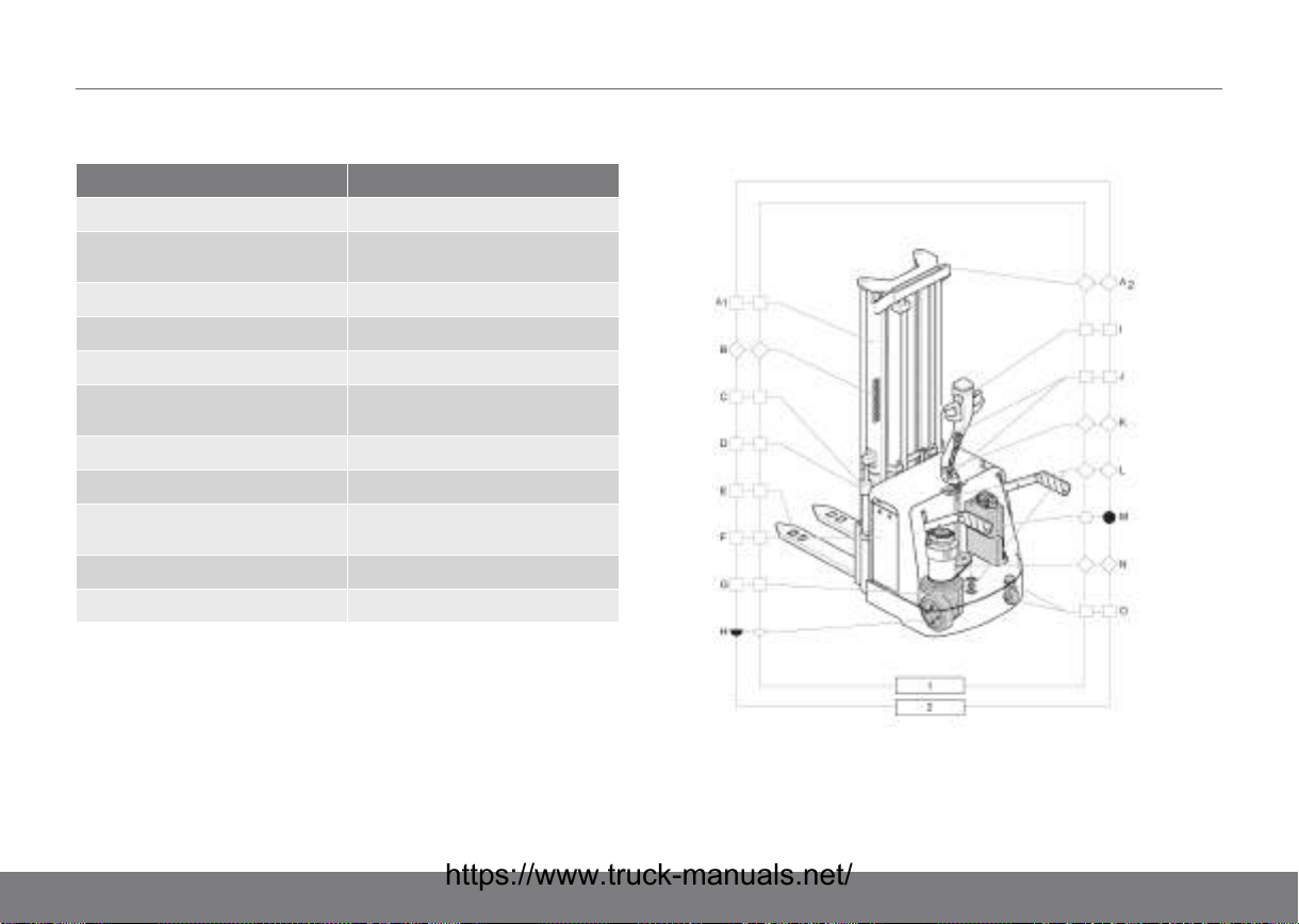
TS components requiring lubrication
Location Explanation
A1 Mast section - roller surfaces and slide surfaces
A2 Thrust rollers - all
B Lift chains - all
C Fork carriage - support rollers
D Fork carriage – slide surfaces
E Bogie – axle (unloaded)
F Battery rollers
G Guide ring
H Gearbox
I Speed and brake controls – slide surfaces and springs
lubricated
J Attachment gas spring steering arm
K Steering arm housing
L Upper/lower guide bearings lubricated
M Hydraulic tank
N Steering chain
O Castor wheel, sliding bearings, wheel bearings
Symbol key lubrication chart
Symbol Explanation Symbol Explanation
Oil filter and air filter,
change
Gearbox oil, check Gearbox oil, change
Grease Only cold store
Chain spray Chain spray/oil
Hydraulic oil, oil filter
and air filter, change
version
Applicable in general for the symbols:
Unfilled symbol, check lubrication.
Filled symbol – Change.
Fuses
General
WARNING!
Fuses should be changed by an authorised service
technician.
WARNING!
Always switch off the current by pulling out the
battery plug when changing fuses.
54

SERVICING AND MAINTENANCE14
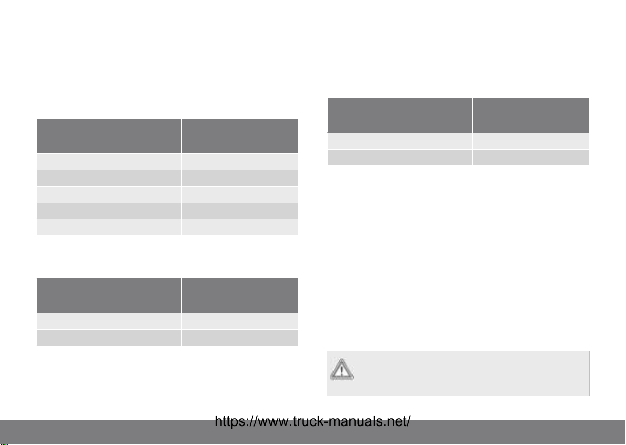
PL*/PS* fuses
Table 6. PL*/PS* fuses
Designations Heavy current (A) Use
F1 100 Traction motor
F2 80 Pump motor
F3 7,5 Manoeuvring
PS, PSH fuses
Table 7. PS, PSH fuses
Designations Heavy current (A) Use
F1 100 Traction motor
F2 125 Pump motor (PS)
160 Pump motor (PSH)
F3 7,5 Manoeuvring
PLP fuses
Table 8. Fuses
Designations Heavy current (A) Use
F1 250 Traction motor
F2 250 Pump motor
F3 7,5 Manoeuvring
Designations Heavy current (A) Use
F4 5 For additional
equipment. Max. 120
W
F5 25 Servo steering
TS fuses
Table 9. TS fuses
Model Heavy current (A) Use
TS 1.1 kW, TS 2 kW 3 Manoeuvring
TS 1.1 kW, TS 2 kW 7,5 Manoeuvring
TS 1.1 kW, TS 2 kW 250 Pump motor
TS 1.1 kW 100 Traction motor
TS 2 kW 160 Traction motor
Maintenance instructions
Genuine replacement parts
Genuine Parts
The reliability that we promise is contingent upon using original
spare parts. Only our genuine replacement parts guarantee
correct operation, long life and the right to a warranty.
55

14SERVICING AND MAINTENANCE
Basic trouble shooting
If the truck does not work after action has been taken in
accordance with the following table, contact an authorised
service technician. Further action should only be carried out by
specially assigned and trained servicing technicians. If an error
code is shown on the diver's display, this must be reported to an
authorised service technician.
Truck condition Possible cause Procedure
The truck does not
start
The battery plug has
not been inserted
The emergency stop
switch/battery
connector is not
connected
The battery capacity
is too low
Fuse defective Change the defective
The key switch is set
to "0" or the truck is
not logged on
Insert the battery plug
Connect the
emergency stop
switch/battery
connector
Charge the battery
fuse
Turn the key switch to
position "I" or enter
the appropriate
Operator ID and
password
Truck condition Possible cause Procedure
The truck cannot be
driven
The truck will not lift
the load
The truck is not ready
for use
The driving seat
switch is not activated
Drive fuse defective
The truck is not ready
for use
The driving seat
switch is not activated
The hydraulic oil level
is too low
The battery capacity
is below 20%
Pump fuse defective Change the defective
The load is too heavy Reduce the load
Carry out all the
actions under the
heading "The truck
does not work"
Sit in the driving seat
P**/TS: Pull down the
tiller arm and stand
on the platform
Change the defective
drive fuse
Carry out all the
actions under the
heading "The truck
will not start"
PLP/TS: Stand on the
platform
Check the level and
top up the hydraulic
oil
Charge the battery
pump fuse
Refer to the maximum
permitted weight on
the machine plate
56
SERVICING AND MAINTENANCE14
Dismantling and assembling the panels
General
WARNING!
The removal and refitting of panels and covers
should be carried out by an authorised service
technician.
WARNING!
Disconnect the main power circuit by pulling out the
battery plug before the covers are removed.
WARNING!
It is not permitted to use the truck with covers and
panels removed.
Removal and installation of the machine housing cover,
PL*/PS*
1) Remove the securing bolts.
2) Hold the cover by the holes in the sides and lift it off.
3) Install in the reverse order.
Removal and installation of the machine housing cover,
PLP
1) Press the emergency stop button.
3) Insert a round rod or similar into the emergency stop
button. Turn the emergency stop button until the hole in
the shaft is found. Then remove the emergency stop
button shank by turning it counterclockwise.
4) Remove the securing bolts.
5) Fold out the gates and remove the panel by working it over
the gates.
6) Install in the reverse order.
Removal and installation of the machine housing cover, TS
1) Remove the securing bolts.
2) Lift off the cover.
3) Install in the reverse order.
Dismantling and assembling wheels
Safety regulations concerning wheel change
WARNING!
For safety reasons, we recommend that wheel
changes only be carried out by an authorised service
technician.
2) Take out the plastic plug from the plastic cover over the
battery.
57
14SERVICING AND MAINTENANCE
WARNING!
For optimum performance and so as not to invalidate
the warranty, use only our genuine replacement
parts! Otherwise, we are unable to guarantee
stability and brake function.
WARNING!
Take care while lifting and securing the truck with a
block, as there is a risk of crushing injury.
Dismantling and assembling the castor wheel, PLL, PLE,
PSL, PSD, PS, PSH
Lift the load wheel off the ground and secure the truck with
blocks.
WARNING!
Ensure that the truck is unable to move while work is
in progress.
1) Remove the plastic cover from the machine housing.
2) Remove the bolts.
3) Take out the castor wheel assembly and support the fork in
a vice.
4) Undo the bolt and drive out the wheel axle. Now the wheel
can be taken out of the fork.
Torque
The bolts must be tightened to a torque of 47
Nm.
Dismantling and assembling the castor wheel, PLP
Lift the load wheel off the ground and secure the truck with
blocks.
WARNING!
Ensure that the truck is unable to move while work is
in progress.
1) Remove the plastic cover from the machine housing.
2) Remove the securing bolts.
3) Take out the castor wheel assembly and support the fork in
a vice.
4) Tap out the retaining pin, drive out the wheel axle and
remove the wheel from the fork.
NOTE!
In connection with a wheel change, the
retaining pin should also be replaced.
5) Install in the reverse order.
5) Install in the reverse order.
58

SERVICING AND MAINTENANCE14
Torque
The bolts must be tightened to a torque of 47
Nm.
Dismantling and assembling the castor wheel, TS
Lift the wheel off the ground and secure the truck with blocks.
WARNING!
Ensure that the truck is unable to move while work is
in progress.
1) Remove the plastic cover from the machine housing.
2) Remove the securing bolts.
3) Take out the castor wheel assembly and support the fork in
a vice.
4) Tap out the retaining pin, drive out the wheel axle and
remove the wheel from the fork.
NOTE!
In connection with a wheel change, the
retaining pin should also be replaced.
5) Install in the reverse order.
Dismantling and assembling the drive wheel
Pull out the battery plug.
1) Loosen the drive wheel nuts, without removing them.
2) Lift the load wheel off the ground and secure the truck with
blocks.
WARNING!
Ensure that the truck is unable to move while
work is in progress.
3) Remove the wheel nuts and remove the drive wheel.
4) Install in the reverse order.
Tighten the wheel nuts crosswise, to:
Torque
PLL, PLE, PSL, PSD, PS, PSH: 80 Nm
Torque
PLP: 84 Nm
Torque
TS: 135 Nm
Torque
The bolts must be tightened to a torque of 47
Nm.
Start the truck and test drive in both directions. The wheel must
not catch or jam.
59
15SAFETY REGULATIONS
The authority and obligations of the truck
driver
The driver has the authority and the responsibility to refuse to
drive the truck in the following cases:
• The truck constitutes a clear safety hazard.
• The load constitutes a clear safety hazard.
• If the truck has been repaired, altered or adjusted without
the changes being approved by the supervisor.
• If the truck driver's physical or psychological condition is
such that he/she can be considered a safety hazard.
The driver has the authority to:
• prevent unauthorized persons from using the truck for
which he/she is responsible. An unauthorized person is
someone who has not received permission from the
supervisor and/or someone who lacks training
• prevent anyone from walking or standing under a raised
lift, whether this is loaded or unloaded.
WARNING!
Take great care in the machinery compartment,
beware of hot surfaces, etc.
Getting in and out
Be careful when getting in and out. Use the handle if one is
installed and take into account the height difference between
the floor and the truck.
WARNING!
It is not permitted to climb on to the truck.
Driving the truck
Driving in public areas
The truck must not be driven on public roads outside a private
area.
Distance between vehicles
Remember that the vehicle in front of you may stop suddenly.
Keep a reasonable distance. Remember that any load on the
forks affects the braking distance.
Pinch risk
WARNING!
Always be careful when using the truck to be aware
of the risk of pinching, both in respect of the driver
and adjacent people.
Passengers
Passengers must not ride on the truck unless otherwise
indicated on the truck.
60
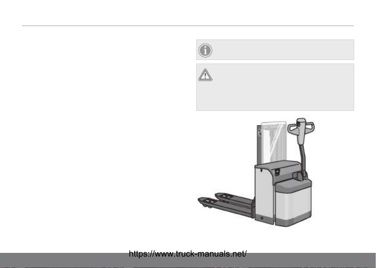
SAFETY REGULATIONS15
Clearance height
Bear in mind that the truck cannot be used where the clearance
height of an opening is less than the height of the drivers cab,
the load or the mast.
The truck in an industrial lift
The truck can only be driven into an industrial lift if this has
been authorised. Make sure that the capacity of the industrial lift
is never exceeded (the total weight of the truck including the
weight of the driver). The driver must be able to escape. Park
inside the lift so that the driver is beside the door. Never place
the truck or the load within the industrial lift's risk zones. Ensure
that the truck's brakes have been engaged before the industrial
lift is started!
Floor load
Carefully check notices or other instructions concerning the
maximum floor load or maximum wheel pressure to ensure that
these are not exceeded. For the truck's total weight, see the
machine plate.
Signalling
Use the signal horn to attract attention.
Reduced vision
Slow down when approaching crossings and other places
where the line of vision is reduced. Avoid driving in the same
direction as the forks if the load in front of you obstructs your
sight. Find someone to help you, if your vision is blocked.
NOTE!
Accessories on the truck may restrict the view.
WARNING!
There is a danger to life if the truck is driven with
insufficient visibility through the finger protection.
Beware therefore of, for example, condensation and
icing, which must be removed before the truck is
driven.
61
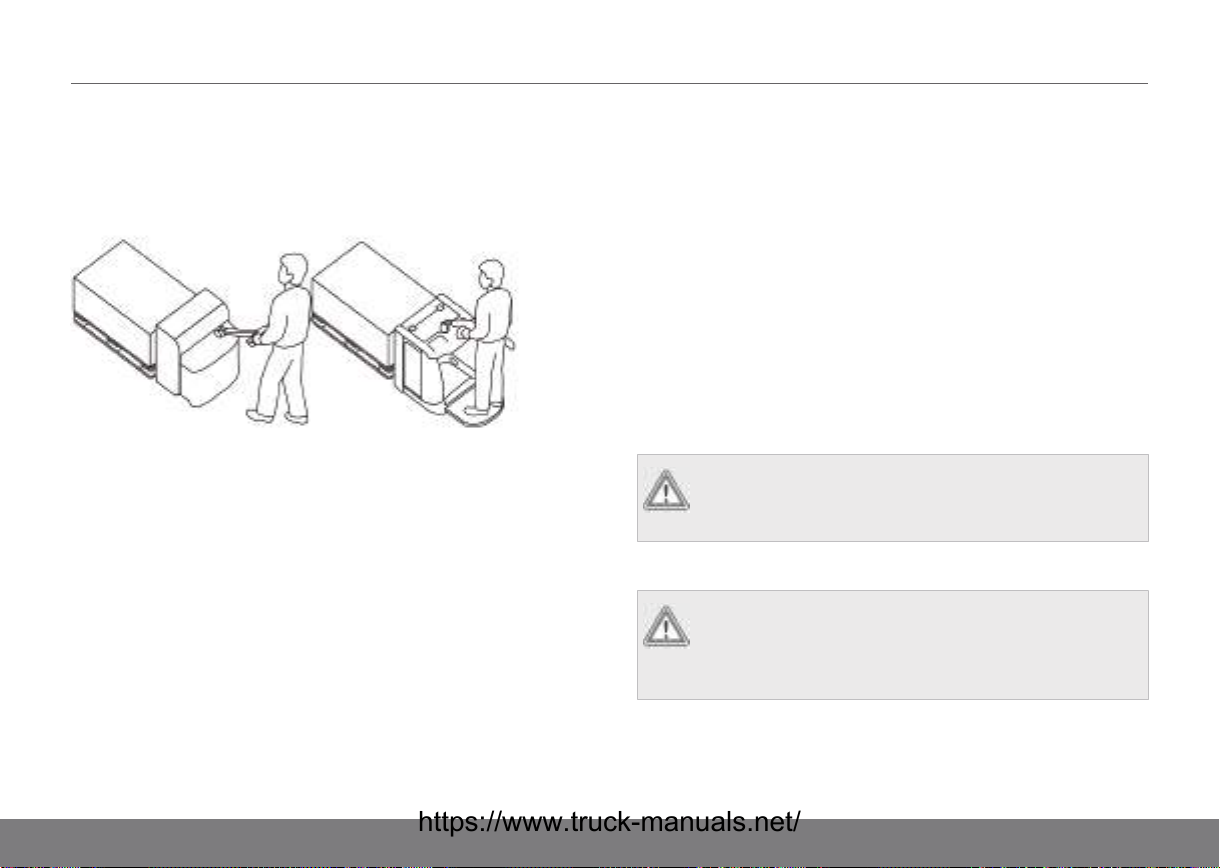
15SAFETY REGULATIONS
Transports
Figure 9. Transport mode
In normal operation, the truck's transport mode must be
observed. It is prohibited to drive with forks raised when moving
loads up and down in shelves and similar.
When transporting loads, the truck should, if possible, be driven
in the opposite direction to the direction the forks are pointing.
This ensures that the operator has a better view if the load is
high, and makes the truck easier to manoeuvre. When driving in
the direction of the forks, the truck is sensitive to any sharp
steering movements (compare with reversing a car). Only drive
the truck with covers and housings closed and locked in place.
Speed
Adjust the speed according to the floor conditions, the line of
sight and operational safety. Avoid rapid acceleration, sudden
braking and cornering at speed; there is a risk for overturning or
that the load will fall off.
Driving space
Ensure that you have sufficient space for the truck - both the
driver and the load - in narrow aisles. Narrow door openings
that will not permit two-way traffic must be entered through the
centre of the opening. Remember that the truck platform, gates
and overhead guard require extra room. Follow the truck paths
marked within the driving area. Remember to keep your whole
body inside the truck perimeter to avoid crushing injuries.
WARNING!
It is not permitted to push material that is on the floor
out of the way by means of the truck's chassis.
Powered trucks equipped with folding platform
WARNING!
Take great care when guiding a pedestrian truck with
a platform, as there is a risk of being crushed
between the truck and surrounding objects.
62

Load guard
SAFETY REGULATIONS15
WARNING!
Place your feet correctly on the platform to avoid
injury.
Figure 10. Correct location Figure 11. Incorrect location
Figure 12. Load guard
The truck may be equipped with load protection if it is to handle
small objects that are at risk of falling down and injuring the
operator or the truck while the load is raised.
WARNING!
Remember that the load guard requires extra lifting
space!
63

15SAFETY REGULATIONS
Risk zones
Do not drive near the edges of loading bays, gangways, etc.
where there is a risk of the truck going over an edge. Be careful
when operating close to colour marked risk zones.
Overturning
If the truck overturns, get out and keep away from it.
Trucks on another vehicle's loading platform or on a
gangway
When the truck is being driven on a ramp from a loading
platform to a lorry bed or trailer, the ramp's bearing capacity
must be checked. There must be devices in place to prevent
the ramp from shifting. The bearing capacity of the vehicle that
is being driven up onto must be checked. There must be
devices (such as brake chocks) in place to prevent the vehicle
from moving. For information on the truck's total weight, see the
truck's machine plate.
Direction of travel when driving on slopes
Outrigger trucks
These trucks are always driven unloaded with the forks facing
away from the crown of the hill or slope.
When driving with a load on an incline, keep the forks facing the
top.
Awareness!
Always be aware of personnel in the neighbourhood when
operating the truck.
Transportation security
A. PLL, PLE, PSL, PSD, PLP,
TS
When a truck is to be transported, it must be secured at the
defined transportation points. All trucks are to be secured by a
strap across the forks. If the truck has an overhead guard or a
mast that is higher than 2.5 m, a strap must also be secured
over the overhead guard/mast. Chocks can be placed against
the chassis in every direction to prevent rolling or sliding.
B. PS, PSH
64
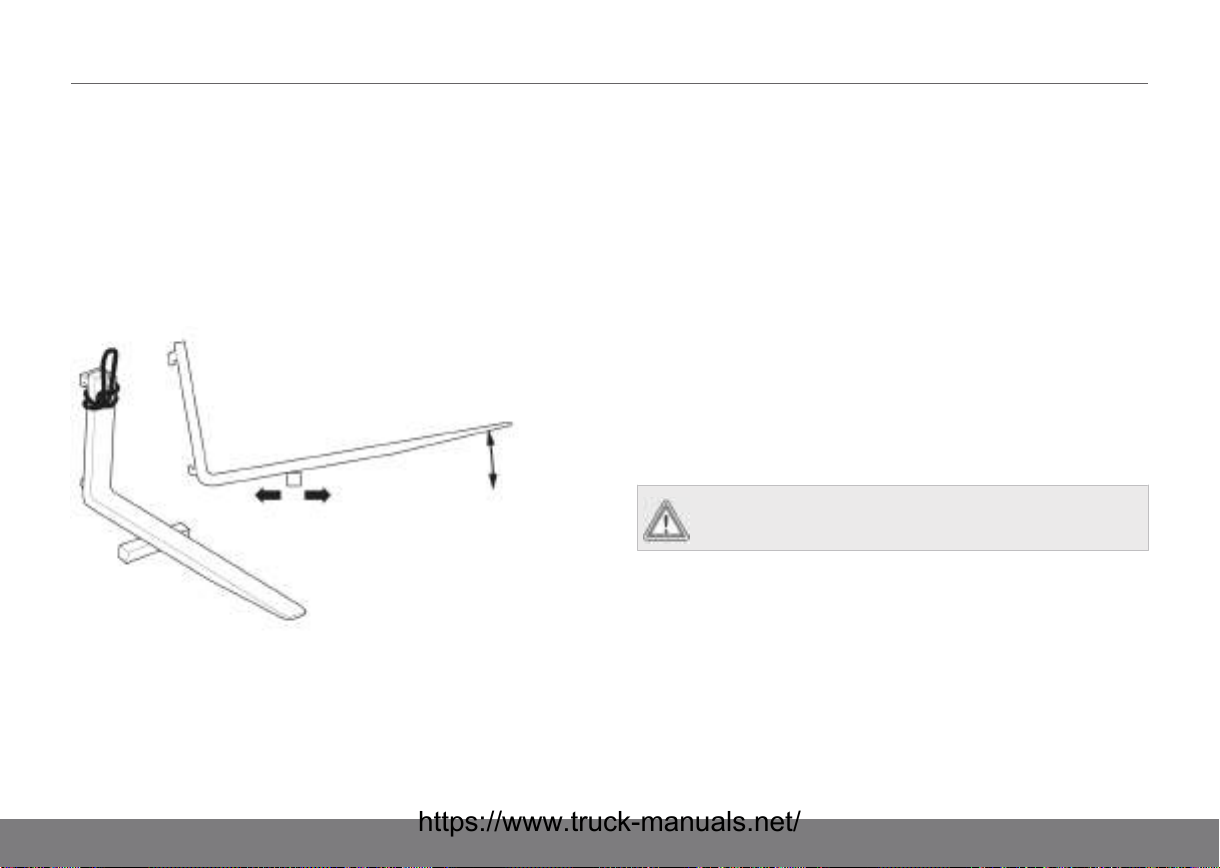
SAFETY REGULATIONS15
PS, PSH: Open the battery cover and thread the strap under it
so that the cover is not damaged by the pressure.
Lifting the forks
Unsecured forks may be lifted by means of a strop intended for
the purpose, as in the illustration. The forks are fitted and
removed by being balanced on a piece of wood and pulled or
pushed by hand off or on to the truck.
Normal operating conditions
Stacking must be carried out on firm, clean and level ground.
Exceptional operating conditions
When the operating conditions differ from the normal conditions
above, the following steps must be taken:
• If the working conditions are of a permanent nature, an
agreement must be drawn up with the supervisory
authority and any other party concerned.
• If the working conditions are of a temporary nature, take
suitable measures, such as using a larger truck, or
reducing the load appropriately.
Work in hazardous environments
A truck operating in an area where there is a risk of fire,
explosion, or in any other high risk area, must be specially
equipped for the purpose.
WARNING!
A truck is not normally equipped for these situations.
Parking
The truck must never be left unattended other than when in the
intended parking space. The truck should always be parked on
level ground. The parking brake must always be engaged. The
forks must be lowered to their lowest position so that nobody
can trip on them. Always turn off the truck so that it is cannot be
operated. If the truck is equipped with a PIN code, the truck
should be "logged off" so that a new code is required to restart,
thereby preventing unauthorised use. See section Switching off
65

15SAFETY REGULATIONS
the truck page 34. If the truck is equipped with a key switch,
the key must be taken out when leaving the truck, so that
unauthorised persons cannot use it. Fire insurance terms
dictate whether or not the key should be taken out at the end of
work. Check!
If the truck is left unused for a prolonged period without it being
recharged, e.g. between two shifts, the battery plug must be
disconnected.
CAUTION!
Do not block access to fire fighting equipment or fire
doors by parking the truck or placing goods in front
of them.
When lifting the truck
General
The truck may only be lifted using lifting eyes directly intended
for lifting. The image shows where the permitted lift points are
located on the truck. The lift points are marked with a decal
showing a lifting hook.
When the truck is being lifted up with a jack, make sure that it is
secured with blocks. The truck must not rest on the jack during
operation.
WARNING!
If the truck is lifted incorrectly, parts may be
damaged by being subjected to excessive force.
When lifting truck types PLL, PLE, PSL, PSD
66
WARNING!
Lifting of the truck should only be carried out by an
authorised service technician.
The illustration below shows where the jack should be placed.

SAFETY REGULATIONS15
When lifting a PLP truck
The illustration below shows where the jack should be placed.
When lifting truck types PS/PSH
67

15SAFETY REGULATIONS
When lifting TS trucks
When lifting a TS truck that has free view frames, the lifting
holes in the outer mast must be used (point B)
On machines with other mast types the lifting strap is attached
round the upper mast strut (point C).
Assembling and putting into service
WARNING!
Assembling/dismantling and putting the truck into
service may only be carried out by an authorised
service technician.
The following actions are to be taken in order to make the truck
ready for use.
• Charge the battery.
• Perform an inspection in accordance with Daily
maintenance (before each shift) page 40.
• Visually inspect the truck, including the forks, for signs of
damage.
• Check that the safety and warning signs are in place and
are legible. See Safety and warning signs page 71.
Temporarily taking the truck out of service
Storage
If the truck is to be taken out of service for more than a month, it
should be stored indoors in dry and frost-free premises.
Actions before storage
1) Clean the truck.
2) Clean and charge the battery in accordance with the
battery manufacturer's maintenance instructions.
3) Check the oil level in the hydraulic system by looking at the
markings on the truck, or alternatively by pushing all the
hydraulic cylinders to their fully extended positions. Top up
the oil if necessary.
4) Check the braking effect on the main brake and parking
brake.
68

SAFETY REGULATIONS15
5) Lubricate the truck in accordance with the lubrication chart.
6) Disconnect the battery plug.
Actions during storage
1) Charge the battery and check the cell electrolyte levels
about every second month.
Putting back into service after storage
1) Clean the truck.
2) Clean and charge the battery in accordance with Battery
changing page 22.
3) Check the gearbox and hydraulic oil levels.
4) Lubricate the truck in accordance with the lubrication chart.
5) Connect the battery plug.
6) Carry out a weekly inspection in accordance with Weekly
inspection page 41.
WARNING!
The truck should only be put back into service by an
authorised service technician.
Taking the truck out of service
If the truck is out of action and cannot be operated from the
driver's seat using normal driving controls, contact the
supervisor immediately.
In consultation with an authorised service organisation, the
supervisor must make sure that the move can take place in a
controlled manner, so that there is no risk of accident. The truck
is moved using another truck of sufficient capacity to a suitable
place where the repair can take place. The truck must be lifted
using the specified lift points, see When lifting the truck page
66.
WARNING!
Ensure that the truck cannot fall over or slide off the
forks while being moved.
Swinging loads
The truck is not equipped to handle hanging loads that may
start to swing.
Installing the fire extinguisher
The fire extinguisher is to be installed in a suitable location so
that it is easily accessible without interfering with the view or
becoming a collision hazard in the case, for example, of severe
braking.
WARNING!
It is not permitted to drill into the overhead guard
pillars or the overhead guard itself.
69

15SAFETY REGULATIONS
In the event of accidents
Report all accidents or incidents immediately to the supervisor.
If possible, leave the truck where it is. If possible, take action to
lessen the damage or harm, especially if there are people hurt.
Avoid actions that might hinder accident investigation. In
general, you must await the decision of the supervisor.
Noise/Sound levels
Noise levels at the driving position are lower than 70 dB(A)
measured in accordance with European standard EN 12053.
Vibrations
Vibration data for truck models (tested in accordance with EN
13059+A1:2008).
PLP
TS
F = 0.63 m/s², measuring accuracy Cv 0.09
w,z
F = 0.62 m/s², measuring accuracy Cv 0.10
w,z
Climatic conditions
The normal operating temperature in which the truck is
designed to operate in is in the range of +1°C to +25°C. Max
short term temperature +40°C, min short term temperature
-25°C.
Work platforms
When temporarily lifting persons with a truck without driver
lifting, national regulations and recommendations for working
with work platforms must be complied with.
Overhead guard
It is not permitted to remove the overhead guard from a truck
which is equipped with one.
Protective shoes
Protective shoes must be worn when working with trucks
according to applicable national standards.
Lighting
Work lighting facilitates work in poor light conditions. Work
lighting is available as accessory for many models.
Additional units/Trailers
If, after delivery, it is decided to equip the truck with additional
units, towing hitch equipment for trailers or other accessories
which could influence the stability or braking capacity of the
truck, an authorised representative of the truck manufacturer
must be contacted. Before the truck is assembled, it must have
been approved by its manufacturer, see Truck modification
page 7.
70

SAFETY REGULATIONS15
Safety and warning signs
General
NOTE!
There are a number of warning signs on the truck.
Always replace signs that are damaged or missing.
Explanation of symbols
Crushing risk
between moving parts
Do not stand under
the forks
Passengers are only
allowed at the
designated positions
on the truck (platform)
Read and comply with
the Instruction
Handbook before
operating the truck.
Do not stand on the
forks
Read and comply
with the Instruction
Handbook before
operating the truck.
71

15SAFETY REGULATIONS
Only one person is
allowed on the truck
Locations of safety and warning signs on PLE, PSL,
PSD, PS, PSH
72
A. Only applies to PL*/PS*
without mast.

SAFETY REGULATIONS15
Locations of safety and warning signs on PLL
Europe
A. Only applies to PLL with
battery on rollers.
USA
A. Only applies to PLL with
battery on rollers
73
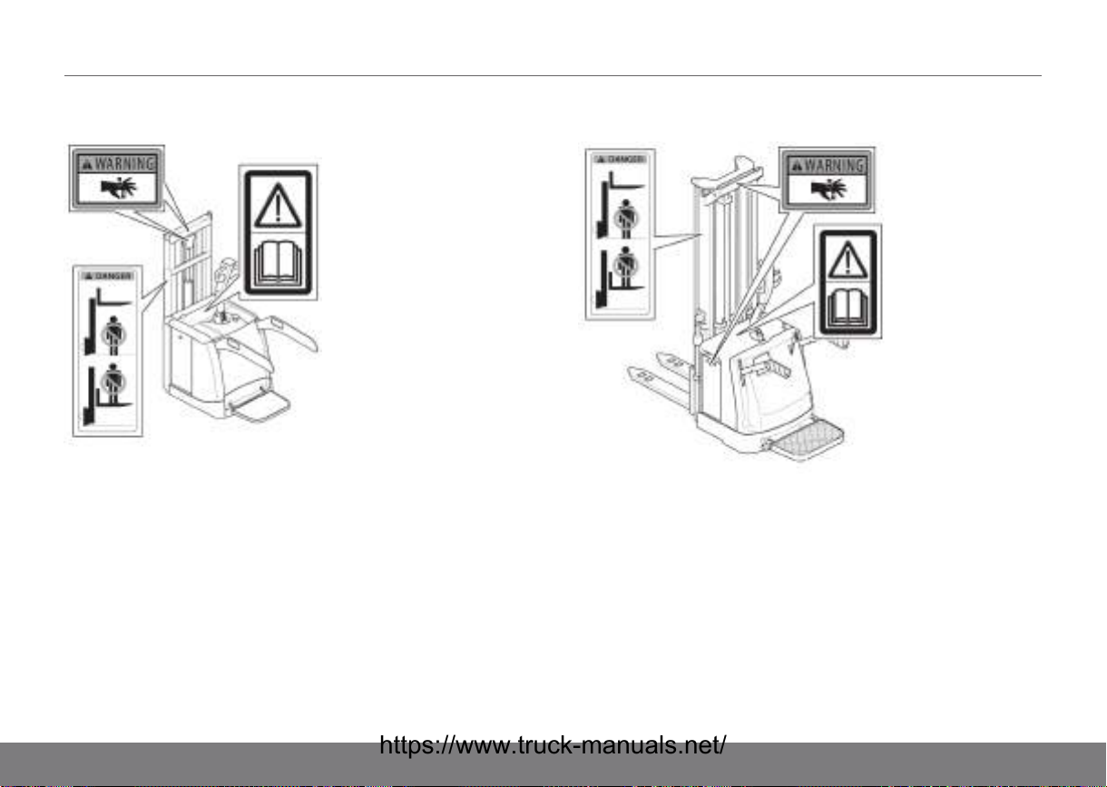
15SAFETY REGULATIONS
Locations of safety and warning signs on PLP Locations of safety and warning signs on TS
74
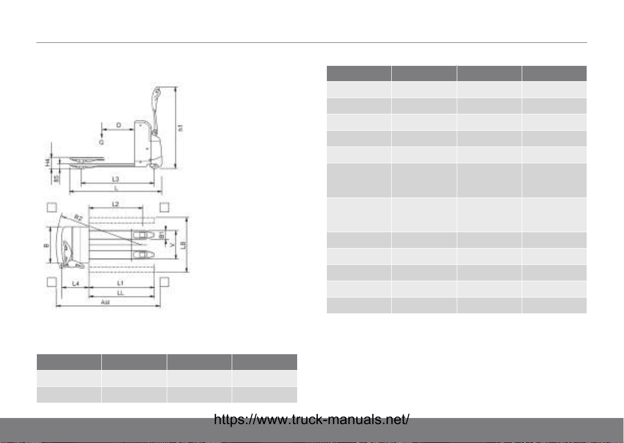
DIMENSIONS16
Dimensions PL*/PS*
Figure 13. Positions for dimensions PLL
Table 10. Truck type and dimensions in mm
Measurements PLL 145 PLL 180 PLL 200
D 600 600 600
H4 205 205 205
Measurements PLL 145 PLL 180 PLL 200
R2 1385/1575 1385/1575 1385/1575
H6
L 1495/1685 1495/1685 1495/1685
B 660 660 660
L1 1000/1190 1000/1190 1000/1190
V (width over
forks, std
max-min)
V (width
between fork
shanks)
L4 495 495 495
B1 160-48 160-48 160-48
H1 85 85 85
L2 785-975 785-975 785-975
L3 1128/1318 1128/1318 1128/1318
520/680 520/680 520/680
200/360 200/360 200/360
75

16DIMENSIONS
Figure 15. Positions for dimensions PSD/PSL
Figure 14. Positions for dimensions PLE
76
Table 11. Truck type and dimensions in mm
Measurements PLE PSD 125/160 PSL
D 600 600 600
H4 730
H3 880
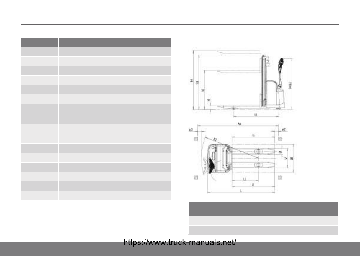
DIMENSIONS16
Measurements PLE PSD 125/160 PSL
H5 1090
H2 210
R2 1710 1755 1755
L 1770 1873 1873
B 660 660 660
L1 1200 1200 1200
V (width over
forks, std
max-min)
V (width
between fork
shanks)
L4 570 673 673
B1 184-60 185-65 185-65
H1 88 92
B2 166 175
L2 990 990 950
L3 1412 1510 1510
534 540 540
170 170
Dimensions PS, PSH
Measurements PSH 200
SDTFV
H5 4118-5918 4130-5930 3105-4010
H4 3600-5400 3600-5400 2690-3590
PSH 200
BDTFV
PS 125 TV/TFV
77
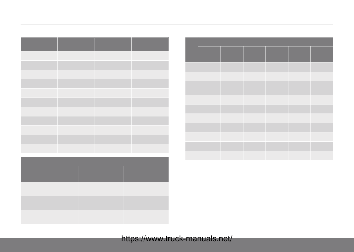
16DIMENSIONS
Measurements PSH 200
H3 1738-2338 1735-2335 1845-2300
H1 90 60 90
L 2030 2000 1700/1900
L1 1000/1150 800/1000/1150 1000/1200
L2 650/800 732 752
L3 1498 1480 1282
L4 880 880 700
R2 1675 1663 1665
B1 195x70 100x50 170x65
B2 180 855 -
V 570 316-773 550
Mea
sure
SDTFV BDTFV BT ST STFV BTFV
men
ts
H5 4112-
5912
H4 3600-
5400
H3 1740-
2340
SDTFV
41255925
36005400
17402340
21834713
16704200
13752640
PSH 200
BDTFV
PSH 160
21704700
16704200
13752640
PS 125 TV/TFV
21704700
16704200
13752640
34134713
29004200
19902640
Mea
sure
SDTFV BDTFV BT ST STFV BTFV
men
ts
H1 90 60 60 90 90 60
L 1980 2000 2000 1980 1980 2000
L1 1000/1150800/1000
L2 650-800 743 743 650-800 650-800 743
L3 1448 1430 1430 1448 1448 1430
L4 830 830 830 830 830 830
R2 1625 1613 1613 1625 1625 1613
B1 170x70 170x70 170x70 170x70 170x70 170x70
B2 265 855 855 265 265 855
V 560 316-773 316-773 560 560 316-773
/1150
PSH 160
800/1000
/1150
1000/11501000/1150800/1000
/1150
78
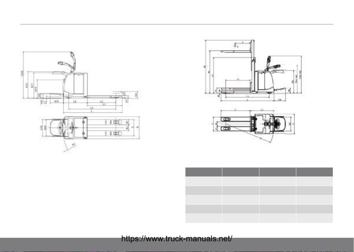
Dimensions PLP
Figure 16. PLP
DIMENSIONS16
Figure 17. PLP CD
Table 12. Truck type and dimensions in mm
Measurements PLP 200 PLP 250 PLP 200 CD
H5 2095
H4 205 205 1675
H3 1410
H1 85 85 90
R2 770+L2 835+L2 1900
79
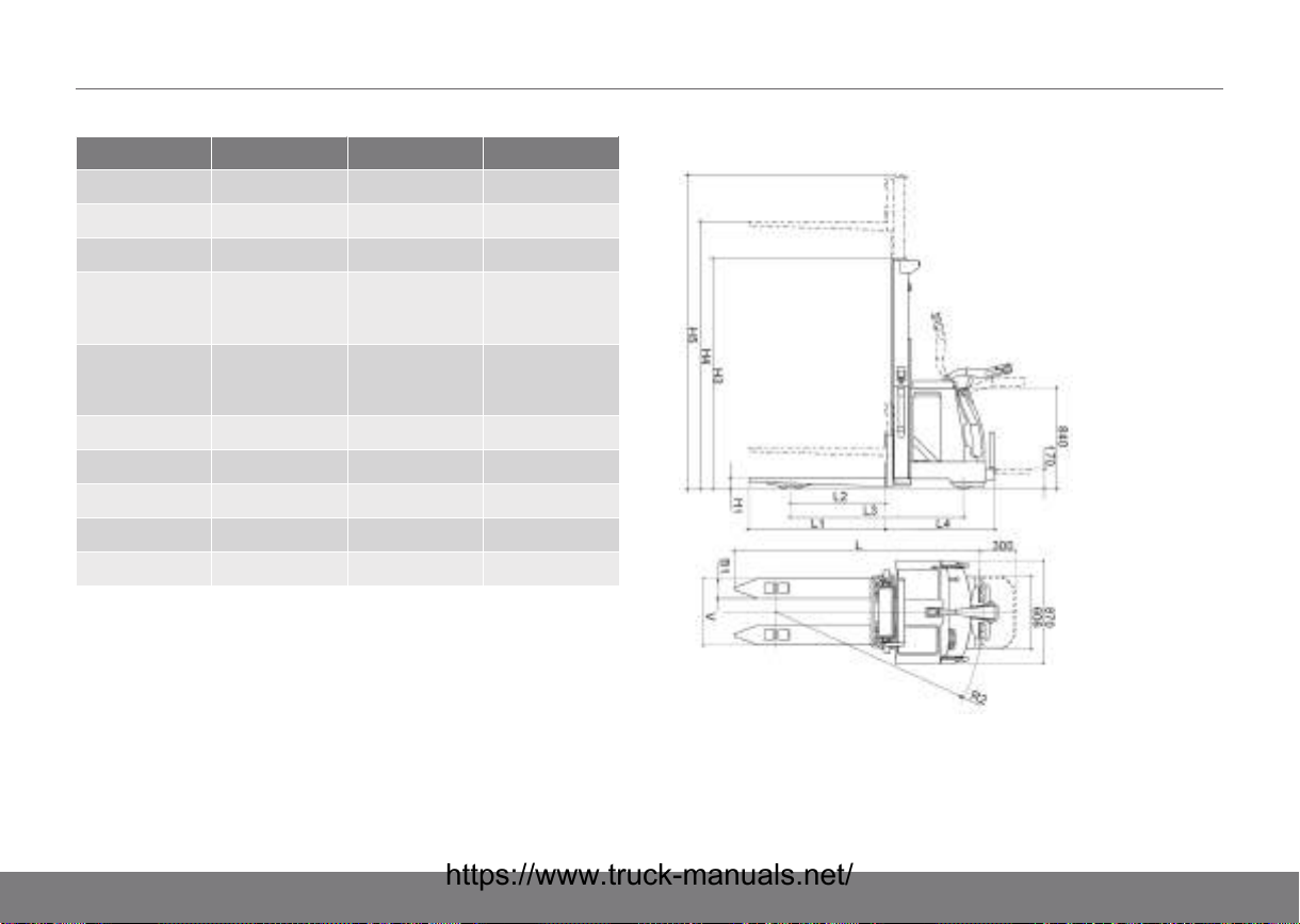
16DIMENSIONS
Measurements PLP 200 PLP 250 PLP 200 CD
L 750+L1 825+L1 2085
B 770 770 770
L1 1000/2375 1000/2375 1150
V (width over
forks, std
max-min)
V (width
between fork
shanks)
L4 750 825 934
B1 175x55 175x55 185x65
H1 85 85 90
L2 785-1765 785-1465 958
L3 551+L2 626+L2
680/460 680/480 560
V-350 V-350 190
Dimensions TS
80

DIMENSIONS16
Table 13. Truck type and dimensions in mm
Measur
ements
H5 3100-
H4, T 1670-
H4, TV 2690-
H4, TFV 1670-
H4,
DTFV
H3 1840-
H2 170 203 203 170 203 203
H1 90 90 90 90 90 90
L L1+L4 L1+L4 L1+L4 L1+L4 L1+L4 L1+L4
L1 1200 1000/11501000/11501200 1000/11501000/11
L2 750 650/800 650/800 750 650/800 650/800
L3 1335 1473 1473 1335 1473 1473
L4 901 959 959 819 877 877
R2 1674 1784 1784 1569 1679 1679
120 140 150 120 140 150
4005
3590
2295
TSP TSL
21704700
4200
4200
36004800
13752640
21704700
16704200
16704200
36005400
13752640
31004005
26903590
18402295
21704700
16704200
16704200
36004800
13752640
21704700
16704200
16704200
36005400
13752640
50
Measur
ements
B1 170x65 170x55 170x55 170x65 170x55 170x55
V 550 560 560 550 560 560
120 140 150 120 140 150
TSP TSL
81

17WEIGHT
Weight PLL, PLE, PSL, PSD, PS, PSH
Truck Service weight with/without
battery (kg)
PLL 145 460 / 280
PLL 180 460 / 280
PLL 200 465 / 285
PLE 565 / 405
PSL 775 / 550
PSD 125/160 800 / 560
Weight PS, PSH
Truck Service weight with/without
battery (kg)
PS 125 TV 915 / 740
PS 125 TFV 930 / 755
PSH 160BDTFV 1350 / 1050
PSH 160SDTFV 1300 / 1000
PSH 200BDTFV 1600 / 1300
PSH 200SDTFV 1550 / 1250
PSH 160BT 1350 / 1050
PSH 160ST 1300 / 1000
Truck Service weight with/without
battery (kg)
PSH 160STFV 1300 / 1000
PSH 160BTFV 1350 / 1050
Weight PLP
Truck Service weight with/without
battery (kg)
PLP 200 860 / 530
PLP 200 CD 1106 / 810
PLP 250 925 / 545
Weight TS
Truck Service weight with/without
battery (kg)
TSP 120 TV 1070 / 800
TSP 140T 1120 / 850
TSP 140TFV 1230 / 960
TSP 140DTFV 1230 / 960
TSP 150T 1120 / 850
TSP 150TFV 1230 / 960
TSP 150DTFV 1230 / 960
82

WEIGHT17
Truck Service weight with/without
TSL 120 TV 1070 / 800
TSL 140T 1120 / 850
TSL 140TFV 1230 / 960
TSL 140DTFV 1230 / 960
TSL 150T 1120 / 850
TSL 150TFV 1230 / 960
TSL 150DTFV 1230 / 960
battery (kg)
83
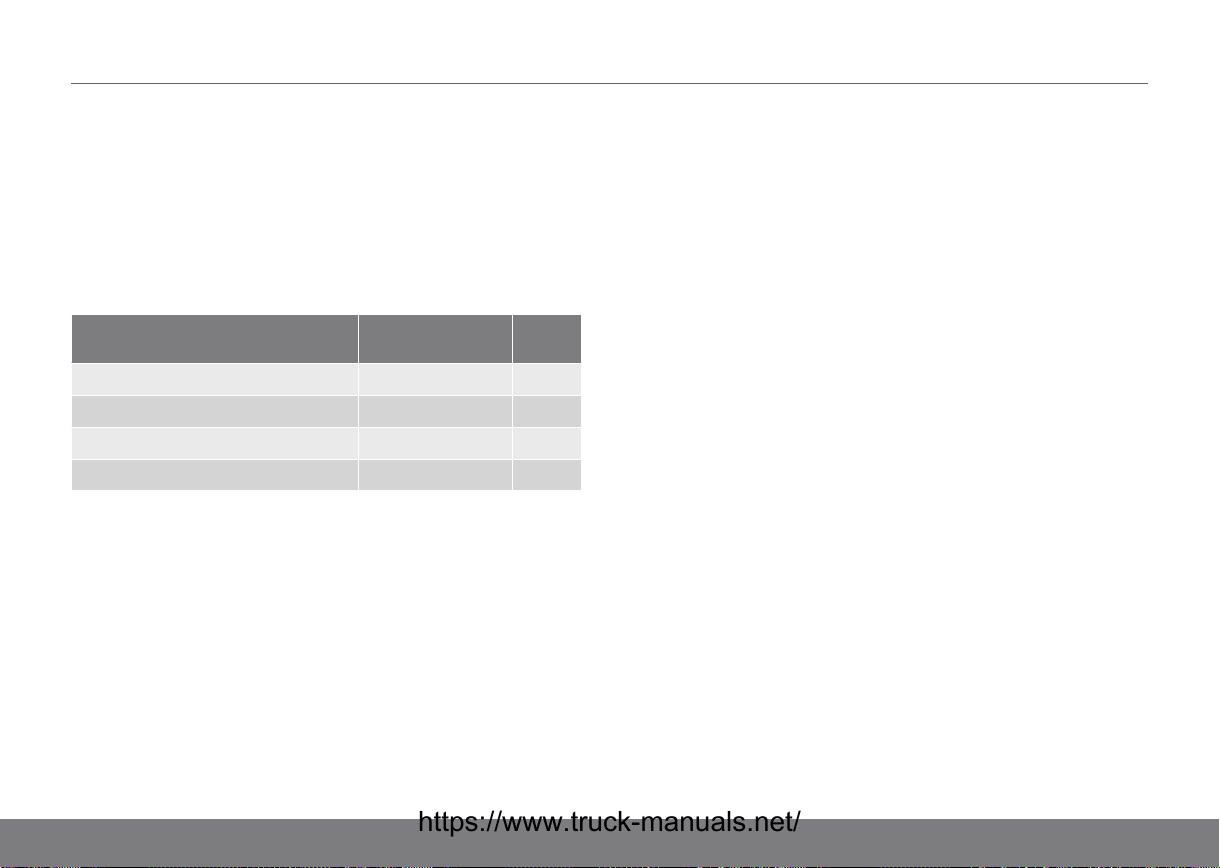
18ORDERING HANDBOOKS AND MANUALS
Ordering a Spare Parts Manual
We do not automatically send out spare parts catalogues with
delivery of your truck. It is possible to order a Spare Parts
Manual via your local distributor, for a fee. Delivery time is
estimated at around three weeks.
Complete the order form below and send it to your local
distributor.
TRUCK TYPE P/N QUANT
ITY
PLL/PSD/PSL/PLE 159249
PLP 159250
PS/PSH 159251
TS 005937
Name
......................................................................................................
Company
......................................................................................................
Address
......................................................................................................
Country
Tel
......................................................................................................
Fax
......................................................................................................
......................................................................................................
84
 Loading...