

Page 1

No. OMFBE-N44140
OPERATOR’S MANUAL
FORKLIFT TRUCK
MODELS 1F1/1F2
It is the responsibility of the Operator and Supervisor to read and understand this manual.
•
Protect the earth and be kind to your lift truck.
•
Page 2

TO OPERATORS
A Word to UniCarriers FORKLIFT Operators
This ORIGINAL OPERATORS MANUAL describes operating procedures,
daily checks and simple maintenance for safe usage of your UniCarriers
FORKLIFT. We urge you to read this ORIGINAL OPERATORS MANUAL carefully before operating a UniCarriers FORKLIFT to familiarize
yourself with the safety instructions. An operator of any industrial truck
should maintain safety as the number one priority at all times. These instructions will not only reduce mechanical issues with a forklift, but may
also save a life.
If you encounter any problems with a UniCarriers FORKLIFT, contact an
authorized UniCarriers FORKLIFT dealer in your area and request a
complete checkup. The dealership will ensure that your forklift is serviced in accordance with the latest factory approved methods. This
ORIGINAL OPERATORS MANUAL is not a training manual, it is a guide
to help trained and authorized operators safely operate this forklift.
Please consult your employer for proper training on the appropriate use
of this forklift while performing your job. Illustrations in this ORIGINAL
OPERATORS MANUAL will show the operator the correct procedures
for checking, starting, operating and stopping this forklift.
UniCarriers Corporation
1-2, Shin-Ogura, Saiwai-ku,
Kawasaki, Kanagawa,
212-0031, Japan
All information, specifications and illustrations in this ORIGINAL OPERATORS MANUAL are based on the latest data obtainable at the
time of publication. UniCarriers Corporation reserves the right to
make changes or improvements at any time without notice.
This ORIGINAL OPERATORS MANUAL has been prepared on the assumption that your forklift is fully equipped (including all optional equipment). Thus, if you have any questions regarding equipment, please
contact an authorized UniCarriers FORKLIFT dealer.
©2015 UniCarriers Corporation
1
Page 3

Dear Owner of a UniCarriers Truck:
Original Instruction Manual
The Original Instruction Manual contains information that You, as user of the truck, must be aware of in order to avoid/minimise the risk of injury/
damage to yourself and the truck. You are also responsible to the company management, other people and objects in your environment. You should
therefore read through this manual before starting the truck for the first time.
Our products are constantly being developed and renewed, we therefore reserve the right to make alterations without prior notice.
Thank you for choosing UniCarriers Corporation as your truck supplier.
UniCarriers Corporation service
As the owner of a UniCarriers truck, we also welcome you to our service organisation.
We offer support and advice for any problems that may arise and assistance with servicing and ordering of replacement parts. Refer to the nearest
authorised sales agent or service workshop for assistance.
Truck driving courses
The importance of goods handling for the company and the environment increases every year, at the same time ever more technical solutions are
developed and introduced on our trucks. It is therefore important that the driver, who has a key role to play in goods handling, is given the correct
conditions to operate as safely and efficiently as possible. Statistics show that the number of incidents decreases significantly when a truck driver
has been properly trained. Please contact us for information about the training package.
Throughout this manual we have used the symbol:
- followed by the word WARNING. This is used to indicate the presence of a hazard which may cause the possibility of a personal injury or
- CAUTION.
other damage and must be followed precisely.
This is also used throughout the manual to indicate the presence of a hazard that could cause possible injury to yourself or components
and the procedures must be followed carefully.
It should be kept in mind that this ORIGINAL OPERATORS MANUAL deals with both standard and optional equipment, and so you may come
across issues that are not applicable to your model in particular.
2
Page 4

TRUCK MODIFICATION
NOTE:
Unauthorized forklift modification is not
permitted.
No modifications or alterations to a powered industrial forklift, which may affect,
for example, capacity, stability or safety requirements of the forklift shall be made
without the prior written approval of
UniCarriers FORKLIFT, its authorized representative or a successor thereof.
Contact an authorized UniCarriers FORKLIFT dealer before making any modification
or alteration to your industrial forklift that
may affect, for example, braking, steering,
visibility and the addition of removable attachments.
After receiving the approval of UniCarriers
FORKLIFT, its authorized representative or
a successor thereof, the capacity plate, decals tags, operation and maintenance
handbooks shall also be changed appropriately.
Only in the event that UniCarriers FORKLIFT is no longer in business and there is
no successor in the interest to the business, the user may arrange for a modification or alteration to a powered industrial
forklift, provided however, that the user
shall:
A. Arrange for the modification or altera-
tion to be designed, tested and implemented by an engineer(s) expert in
industrial forklifts for their safety;
B. Maintain a permanent record of the de-
sign, test(s) and implementation of the
modification or alteration;
C. Approve and make appropriate chang-
es to the capacity plate(s), decals, tags
and instruction handbook;
D. Affix a permanent and easily visible la-
bel to the forklift stating the manner in
which the forklift has been modified or
altered together with the date of the
modification or alteration, and the name
and address of the organization that
performed the alterations.
3
Page 5

Contents
To Operators ...............................................................................................1
TRUCK modification ....................................................................................3
Name of components ..................................................................................5
Operator’s qualifications and protective equipment for operating forklift .....5
Safety rules..................................................................................................6
Traveling on gradients, gangways and in elevators ..................................10
Transporting forklift....................................................................................12
Approach angle, departure angle and gangway ........................................12
Special operating conditions......................................................................14
Installation of attachments.........................................................................14
Position of labels .......................................................................................14
Instruments and controls ...........................................................................20
Changing meter display.............................................................................21
Selector lever position ...............................................................................24
Setting the time..........................................................................................25
Setting the date .........................................................................................26
Explanation of warning lamps....................................................................28
LCD warning symbols................................................................................29
Inspection timing display ...........................................................................30
Displays when malfunction occurs ............................................................30
LPG remaining time management.............................................................34
Switches and controls ...............................................................................37
Starting and operating ...............................................................................47
Loading and unloading .............................................................................. 61
Function tests ............................................................................................63
SEAT (except for EU region)..................................................................... 65
Seat (for EU region) ..................................................................................68
Top panel lock ...........................................................................................72
Daily care and inspection ..........................................................................80
Maintenance.............................................................................................. 91
Maintenance schedule ............................................................................105
Putting forklift in storage.......................................................................... 108
Daily checks ............................................................................................110
UniCarriers FORKLIFT genuine parts .....................................................110
Disposal of parts and materials ...............................................................111
Precautions for using LPG model............................................................ 111
Periodic maintenance schedule ..............................................................125
Identification numbers .............................................................................129
Diesel particle filter [DPF] (option for diesel forklift only) ......................... 131
Specifications ..........................................................................................139
Noise level............................................................................................... 153
Index........................................................................................................ 156
4
Page 6
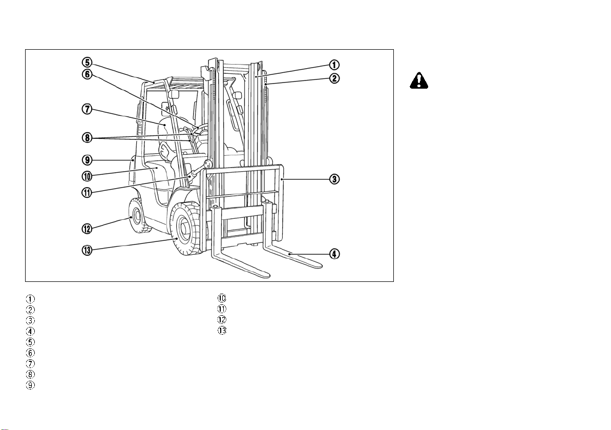
NAME OF COMPONENTS OPERATOR’S QUALIFICATIONS
WARNING:
MOM1872
AND PROTECTIVE EQUIPMENT
FOR OPERATING FORKLIFT
OPERATOR’S QUALIFICATIONS
The forklift shall be operated in accordance
with the operations of the operator’s license and the applicable provisions of the
local laws and regulations.
Mast
Lift chain
Backrest
Fork
Overhead guard
Steering wheel
Operator’s seat
Control lever
Counterweight
Top panel
Tilt cylinder
Rear tire
Front tire
5
Page 7
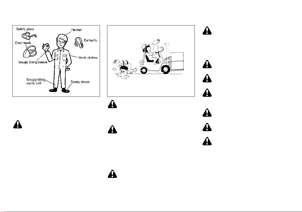
PERSONAL PROTECTIVE
WARNING:
MOM0015
MOM0128
EQUIPMENT FOR OPERATING
FORKLIFT
For operation of the forklift, the protec-
tive equipment for the operator shall be
dependent upon the conditions of use
and the applicable provisions of the local
laws and regulations.
The working clothes worn by the opera-
tor shall be such that sleeves and cuffs fit
snugly so as to prevent them from getting caught on forklift levers, etc., and
safety glasses, earmuffs, dust mask and
safety shoes should also be worn, as required by the work environment or employer.
SAFETY RULES
Operator must be trained and authorized to drive the forklift and must understand safety techniques and rules
for forklift operation.
Inspect the forklift before operating.
Do not operate the forklift if it is in
need of repair. If it is in need of repair, tag the forklift, remove the key
and report the condition to the proper authority. Do not attempt repair
unless you are trained and authorized to perform repairs.
Do not remove the overhead guard or
backrest.
6
Make sure that the selector lever is
set in neutral and the parking brake
is applied before turning the ignition
switch. Do not start or operate the
forklift if you are not in the designated operator’s position.
Do not allow anyone on any part of
the forklift while moving or lifting.
Do not sit on the fork (when loaded
or not) or get under the fork.
Before operation, make sure that the
seat belt is secure and the top panel
latch is in the locked position.
Before starting the engine, make
sure that the seat belt is secure.
1F1/1F2 models do not have the
creeping phenomena.
The forklift will not move if the selector lever is in the F (forward) or R (reverse) position unless you depress
the accelerator pedal. When depressing the accelerator pedal, be sure to
visually confirm the position of the
selector lever. When starting on
slopes, be sure to apply the parking
brake to hold the forklift and then
start, even if the slopes are gentle.
Avoid rapid acceleration (especially
when carrying a high load).
Page 8
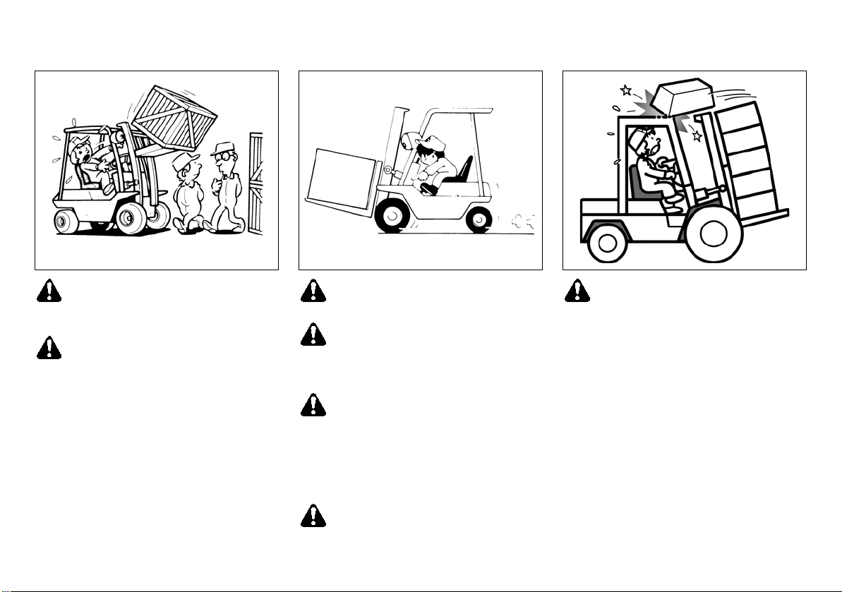
Keep hands, feet and other parts of
MOM0129
MOM0130
MOM1677
your body inside the operator’s compartment at all times.
Do not allow anyone to stand or walk
under the elevated portion of the
forklift whether it is empty or loaded.
Space forks as far apart as the load
will permit.
Always carry loads low with the mast
tilted to the backmost position, never
forward. Do not elevate loads except
during stacking.
Maintain a careful lookout for people
and obstructions, and watch the path
of travel. Watch clearances, especially overhead and tail swing. When
visibility is obstructed, use extreme
caution. Yield the right of way to pedestrians.
If the load obstructs the front view,
drive the forklift in reverse.
7
Do not place a load higher than the
backrest of the forklift. A load placed
higher than the backrest may drop
towards the operator and is very dangerous. If such a load must be handled, securely fasten the load using
suitable ropes or hold-down bands.
Page 9
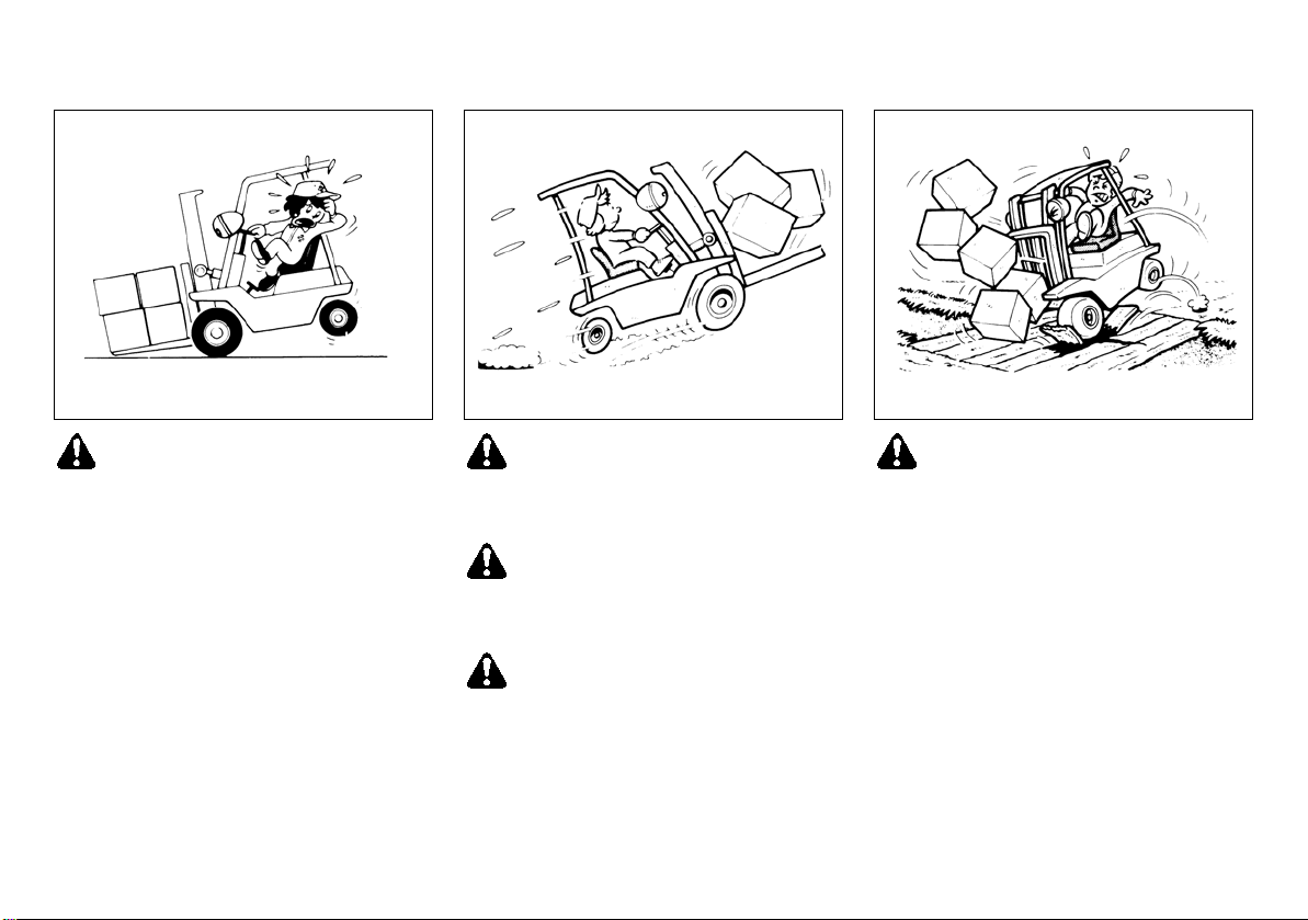
Do not overload the forklift. Check the
MOM0131
MOM0132
MOM0133
load chart for load weight and load
center information. Always pick up
loads as close to the center of the
weight as possible to avoid off-center
loading.
Avoid sudden starts, stops or turns.
Slow down for turns and on uneven
or slippery surfaces that could cause
the forklift to overturn or slide.
Use special care when traveling without a load as the risk of lateral overturn may be greater than when
traveling with a load.
Before entering forklifts or trailers,
be certain that the brakes on the forklift or trailer are applied and the
wheel chocks are in place or that the
trailer is locked to the loading dock.
8
Before driving over a dockboard or
bridge plate, be certain that it is properly secured. Drive carefully and
slowly across the dockboard or
bridge plate. Never exceed its rated
capacity.
Page 10
Use special care when operating on
MOM0134
MOM0135
slopes. Travel slowly and do not angle across or turn.
When ascending or descending
slopes, drive the forklift with the load
facing upgrade.
Fuel is highly flammable.
It must be handled with the utmost
care, in accordance with the safe
handling requirements of fuels and
the applicable safety provisions of
the local laws and regulations.
When filling the tank with fuel, make
sure that the forklift is properly
parked. Turn off the ignition switch
and remove the key.
When fuel is spilled, wipe the area
clean with a cloth. The cloth shall be
disposed of in accordance with the
requirements of safe handling of fuels, environmental requirements and
the applicable provisions of the local
laws and regulations.
Do not handle unstable or loosely
stacked loads. When handling long,
high or wide loads, use special care
to ensure stability and carefully
watch the surrounding conditions.
When approaching cross aisles,
slow down and sound the horn if visibility is obstructed.
Before leaving the forklift, be sure
that forks or attachments are lowered, the selector lever is in neutral,
the hand brake is applied and the ignition switch is turned off. Avoid
parking the forklift on a slope.
9
Page 11
WARNING:
WARNING:
When filling the tank with fuel or re-
MOM0136
MOM0016
charging the battery, stop the engine
and place the forklift only in a designated area with good ventilation.
Keep away from arcs, sparks, flames
or lit cigarettes.
Do not breathe exhaust gases: they
contain colorless and odorless carbon monoxide. Carbon monoxide is
a dangerous gas and can cause unconsciousness or death.
TRAVELING ON GRADIENTS, GANGWAYS AND IN ELEVATORS
When moving the forklift in elevators,
check to make sure that the elevator is
capable of withstanding the forklift
weight or the forklift weight plus the load
weight.
Be sure to apply chocks under the tires
to prevent the forklift from moving while
it is parked in the elevator.
Do not perform work in the elevator.
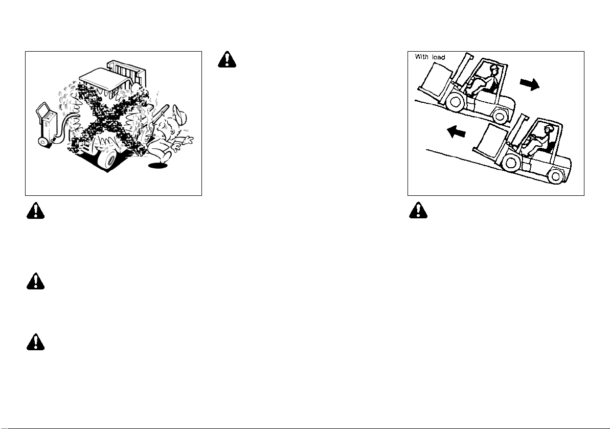
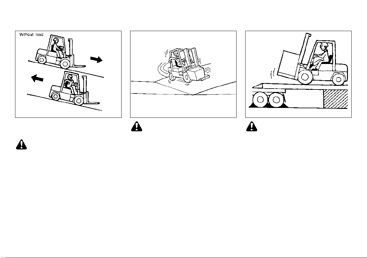
Use care when traveling on gradients.
When traveling on gradients with a load,
always drive forward on upward slopes
and in reverse on downward slopes.
Drive slowly on slopes. Drive in the re-
verse direction on upward slopes when
without a load, and drive forward on
downward slopes.
Do not run the engine in closed spaces or poorly ventilated rooms such
as a garage or refrigerator, etc.
10
Page 12
Use the brake pedal when driving down-
WARNING:
WARNING:
MOM0017
MOM0018
MOM0019
hill to sufficiently reduce the speed.
Use the brake pedal and engine
brake together when driving downhill so as to maximize the effectiveness of the engine brake.
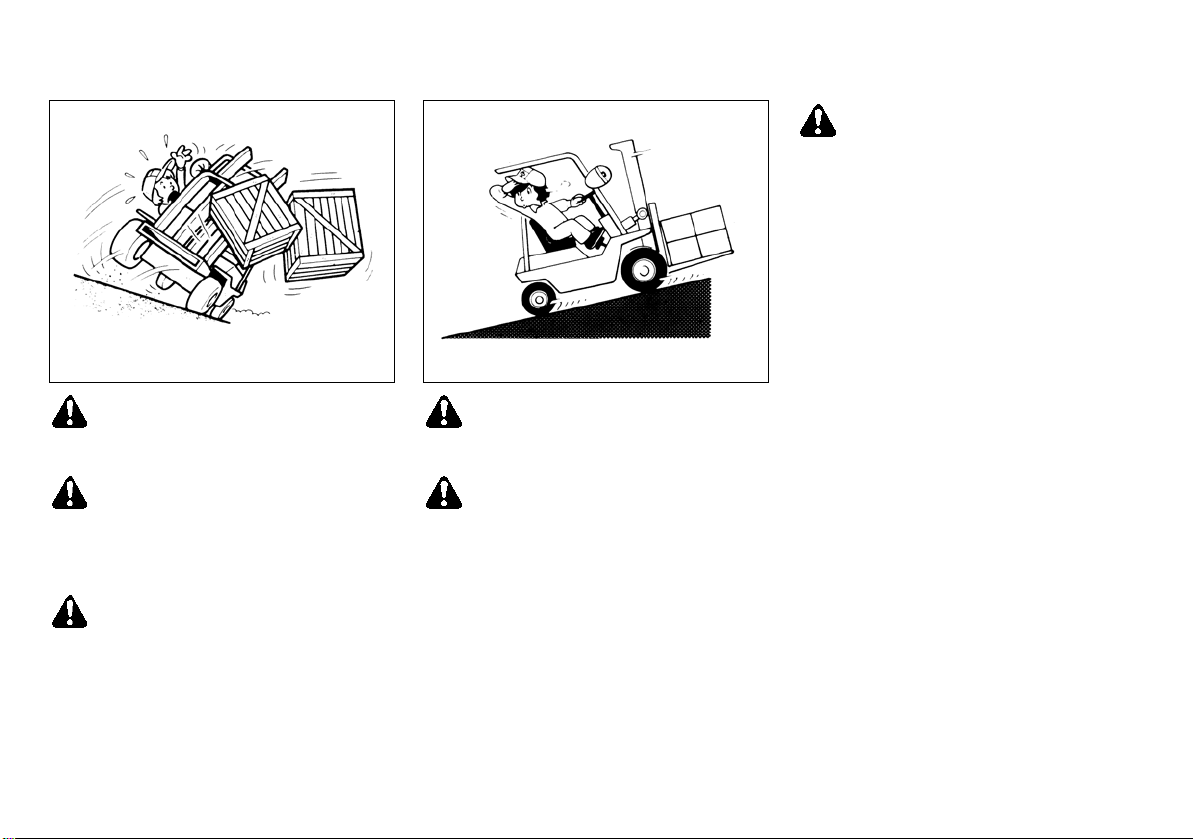
Do not traverse and turn around on slopes.
Because driving on slopes causes the
center of gravity to shift towards the lowest point, the forklift is likely become unbalanced.
Following are precautions relating to driving onto freight cars and trailers.
Check freight cars and trailers to make
sure that they will not move.
The ramp for driving the forklift onto a
freight car or trailer shall have sufficient
strength to withstand the weight of the
forklift and its load, as well as the forces
exerted by the bouncing of the forklift.
The ramp shall be anchored so that it
does not shift.
Use the utmost care when driving on and
off a freight car or trailer.
11
Page 13
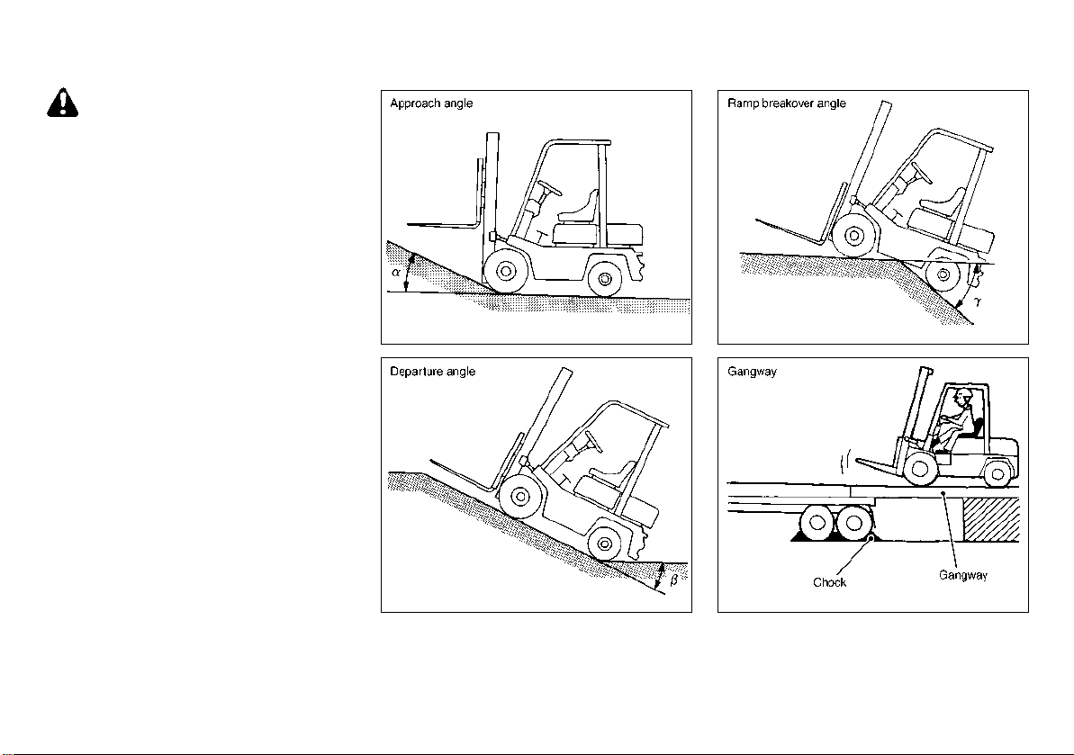
TRANSPORTING FORKLIFT APPROACH ANGLE, DEPARTURE
WARNING:
MOM0020
MOM0021
MOM0022
MOM0023
ANGLE AND GANGWAY
1. Tilt the mast back to the maximum without load.
2. Check the approach and departure angles to make sure that the underside of
the forklift does not come into contact
with the load carrying platform or the
ground.
3. When using a load bridge, make sure
that the planks are capable of withstanding the deadweight of the forklift.
4. When winching the forklift onto a load
carrying platform, be sure to attach the
cable to the traction pin. Do not ride on
the forklift while it is being winched.
5. Be sure to use lashing points and firmly
secure the forklift to the load carrying
platform.
6. When hoisting the forklift, be sure to
use the lifting points.
7. Turn off the ignition switch and remove
the key.
8. Make sure that the battery connector is
disconnected.
12
Page 14
WARNING:
The following precautions should be
MOM2796
closely observed to ensure safe operation of the forklift as well as to prevent
personal injury.
Always make sure your seatbelt is securely fastened, and stay seated while
driving.
Read the manual carefully before operating the truck to familiarize yourself
with the safety instructions.
DANGER:
The operator should stay inside the
forklift if the forklift starts to tip or falls
off a dock or ramp.
The operator should:
Lean away from the point of impact.
Hold on firmly to the steering wheel
with both hands.
Brace your feet and keep yourself inside the operator compartment.
Do not jump outside of the forklift.
13
Page 15

SPECIAL OPERATING CONDITIONS
WARNING:
WARNING:
When operating the forklift under severe climatic conditions such as high temperatures,
high altitudes, in cold storages, and when handling explosives and combustibles, and in areas where the forklift is apt to cause radio
interference, make sure that the forklift is manufactured and approved as conforming to the
local specifications, laws and regulations.
INSTALLATION OF ATTACHMENTS
Before installing hook-on attachments, be
sure to read the installation manual issued
by the attachment manufacturer to assure
correct and proper installation. Contact an
authorized UniCarriers FORKLIFT dealer
for the revised load capacity figures.
POSITION OF LABELS
When warning and caution labels are damaged such that they cannot be read or have
peeled off, they should be immediately replaced with new labels to ensure that they
are constantly maintained in a legible condition. The warning and caution labels are
available at an authorized UniCarriers
FORKLIFT dealer.
The warning and caution labels are affixed
to the designated locations of the forklift as
shown in the figure on the following page.
Before operating the forklift, be sure to take
note of the details given in the labels so as
to ensure proper and safe operation.
14
Page 16
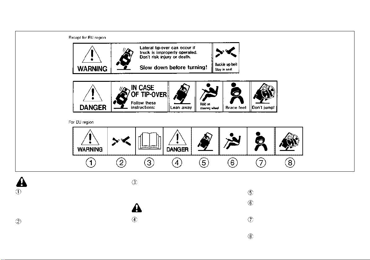
POSITION OF WARNING AND CAUTION LABELS
MOM3254
15
Page 17
WARNING:
Do not stand on or below forks.
WARNING:
MOM2675
MOM2676
Riding on the forks is strictly prohibited.
Furthermore, do not stand immediately
below the forks. Otherwise, serious accidents can occur if the forks should move
abruptly and the load placed on the forks
unexpectedly falls down. In the worst
cases, these accidents can be fatal.
Be sure to keep your hands, feet and body
away from the masts. Otherwise, parts of
the body are liable to become caught between the moving and fixed sections of the
masts and injury may occur.
16
Page 18
WARNING:
Operation precautions
MOM2807
This label contains instructions on how
to operate the forklift safely and avoid accidents. Therefore, be sure to take careful note of the instructions before
operating the forklift.
17
Page 19

WARNING:
The following precautions should be
MOM2796
closely observed to ensure safe operation of the forklift as well as to prevent
personal injury.
Always make sure your seatbelt is securely fastened, and stay seated while
driving.
Read the manual carefully before operating the truck to familiarize yourself
with the safety instructions.
DANGER:
The operator should stay inside the
forklift if the forklift starts to tip or falls
off a dock or ramp.
The operator should:
Lean away from the point of impact.
Hold on firmly to the steering wheel
with both hands.
Brace your feet and keep yourself inside the operator compartment.
Do not jump outside of the forklift.
18
Page 20

WARNING:
Never open the radiator cap while it is hot.
WARNING:
WARNING:
MOM2748
MOM2808
MOM2346
Touching the radiator cap while it is hot may
result in injury to your hand.
Never touch the cooling fan while it is turning.
Touching the cooling fan while it is turning may
result in injury to your fingers, and in the worst
case, may sever the fingers.
Diluted sulfuric acid and lead are used in
the battery.
Used battery fluid and batteries shall be
disposed of according to the applicable
provisions of the local laws and regulations.
Consult with an authorized UniCarriers
FORKLIFT dealer about the disposal of
the used battery fluid and batteries.
19
Page 21
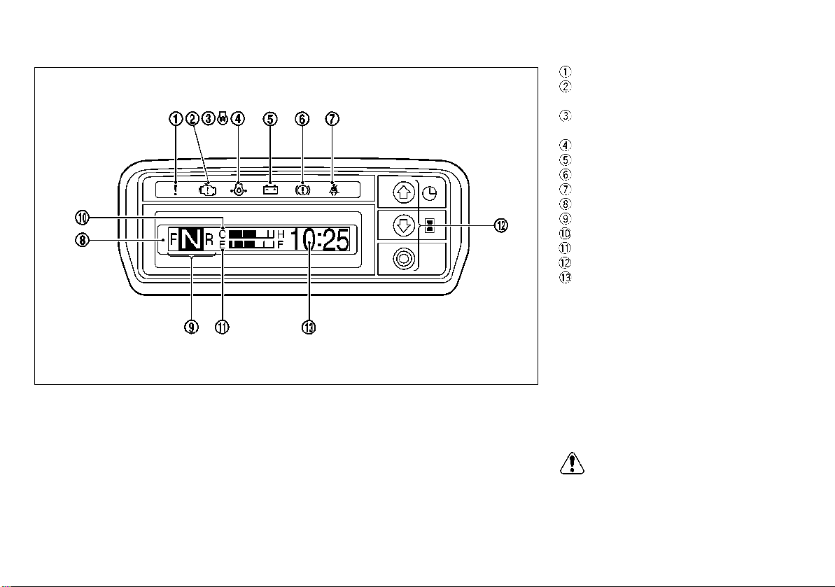
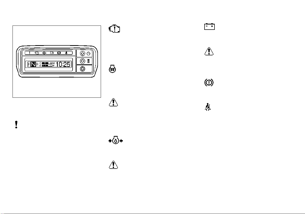
INSTRUMENTS AND CONTROLS
CAUTION:
MOM2196
Multipurpose warning lamp
Engine check lamp
(gasoline/LPG engine forklifts only)
Glow pilot lamp
(diesel engine forklifts only)
Oil pressure warning lamp
Charge warning lamp
Parking brake warning lamp
Seat belt warning lamp
Liquid Crystal Display (LCD)
Selector lever position (left side of LCD)
Water temp. gauge (top center of LCD)
Fuel gauge (bottom center of LCD)
Operation buttons
Time (right side of LCD)
NOTE:
In place of the time, the date or hour me-
ter may be displayed.
While driving, this display changes to
the speedometer when the vehicle speed
is 4.0 km/h (2.5 MPH) or higher.
This display also indicates the inspec-
tion/service timing, malfunctions and
warnings.
The display time and date will be reset if the
battery cable is disconnected or the battery
is replaced. If the display has been reset,
set the time and date again.
20
Page 22
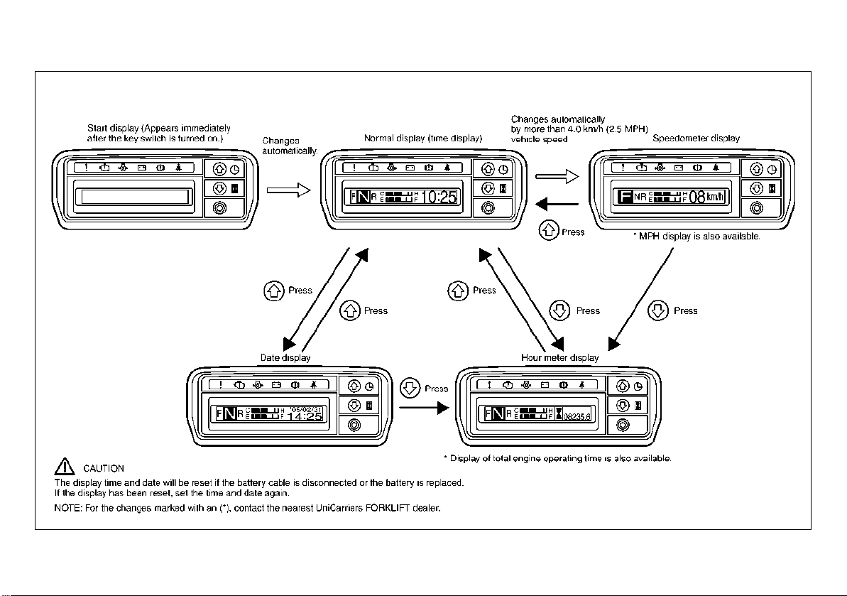
CHANGING METER DISPLAY
MOM2978
21
Page 23
METER ILLUMINATION
CAUTION:
MOM2198
MOM2199
An illumination lamp is provided for meters to
ensure visibility at night.
OPERATION BUTTONS
Use these buttons to change the display, make
settings (time and date) and enter the password.
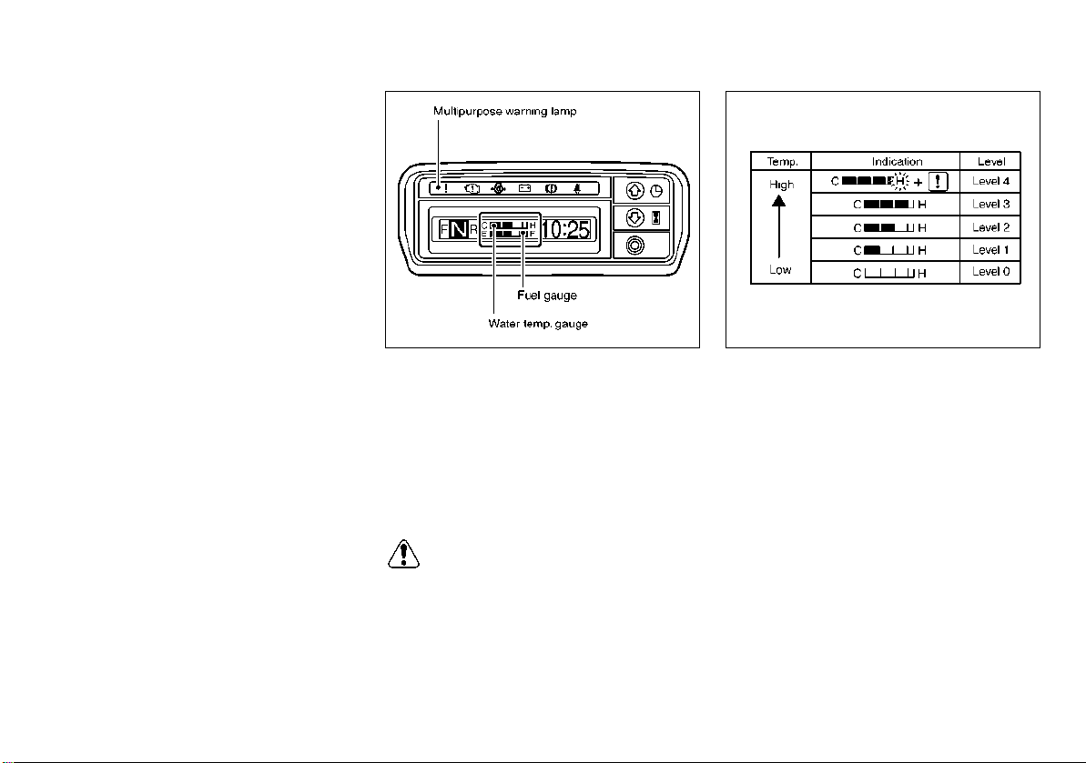
WATER TEMP. GAUGE
Indicates the current water temperature in levels 0 - 4. When level 2 is indicated, the coolant
temperature is correct. When the indication
reaches level 4, the display begins to blink,
and the multipurpose warning lamp illuminates
to inform the operator of the high water temperature.
If level 4 is indicated, stop the forklift and
allow the engine to cool while idling. After
the engine has sufficiently cooled down,
turn the engine off, and check the coolant
level and fan belt deflection.
22
Note to the operator:
All ECCS forklifts in North America have a
creep home feature that will reduce engine
RPMs if the coolant temperature remains
near the “H” position. This indicates that
the unit should be serviced by an authorized UniCarriers FORKLIFT dealer.
Page 24
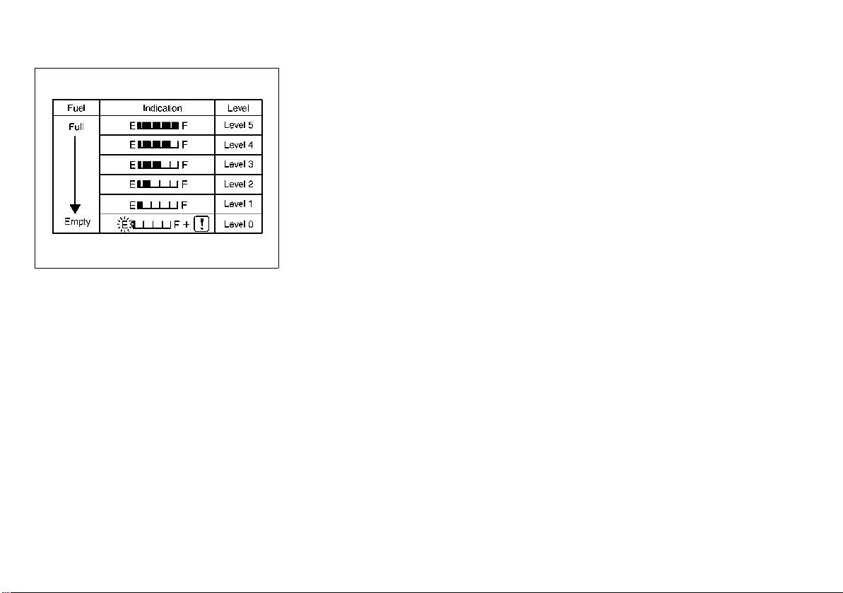
FUEL GAUGE
MOM2200
Indicates the current fuel level in levels 0 - 5.
When level 5 is indicated, the fuel tank is full.
When the indication reaches level 0, the display begins to blink, and the multipurpose
warning lamp illuminates to inform the operator of the nearly empty fuel tank. The fuel tank
is nearly empty. Add fuel immediately.
NOTE:
If the forklift is an LPG - gasoline dual
fuel vehicle, the fuel meter will not work
when the forklift is operated with LPG.
When operating the forklift with LPG,
check from time to time to be sure that
the LPG level warning lamp is not lit and
that the LPG level alarm is not on.
To check the remaining amount of LPG,
use the fuel gauge on the LPG cylinder.
23
Page 25
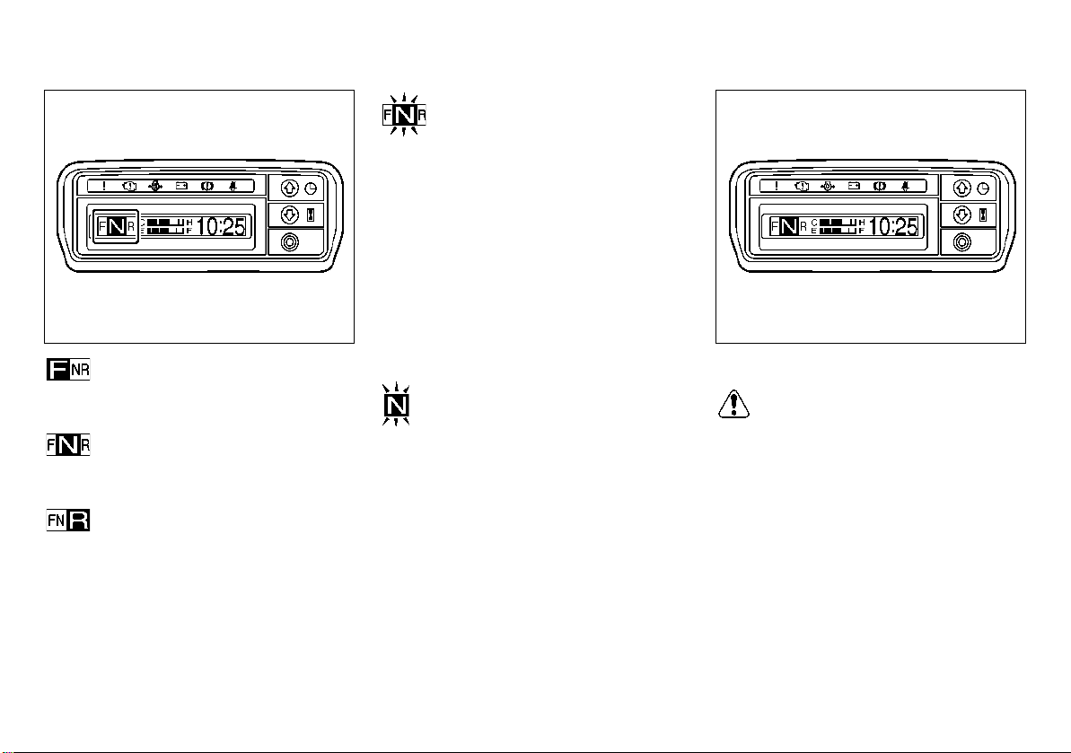
SELECTOR LEVER POSITION
CAUTION:
MOM2201
MOM2202
When the selector lever is in the “F” position,
the display appears as shown here.
When the selector lever is in the “N” position,
the display appears as shown here.
When the selector lever is in the “R” position,
the display appears as shown here.
When the selector lever is in the “F” or “R”
position and the operator is not seated on
the operator’s seat, the display blinks.
Sit on the operator’s seat and shift the
selector lever to Neutral (N), then shift it
again to Forward (F) or Reverse (R) in order
to drive.
When there is an error in the selector lever
signal, the display blinks.
Contact an authorized UniCarriers FORKLIFT dealer and request an inspection.
MTM
[N] illuminates only when the selector lever is
in the “N” position.
When there is an error in the selector lever
signal, the display blinks.
Contact an authorized UniCarriers FORKLIFT dealer and request an inspection.
CLOCK
The time and date will be reset if the battery
cable is disconnected (for example, when
the battery is replaced). Set the time and
date again.
When the ignition switch is turned on, the start
display appears, followed by the normal display (clock display).
NOTE:
Press the buttons to change the display to
the date or hour meter.
24
Page 26
SETTING THE TIME
CAUTION:
MOM2384
MOM2385
NOTE:
Press the button to change from
hours minutes confirmed.
Press both the and buttons at
the same time to return to the previous
display.
Press the button to change the
number up.
Press the button to change the
number down.
DATE
The time and date will be reset if the battery
cable is disconnected (for example, when
the battery is replaced). Set the time and
date again.
Press the button on the normal display
(clock display) to change from the time display
to the date display. Press again to return
to the normal display.
25
Page 27
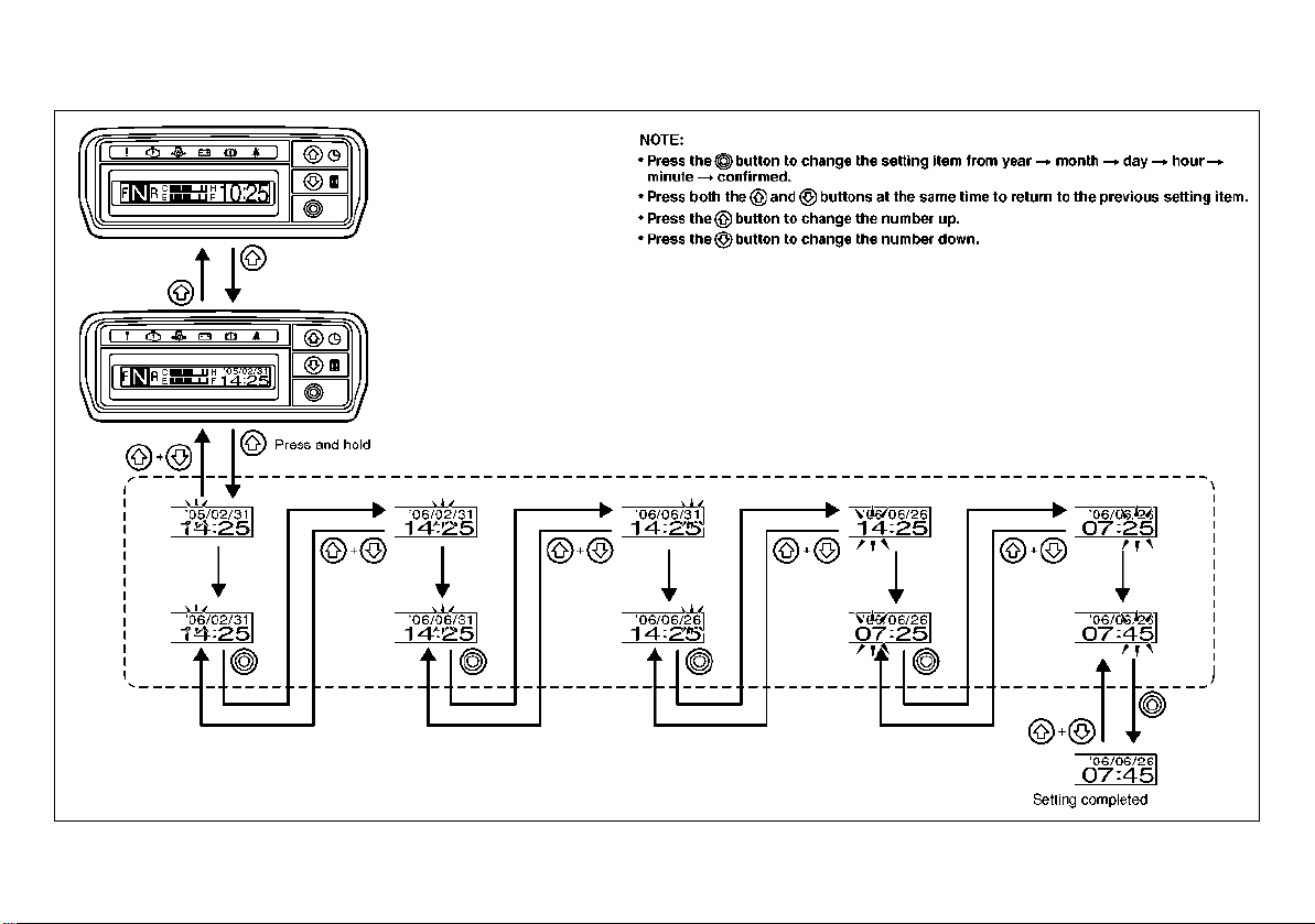
SETTING THE DATE
MOM2205
26
Page 28
HOUR METER
MOM2206
The buttons can be used to change from the
normal display (clock display) to the hour meter display.
The hour meter ordinarily displays the total ignition time that the ignition is on, however it is
possible to change the display to the total engine operating time.
To change the hour meter totaling pattern,
contact an authorized UniCarriers FORKLIFT
dealer.
27
Page 29
EXPLANATION OF WARNING
CAUTION:
CAUTION:
CAUTION:
MOM2207
LAMPS
Following is an explanation of the meaning
and method of correction when a warning lamp
illuminates.
Multipurpose warning lamp
This warning illuminates when one of the LCD
warning symbols illuminates. It also illuminates
when the water temperature is high or the fuel
level is low. If this lamp illuminates during operation, stop operation immediately, report to
the person having management duties and
take necessary measures.
Malfunction indicator lamp
(gasoline/LPG engine forklifts
only)
This warning illuminates when there is malfunction with an engine sensor or air-fuel ratio
control.
Glow plug indicator lamp
(diesel engine forklifts only)
This warning illuminates when the ignition
switch is turned on, and it turns off when glow
plug preheating is completed.
If the lamp remains illuminated after the
glow plugs are preheated, this indicates
a malfunction in the glow system.
Have the system checked at your nearest
authorized UniCarriers FORKLIFT dealer.
Oil pressure warning lamp
This warning illuminates when the oil pressure
is low.
If the lamp illuminates under ordinary operating conditions, stop the engine immediately
and check the engine lubrication system.
Charge warning lamp
This warning illuminates when there is a malfunction with the charge system.
If the lamp illuminates or flickers occasionally during normal operating conditions,
the alternator and electrical system should
be checked.
Parking brake warning lamp
This warning illuminates when the parking
brake lever has been pulled.
Seat belt warning lamp
This warning illuminates when the seat belt is
not fastened.
28
Page 30
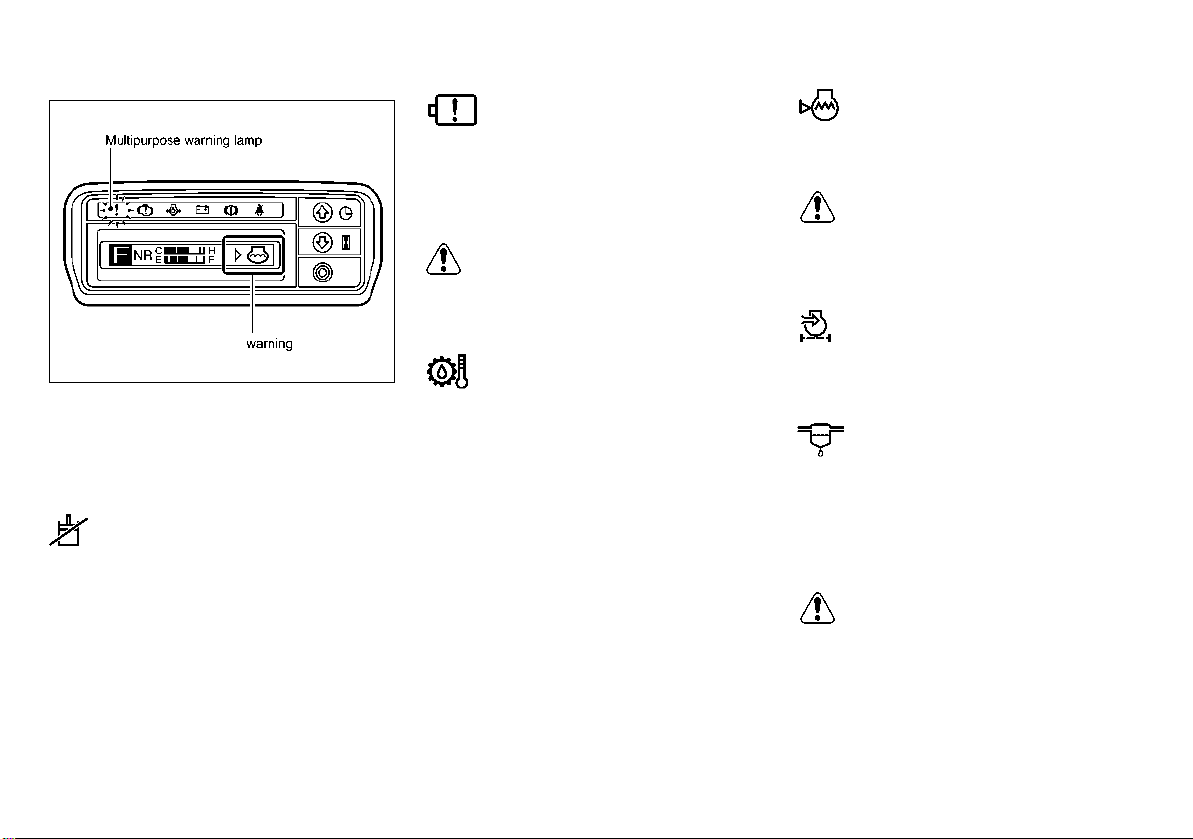
LCD WARNING SYMBOLS
CAUTION:
CAUTION:
CAUTION:
MOM2208
When a forklift warning occurs, a warning symbol and the multipurpose warning lamp illuminate. Following is an explanation of the
meaning and method of correction when a
warning symbol illuminates.
Mast interlock warning
This warning illuminates when the ignition
switch is turned on and the operator is not
seated on the seat. Loading operation is prohibited at this time. Loading becomes possible
when the operator is seated on the seat.
LPG level warning/LPG rack
lock warning (LPG and DUAL
forklifts only)
This warning illuminates when the LPG level is
low. Replace the LPG fuel cylinder before the fuel
(LPG) runs out.
The LPG tank is out of or nearly out of fuel.
Have LPG cylinder tank replaced immediately.
Torque converter fluid temp.
warning
This warning illuminates when the transmission fluid temperature is high. If this warning
symbol illuminates, move the vehicle to a safe
location and allow it to idle in order to lower the
fluid temperature. When the fluid temperature
has returned to normal, the warning turns off.
NOTE:
Check the level of automatic transmis-
sion fluid. (For more information, refer to
“Automatic transmission fluid level” on
page 87.)
If the warning lamp illuminates even
though the transmission fluid is at a normal level, ask your nearest authorized
UniCarriers FORKLIFT dealer to perform
an inspection.
Radiator level warning
This warning illuminates when the engine coolant level is low. Add coolant.
Continuing to drive while the lamp is illuminated may lead to overheating of the engine.
Air cleaner warning
This warning illuminates when the air cleaner has
become clogged. If this warning symbol
nates
, promptly clean or replace the air cleaner.
illumi-
Fuel filter warning
(for diesel engine forklifts)
This warning illuminates when the fuel filter
has become full with water. If this warning
symbol illuminates, promptly drain the water
from the fuel filter.
Continuing to drive while the lamp is illuminated may lead to a reduction in the engine
output or engine damage.
29
Page 31

INSPECTION TIMING DISPLAY DISPLAYS WHEN MALFUNCTION
MOM2209
MOM2210
OCCURS
When the time for regular inspection approaches, this warning illuminates for 15 seconds after the ignition switch is turned on. This
does not affect driving.
When the display shown above appears, contact an authorized UniCarriers FORKLIFT
dealer. It is recommended that regular inspection be performed.
When controller malfunction occurs, an error
code is displayed.
Press a button while the error code is displayed in order to display the cause of the malfunction.
If the display above appears, contact an authorized UniCarriers FORKLIFT dealer.
30
Page 32

DRIVER RECOGNITION MODE
MOM2211
Registering a password can restrict the drivers
of the forklift.
You can register a password for up to 5 persons
(A to E).
Contact an authorized UniCarriers FORKLIFT
dealer for information about the registration of
the password.
31
Page 33

MANAGER MODE
MOM2212
Manager mode can be used by the manager to
check and reset the operating time for each
operator, and to change passwords.
The manager must not disclose to the
operators the password required to enter
manager mode.
If the manager has forgotten the password,
contact an authorized UniCarriers FORKLIFT
dealer.
32
Page 34

The items that can be changed and viewed in manager mode are the following.
CAUTION:
Indication Explanation
PASS ENTRY Enable/disable the operator password entry function.
ENTRY TIME After an operator has entered the password, then it will not be necessary for the same operator to enter the password again for the amount
PASS A Change password “A” for the operator password entry function.
PASS B Change password “B” for the operator password entry function.
PASS C Change password “C” for the operator password entry function.
PASS D Change password “D” for the operator password entry function.
PASS E Change password “E” for the operator password entry function.
PASS MANAGER Change the manager mode password.
A*****.* C*****.*
B*****.* D*****.*
E*****.* Display the vehicle operating time when password “E” is used for the operator password entry function.
MANAGE RESET Reset the vehicle operating times when passwords “A” - “E” are used for the operator password entry function.
of time set here.
Display each of the vehicle operating times when passwords “A” - “D” are used for the operator password entry function.
For the methods used to view and change the above items, contact an authorized UniCarriers FORKLIFT dealer.
33
Page 35

LPG REMAINING TIME
CAUTION:
MOM2213
MANAGEMENT
With this function, the operator sets the time interval between LPG fuel cylinder replacements. Then, when this time reaches zero, this
function illuminates the LPG level warning
symbol and multipurpose warning lamp to
warn the operator of the need to replace the
LPG fuel cylinder. For the method used to
change the LPG level warning pattern to the
method above, contact an authorized
UniCarriers FORKLIFT dealer.
LPG remaining time management is recommended for the following types of situations.
The timing for replacement of the LPG fuel
cylinder is predetermined.
The LPG level warning appears too early (or
too late) on the forklift that is currently being
used.
Set a time with a sufficient amount of lee-
way.
After replacing the LPG fuel cylinder, be
sure to set the time setting again. Otherwise, the time setting continues after
LPG fuel cylinder replacement, and this
may result in the LPG level warning symbol turning on at an unintended time.
When driving a dual fuel forklift using
gasoline after using LPG without the time
setting, be careful that the time setting
continues to count the time.
LPG remaining time setting
When the time setting is set to [ ], the
meter panel shows the LPG level warning
[].
When the time setting is reset, move to
the setting display by pushing ( ),
( ) and ( ) while the LPG level
warning ( ) is displayed. After resetting the setting time, the LPG level warning turns off.
34
Page 36

Following is an explanation of how to set the time setting for the first time.
MOM2214
Example: Setting the time to 12.3 hours
35
Page 37

Following is an explanation of how to set the time setting for the second and later times.
MOM2215
Example 1: Changing the time from 12.3 hours (previous setting) to 6.5 hours
Example 2: Using the same 12.3 hours setting (previous setting) again
36
Page 38

SWITCHES AND CONTROLS
MOM2343
AUTO STOP/START FUNCTION
(option)
This function automatically stops the engine
when the forklift has not been operated for the
set length of time if the following conditions are
also met: the vehicle is idling (the accelerator
pedal is not depressed), the selector lever is in
the neutral position, the vehicle is stopped and
no malfunctions have occurred. When this
function stops the engine, “AUTO STOP” is
displayed on the LCD panel.
Horn switch
Ignition switch
Lighting switch and turn signal switch
NOTE:
In forklifts with the optional joystick control, this switch is located on the left side.
Throttle sensitivity adjust switch (option)
Maximum speed change switch (option)
Fuel-change switch
(LPG - gasoline dual fuel forklift)
Accelerator pedal
Brake pedal
Inching brake pedal
Parking brake lever
Selector lever
NOTE:
Operation is the same for the optional
right-side selector lever.
For forklifts with the optional joystick
control, this switch is located on the joystick control unit.
37
Page 39

Setting at the time of shipment from facto-
MOM2476
MOM2564
ry: 60 seconds
Adjustable range: 0 - 200 seconds
A setting of 0 seconds disables the auto
stop function.
The status when auto stop is activated is
the same as when the ignition switch is
turned OFF. (The headlamps can be
turned ON, however the turn signal
lamps will not operate.)
To restart the engine from the auto stop status,
leave the selector lever in the neutral position
and sit in the seat, then depress the inching
brake pedal or brake pedal and at the same
time depress the accelerator pedal. This will
restart the engine.
The engine can also be restarted by turning
the ignition switch to the START position.
To change the setting for this function, please
contact the nearest UniCarriers FORKLIFT
dealer.
NOTE:
The set time before auto stop activates can
be adjusted within the range of 0 - 200 seconds.
IGNITION KEY
Insert the ignition key in the ignition switch to
start or stop the engine.
NOTE:
Two ignition keys are provided with eve-
ry UniCarriers FORKLIFT. Use one key
for operation and store the other in a safe
place as a spare.
Be sure to take a note of the key number
in case the key is lost. You need to specify the key number when placing an order
for additional spare keys to an authorized UniCarriers FORKLIFT dealer.
38
Page 40

ON position
MOM2355
Gasoline engine forklift
IGNITION SWITCH
OFF position
The position that allows the ignition key to be
inserted into or removed from the ignition
switch. When the ignition switch is in this position, all electric circuits are open but the following can be turned on and off.
Horn
Lamps by operating the lighting switch
Rear operating lights (option)
Braking lamps by the application of the
brake
The position in which the ignition switch is
placed when the engine is running. When the
ignition switch is in this position, all electric circuits are closed.
START position
To start the engine, turn the ignition switch to
the ON position, then to START. When you
take your hand off the ignition key after starting
the engine, the key returns to this ON position
automatically.
NOTE:
If you leave the ignition switch in the ON
position while the engine is stopped, the
battery may run down, and this may make
it impossible to start the engine. To avoid
this situation, always return the ignition
switch to the OFF position after stopping
the engine.
During operation, the ignition switch is in
the ON position. Never turn it to the OFF
or START position.
Do not operate the starter for a long time
when starting the engine.
If the engine does not start even though
you operate the starter repeatedly, return
the ignition switch to the OFF position,
wait for a short period of time until the battery is restored to a normal voltage level,
and then try to start the engine again.
Do not operate the starter for more than 10
consecutive seconds. If the engine does not
start, wait for at least 10 seconds and then try
to start it again.
Diesel engine forklift
Do not operate the starter for more than 30
consecutive seconds. If the engine does not
start, wait for at least 30 seconds and then try
to start it again, starting with preheating.
39
Page 41

LIGHTING SWITCH
CAUTION:
MOM1898
MOM1899
To turn on one of the lamps listed in the table,
turn this switch to align the position bar (–) on
the switch knob with the corresponding mark
on the switch main unit.
Switch
mark
OFF Off Off
Headlamp Tail lamp
Off On
On On
Do not touch the headlamp lens when the
headlamp is lit or immediately after the
headlamp is turned off, because it is very
hot.
NOTE:
You can turn lamps on and off by turning
the lighting switch, regardless of the position of the ignition switch.
Do not forget to turn off all lamps when
leaving the forklift, otherwise the battery
may run down.
TURN SIGNAL SWITCH
Push the switch lever forward when turning
left, and pull it backward when turning right.
The appropriate turn signal will blink. Upon
completion of the turn, be sure to return the lever to its original position.
HORN SWITCH
Pushing the switch in the center of the steering
wheel will sound the horn, regardless of the
key position.
NOTE:
For forklifts with the optional joystick control, a horn switch is also located on the
joystick control unit.
40
Page 42
CAUTION:
Do not change the maximum speed when
MOM1900
MOM2217
the forklift is running. Doing so could
cause the load to shift.
Only authorized UniCarriers FORKLIFT
dealers are allowed to change the running speed settings. So, if necessary,
ask an authorized UniCarriers FORKLIFT
dealer to perform this change.
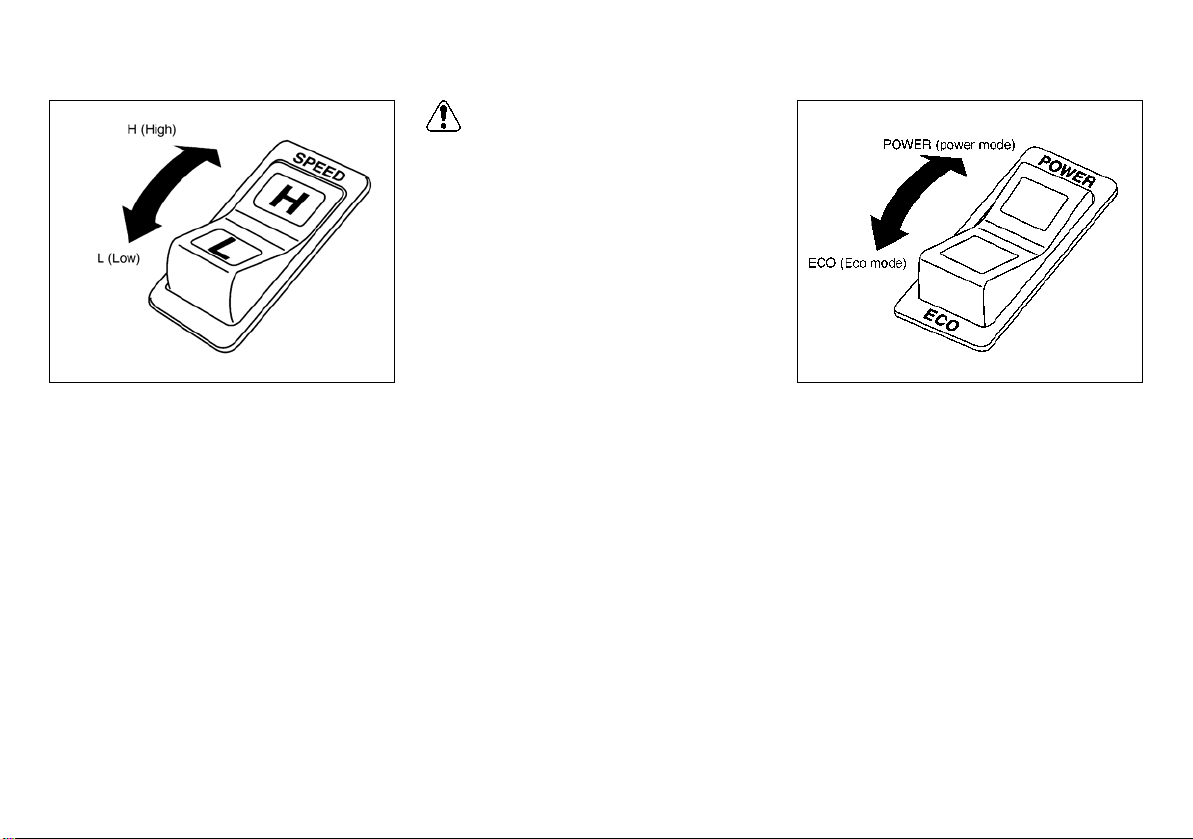
MAXIMUM SPEED CHANGE
SWITCH (option)
This switch is an optional setting switch for
electronic control gasoline vehicle and gasoline-LPG vehicle or diesel speed control vehicle. It allows you to switch the maximum speed
between H (high speed mode) and L (low
speed mode). Press the H (high) side of the
switch if there is no need to limit the maximum
speed to a low level, or press the L (Low) side
to limit the maximum speed to a low level.
The lamp on the side you pressed illuminates,
indicating the speed mode that is currently selected.
THROTTLE SENSITIVITY ADJUST
SWITCH
This switch is an optional setting switch for
electronic control gasoline vehicle and gasoline-LPG vehicle. It allows you to switch the
starting acceleration between POWER (power
mode) and ECO (economy mode). Press the
POWER side of the switch to accelerate the
forklift at a normal rate, or press the ECO side
to accelerate the forklift slowly.
The lamp on the side you depressed illuminates, indicating the power mode that is currently selected. You can switch from one mode
to the other, as described in the table.
41
Page 43

CAUTION:
WARNING:
Switching
MOM1903
operation
From POWER
to ECO
From ECO
to POWER
During
driving
Not
possible
Not
possible
During a halt
and ignition
switch OFF
Possible
Possible
NOTE:
Switching from the ECO mode to the POWER mode can be done only when the accelerator is released.
Turn the ignition switch off before changing the POWER/ECONOMY SWITCH.
FUEL-CHANGE SWITCH
(LPG - gasoline dual fuel forklift)
This switch is used to switch fuel from LPG to
gasoline or from gasoline to LPG.
LPG position: Turn to this position to use LPG.
Neutral position: Turn to this position to exhaust fuel from the fuel pipe.
Gasoline position: Turn to this position to use
gasoline.
The lamp illuminates for the fuel that is currently being used.
Do not manipulate the LPG cylinder charge
valve (green or gray), otherwise LPG may
leak out into atmosphere.
NOTE:
When the engine is running, you can
switch between fuels by operating the
switch.
To switch from one fuel to the other,
strictly follow the specified procedure after warming up the engine.
To prevent deterioration of gasoline,
drive the forklift with gasoline several kilometers about once every two weeks.
The engine does not start when the se-
lector switch is in the neutral position.
Do not forget to turn the switch to the
LPG or gasoline position before starting
the engine.
42
Page 44

CAUTION:
Do not operate the forward-reverse lever
MOM1904
MOM1905
before the forklift comes to a full stop.
When operating the lever, do it correctly
while pressing the clutch pedal flat.
Depending on the model used, the gear
shift lever may be placed on the right
side of the forward-reverse lever (optional). Before use, therefore, make sure of
the position of each lever to avoid operating the wrong lever.
FORWARD-REVERSE LEVER
(MT vehicle)
This lever is used to change the running direction of the forklift (forward or reverse). Push the
lever forward to drive forward, or pull it towards
you to back up. The neutral position is at the
midpoint.
When starting the engine, always return
the forward-reverse lever to the neutral
position.
When operating the lever while the en-
gine is running, be sure to depress the
clutch pedal flat.
GEAR SHIFT LEVER (MT vehicle)
This lever is used to shift gears between low
speed (1st speed) and high speed (2nd
speed). Push the lever forward to shift to low
gears, or pull the lever towards you to shift to
high gears. The neutral position is at the midpoint.
43
Page 45

SELECTOR LEVER (AT vehicle)
WARNING:
MOM2036
MOM1907
This lever is used to change the running direction of the forklift (forward or reverse). Push the
lever forward to drive forward, or pull the lever
towards you to back up. The neutral position is
at the midpoint.
The same operating method applies to the selector lever positioned on the right side of the
forward-reverse lever (option).
NOTE:
The engine cannot be started when the selector lever is in any position other than the
neutral position.
PARKING BRAKE LEVER
When parking the forklift, fully pull the lever towards you. To release the parking brake, push
down the button on top of the lever and then
push the lever forward.
When parking the forklift on a slope, fully pull
the lever towards you and set a chock behind
each wheel.
Always depress the brake or inching
pedal before releasing the parking brake
to avoid movement of the forklift before
selecting a direction.
Driving the forklift with the parking brake
applied could cause the brakes to fail
due to overheating. Also, it hastens
brake pad wear.
NOTE:
To remind the operator to apply the parking
brake, an alarm will sound if:
The operator leaves the operator’s seat
without applying the parking brake while
the ignition switch is in the ON position.
The operator turns off the ignition switch
without applying the parking brake,
whether or not the operator is sitting on
the operator’s seat.
44
Page 46

ACCELERATOR PEDAL
CAUTION:
WARNING:
MOM1908
MOM1909
MOM1910
This pedal allows you to adjust the rotational
speed of the engine. The engine speed changes according to the degree to which the accelerator pedal is depressed.
Do not depress the accelerator pedal
quickly. Depress it slowly to prevent a sudden or rapid start or a shift or falling of cargo.
BRAKE PEDAL
This pedal allows you to bring the forklift to a
stop or slow it down.
Do not brake the forklift too hard. Doing
so may cause the forklift to become unbalanced and could result in a serious
accident.
Adjust the braking effort according to the
cargo weight.
Do not leave your foot on the brake pedal
while driving. Doing so may cause the
brakes to fail because of overheating. Also, it hastens brake pad wear.
INCHING BRAKE PEDAL
(AT vehicle)
The inching brake pedal allows you to finely
adjust the forward and reverse running speed.
The clutch begins to slip when you slightly depress this pedal, and the clutch is completely
disengaged and the brakes are applied when
you further depress the pedal, in which case
the inching brake pedal acts in the same way
as a brake pedal.
45
Page 47

WARNING:
Do not leave your foot on the inching
CAUTION:
MOM1911
brake pedal when driving the forklift.
Doing so may cause the clutch to slip
and prevent engine braking from taking
effect. Moreover, it could cause the
brakes to fail because of overheating.
Also, doing so may cause the hydraulic
clutch in the transmission to slip and
give off a large amount of heat, causing
the clutch to overheat, wear down in a
short time or seize up in the worst case.
CLUTCH PEDAL (MT vehicle)
This pedal is used along with the forward-reverse lever or the gearshift lever.
When operating the forward-reverse lever or
the gearshift lever, depress the clutch pedal
flat, shift the forward-reverse lever or the gearshift lever from one position to another, and
then slowly take your foot off the clutch pedal.
Do not leave your foot on the clutch ped-
al when driving the forklift.
Doing so may cause the clutch to slip
and hastens the wearing away of the
clutch discs.
46
Page 48

STARTING AND OPERATING
WARNING:
WARNING:
MOM1912
GASOLINE ENGINE STARTING
(Including LPG - gasoline dual fuel
forklift)
Do not breathe exhaust gases. They con-
tain colorless and odorless carbon monoxide. Carbon monoxide is a dangerous
gas and can cause unconsciousness or
death.
Do not run the engine in closed spaces or
poorly ventilated rooms such as a garage
or refrigerator, etc.
Follow the procedure outlined below to start
the engine.
LPG - gasoline dual fuel forklifts have a fuelchange switch. Use this switch to select the
desired fuel.
When using LPG, slowly open the (red) discharge valve on LPG cylinder (tank) to start the
engine.
1. Pull the parking brake lever up as far as
possible. Move the selector lever to the
neutral position.
2. Depress the inching brake pedal as far as
it can go.
3. Remove your foot from the accelerator
pedal. Turn the starter to start the engine.
NOTE:
Do not operate the starter for more than 10
seconds. If the engine fails to start within
10 seconds, release the starter and wait for
10 seconds before attempting to start the
engine again. This allows the battery time
to recover.
4. After starting the engine, give it time to
warm up. Allow the engine to idle for 1
minute after starting. Then, press the
accelerator pedal lightly and release it. If
the surrounding temperature is high, lightly
pressing and releasing the accelerator
pedal will reduce engine speed and permit
quiet warming up. This also results in fuel
savings.
47
NOTE:
The engine is cold immediately after
starting. Do not intermittently race the
engine or run the engine at high speeds
immediately after starting.
Do not move the key to the START posi-
tion when the engine is running. Damage
to the starter motor will result.
After operation, always close the LPG
(red) discharge valve on LPG cylinder
(tank) after shutting the engine off
(down).
After operation, if the forklift is not used
for several hours or more, or during cold
weather seasons, park the forklift with
the fuel-change switch positioned on the
gasoline side. This helps to start the engine more easily the next time (LPG gasoline dual fuel forklift).
The engine speed becomes high immediately after starting. Exercise caution when
moving the forklift or handling cargo.
Inspect the condition of the LPG hose
connections and check for gas leaks
from LPG hoses and pipes before starting the engine.
In the event of LPG leakage or some other
malfunction, close the discharge valve immediately. Have the LPG system checked
at an authorized UniCarriers FORKLIFT
dealer.
Page 49

FUEL-CHANGE SWITCH
WARNING:
CAUTION:
CAUTION:
MOM1903
(LPG - gasoline dual fuel forklift)
Do not operate (turn on or open) the LPG
cylinder (tank) change (refill) valve. Opening the valve may cause LPG to leak into
the atmosphere and could cause a dangerous fire hazard.
TO CHANGE FROM LPG OPERATION
TO GASOLINE OPERATION
1. Press the fuel-change switch and change
the switch position from the LPG to the
neutral position.
2. Shut off the red or discharge valve on the
LPG cylinder side.
3. Let the engine run at idle until it stops.
4. After the engine has completely stopped,
move the fuel-change switch to the GAS
position. Restart the engine.
Directly changing over LPG to GAS without
the fuel-change switch first being positioned at the neutral position causes the remaining fuel (LPG) and gasoline to be
mixed, resulting in a poorly operating engine. Before changing over the switch position, always exhaust the remaining fuel
(LPG) by setting the switch to the neutral
position.
To change from gasoline operation to LPG operation
1. Press the fuel-change switch and change
the switch position from GAS to the neutral
position. Slightly depress the accelerator
pedal and hold it to allow the engine to
race. Continue pressing the accelerator
pedal until the engine stops.
48
2. After the engine has completely stopped,
open the red discharge valve on the
cylinder side and move the fuel-change
switch to the LPG position. Restart the
engine.
Directly changing over GAS to LPG without
the fuel-change switch first being positioned at neutral causes the remaining fuel
(gasoline) and LPG to be mixed, resulting
in a poorly operating engine. Before changing over the switch position, always exhaust the remaining fuel (gasoline) by
setting the switch to the neutral position.
NOTE:
Change over the fuel-change switch po-
sition according to the operating procedure of this switch. Otherwise, the air/
fuel ratio of fuel (mixture) is negatively
affected, making it difficult to start the
engine.
When driving an LPG-gasoline dual fuel
vehicle using LPG during the cold weather seasons, first start the engine using
gasoline and then change over to LPG
with the fuel-change switch after warming up the engine.
Page 50

Do not use the fuel-change switch to
WARNING:
MOM1915
change fuels when the engine is running.
Change fuels only after the engine has
completely stopped.
Operate the vehicle with gasoline for sev-
eral kilometers at least once every two
weeks. This will prevent gasoline deterioration.
Do not change fuels immediately after
starting the engine. Allow the engine to
warm up before changing fuels.
With the fuel-change switch set to the
neutral position, the engine cannot be
started. Before starting the engine, always change over the switch position to
LPG or gas.
Carefully follow the procedures below when
turning the engine off after LPG operation.
1. Move the fuel-change switch to the neutral
position.
2. Let the engine idle until it stops.
3. Make sure that all of the remaining LPG (in
the piping and other receptacles) has been
used. After the engine stops, turn the
ignition switch to the OFF position.
4. After completion of operation and before
storing the vehicle for an extended period,
completely close the (red) discharge valve.
Check the engine for gas leakage. Refer to
“LPG cylinder replacement” on page 112.
In the event of gas leakage, an accident,
or some other malfunctions, immediately
and completely close the discharge valve
(colored red). Have the LPG system
checked at an authorized UniCarriers
FORKLIFT dealer.
If the forklift is not used for several hours
or more after operation, park the forklift
with the fuel-change switch in the GAS
position. This helps to start the engine
more easily the next time.
DIESEL ENGINE
Starting
1. Set the parking brake lever and move the
selector lever to the neutral position.
2. Depress the inching brake pedal as far as
it can go.
3. When the ignition key is set to the ON
position, the glow plug indicator lamp on
the instrument panel illuminates, indicating
that engine preheating has started.
Keep the ignition key in the ON position until
the glow plug indicator lamp turns off (indicates completion of preheating).
49
Page 51

NOTE (QD32 engine):
Engine preheating is controlled automatically corresponding to the engine coolant
temperature, atmospheric air temperature,
etc., and the glow plug indicator lamp turns
off when the engine is preheated to the
specified temperature.
4. When the glow plug indicator lamp has
turned off, turn the ignition key to the
START position while fully depressing the
accelerator pedal, until the engine starts.
NOTE (for diesel engines only):
Do not operate the starter for more than
30 consecutive seconds.
If the engine does not start even after op-
erating the starter 3 times for approximately 5 seconds, turn the ignition key to
the OFF position and then wait for about
30 seconds. Subsequently, try to start it
again from the preheating process.
5. After the engine has started, release the
accelerator pedal gradually and then
perform warm-up of engine.
NOTE:
When restarting, return the ignition key
to the OFF position once, and then turn it
to the START position.
Regardless of the atmospheric tempera-
ture, always perform warm-up for approximately 5 minutes. During warm-up,
check for any malfunction of meters,
warning lights or indicator lamps.
Failure to properly warm up the engine
can cause degradation and shortened
life of engine.
When it is not necessary to preheat the
engine because of high engine coolant
temperature immediately after it stops or
for some other reasons, the engine can
be started by turning the ignition switch
to the START position before the glow
plug indicator lamp turns off.
If the glow plug indicator lamp is not illu-
minated, malfunction may exist. In this
case, promptly contact your supervisor
for measures or contact an authorized
UniCarriers FORKLIFT dealer to inspect
the forklift.
Stopping
To stop the engine, turn the ignition key to the
OFF position.
50
Page 52

CAUTION:
3. When the gear shift is positioned in the
CAUTION:
MOM1916
MOM1917
desired place, foot the accelerator pedal
while gradually releasing the clutch pedal.
Positioning the gear shift in 1st without decelerating the forklift may cause a gear
shift shock, resulting in dropped loads or
damaged transmission.
GEARSHIFT LEVER
MT vehicle
FORWARD-REVERSE
lever and GEARSHIFT lever
The “FORWARD-REVERSE” lever is used to
make a directional change.
1. Release the accelerator pedal.
2. Foot the brake pedal, to fully depress the
clutch pedal immediately before the forklift
stops.
3. Further depress the brake pedal, to
completely stop the forklift.
4. When the forklift completely stops, position
the forward-reverse lever in forward or
reverse.
While the forklift is moving, do not change
over the forward-reverse lever positions.
Otherwise, the transmission may be damaged.
The “GEARSHIFT” lever permits selection of
different transmission gear ratios.
1. Simultaneously with the release of
accelerator pedal, fully depress the clutch
pedal.
2. Change the gear shift from 1st to 2nd or
from 2nd to 1st.
51
Page 53

AUTOMATIC TRANSMISSION
WARNING:
CAUTION:
MOM1918
MODELS
Automatic transmission models do not
have the creeping phenomena.
The forklift does not move regardless of
whether accelerator is depressed or not.
When the selector lever is in the F
(forward) or R (reverse) position:
The forklift starts moving when the
accelerator pedal is depressed.
The forklift does not move if the
accelerator pedal is not depressed.
2. While driving the forklift
When the selector lever is in the F or R
position:
The forklift continues accelerating by
depressing the accelerator pedal.
When the accelerator pedal is released.
The engine brake is applied with the
clutch engaged if the forklift speed is
above 6.5 km/h (4.5 MPH) for 3 seconds.
3. Inhibitor function
When the selector lever is in the F
(forward) or R (reverse) position, it is not
possible to start the engine.
4. Precautions
This forklift has no creeping
phenomena.
The forklift will not move if the selector
lever is in the F or R position unless you
depress the accelerator pedal. When
depressing the accelerator pedal, be
sure to visually confirm the position of
the selector lever.
When starting on slopes, be sure to
apply the parking brake to hold the
forklift and then start, even if the slopes
are gentle.
Avoid rapid acceleration (especially
when carrying a high load).
While the forklift is moving, do not change
over the selector lever positions. Otherwise, the transmission may be damaged.
1. When starting the forklift from the stopped
condition
When the selector lever is in the neutral
position:
The clutch disengages to the neutral position if the forklift speed is below 6.5 km/h
(4.5 MPH) for 3 seconds.
When the selector lever is in the neutral
position:
The lever is in the neutral position
independent of the forklift speed.
52
Page 54

PARKING BRAKE LEVER
WARNING:
WARNING:
MOM1919
MOM1920
To set the brake, pull the parking brake lever
backward. To release the brake, press the button and then push the parking brake lever forward. Before leaving the forklift, be sure to
apply the parking brake securely.
Always depress the brake or inching pedal
before releasing the parking brake to avoid
movement of the forklift before selecting a
direction.
INCHING BRAKE PEDAL
1. Fully depress the inching brake pedal.
2. Move the selector lever to the forward or
reverse position.
3. Depress the accelerator pedal little by little.
At the same time, gradually releasing the
inching brake pedal moves the forklift bit
by bit.
When the inching/brake pedal is fully de-
pressed the service brake will be applied.
However the inching/brake pedal should
not be used as the method for stopping
the forklift. In normal traveling operations, the inching/brake pedal should
only be used during loading, or unloading, which requires short, controlled
movement of the forklift.
During deceleration on any grade, only
use the brake pedal or an increase or decrease in speed by using the accelerator.
Do not use or depress the inching pedal
because this would put the transmission
in the neutral mode.
53
Page 55

LOAD CONTROL LEVERS
WARNING:
WARNING:
MOM1921
To control the loading mechanism for moving
the fork up and down and tilting the mast forward and backward, there are two operating
methods: 2-lever type or 1-lever type.
Before using the forklift, make sure which operating lever type is adopted in controlling the
loading mechanism and thoroughly read the
related instruction manual.
Always sit in the operator’s seat when
operating the lever.
Operating the control lever without prop-
erly sitting on the operator’s seat causes
the loading interlock warning lamp to
blink and the loading mechanism to be
inactive.
Before operating the lever, make certain
that the surrounding area is clear and it is
safe to proceed.
If the engine is stopped, operation of the
lever to the downside or lowering direction may cause the fork and mast to go
down due to its own weight or the cargo
that may be on the forks. This may result
in serious damage or injury.
Always avoid any abrupt or sudden lever
operation that may cause loads to shift
or fall off fork or cause the forklift to become unbalanced and tip over.
2-lever type
This method uses 2 levers: a lift lever for moving the fork up and down and a tilt lever for tilting the mast forward and backward:
Lift lever:
Lift: Pull the lever to the operator side.
Lower: Push the lever forward.
54
Tilt lever:
Forward: Push the lever forward.
Backward: Pull the lever to the operator side.
Do not perform forward tilt while raising
the forks, as this may cause loads to shift
or fall, which could affect the stability of
the forklift.
Do not perform forward tilt while lifting
loads in higher positions. This may
cause loads to shift or fall, which could
affect the stability of the forklift.
NOTE:
Control of lifting speed:
Can be changed by controlling the tilt angle of the lever and by how much the operator depresses the accelerator pedal.
Control of lowering speed:
Can be changed only by controlling the
tilt angle of lever. Do not depress the accelerator pedal.
Control of forward and backward tilting
speeds:
For both forward and backward tilts, the
speed can be changed by controlling the
tilt angle of the lever and by how much
the operator depresses the accelerator
pedal.
Page 56

1-lever type
WARNING:
MOM1922
Forward: Push the lever in the left
forward direction.
Backward: Diagonally pull the lever to the
right side of the operator.
Simultaneous operations are also allowed by
combining up and down movements and forward and backward tilts.
This may be done by moving the lever into the
a, b or c position.
a: Backward tilt while lifting:
Pull the lever to the center of the operator
side.
b: Backward tilt while lowering:
Turn over the lever to the right side of the
center.
c: Forward tilt while lowering:
Push the lever in the center forward
direction.
NOTE:
Control of lifting, forward tilting and
backward tilting speeds:
Can be changed by controlling the tilt angle of the lever and by how much the operator depresses the accelerator pedal.
Control of lowering speed:
Can be changed only by controlling the
tilt angle of the lever. Do not depress the
accelerator pedal.
This method performs up and down movements of the fork and forward and backward
tilting of mast using 1 lever:
Lift: Diagonally pull the lever to the
left side of the operator.
Lower: Push the lever in the right
forward direction.
Do not perform forward tilt while raising the
forks, because this may cause loads to shift
or fall, which could affect the stability of the
forklift.
55
Page 57

CAUTION:
MOM1923
Loading
condition
Without load
With load
Forward tilt operation of mast
Automatically stops in the
horizontal fork position.
• No automatic forward stop to
horizontal
• No movement when turning
on the tilt-horizontal switch
NOTE:
In case of 2-lever method, the tilt-hori-
zontal switch is attached to the tilt lever.
The tilt-horizontal switch is kept on while
pressed and turned off when released.
Unless the tilt-horizontal switch is
pressed, normal forward and backward
tilt operations are performed.
TILT-HORIZONTAL SWITCH
(option)
When forward tilt is performed with the mast
tilted backward, the forward tilt operation can
automatically be stopped in the position where
the fork is level.
Performing forward tilt while pressing the tilthorizontal switch moves the mast as shown in
the following list, depending on the loading
condition.
With load: Turning on the tilt-horizontal switch
during operation will not automatically stop tilt
in the horizontal direction (no movement).
56
The horizontal fork position allowing automatic stops requires a position parallel to
the road surface. Do not use this function if
the road surface is not level.
Page 58

JOYSTICK CONTROL LEVER TYPE
WARNING:
MOM2040
MOM2041
MOM2377
(option) (2 ton, 2W MAST only)
The joystick lever is an electrically controlled type.
The cargo handling operation can be performed
only when the ignition switch is turned on.
Do not perform forward tilt while raising the
forks. Otherwise, dropped loads or an unbalanced forklift may cause the forklift to
fall down.
NOTE:
Before the ignition switch is turned on,
make sure that the joystick lever is set to
the neutral position. If the lever is placed
in any position other than the neutral position, cargo handling or fork operation
cannot be performed.
When the ignition switch is turned off,
the fork does not lower even under its
own weight.
The joystick lever is used to tilt the mast
forward or backward and to lift or lower
the forks. Cargo handling speed (lift, lower, forward and backward) can be adjusted by the distance that the lever is
moved.
For detailed joystick lever operation, re-
fer to the illustration above.
57
Page 59

WARNING:
The warning mark and a malfunction
WARNING:
MOM2378
MOM2218
MOM2043
message will appear on the meter when the
joystick control system malfunctions. When
this occurs, immediately stop cargo handling
operations and have the forklift checked and
repaired by an authorized UniCarriers FORKLIFT dealer.
If an erroneous cargo handling operation is
noticed regardless of the joystick lever position, press the emergency stop button on
the console box, stop cargo handling operations and have the forklift checked and repaired by an authorized UniCarriers
FORKLIFT dealer. (To release the emergency stop button, turn it in the direction indicated by the arrow.)
58
Page 60

TRAVELING
WARNING:
WARNING:
CLIMBING
While traveling, the mast should be tilted back
and the forks lowered to approximately 200 mm
(8 in) above the ground.
1F1/1F2 models do not have the creeping
phenomena.
The forklift will not move if the selector
lever is in the F or R position unless the
operator depresses the accelerator pedal. When depressing the accelerator pedal, be sure to visually confirm the
position of the selector lever.
When starting on slopes, be sure to ap-
ply the parking brake to hold the forklift
and then start, even if the slopes are gentle.
Avoid rapid acceleration (especially
when carrying a high load).
TURNING
The smaller the radius of a turn to be made,
the lower the speed of the forklift should be.
When making a sharp turn, always drive the
forklift at a low speed.
Because the movement of a forklift is dif-
ferent from that of a passenger vehicle,
always reduce speed while making turns
to ensure that the forks and counterweight will clear objects during the turn.
Turning at a high speed could result in
loss of control and a potential lateral tipover.
Do not make a turn with the fork lifted
high or at a high speed. This could result
in a loss of control and potential tip-over.
For safety reasons, when driving a loaded
forklift up a steep grade, it must be driven forward with the load in front; on a downgrade,
backward, with the load behind.
On a UniCarriers FORKLIFT equipped with an
automatic transmission, standing starts and
stopping on a slope can be accomplished by
manipulating the accelerator and brake pedals
as required.
For stopping, the brake pedal should be used
at all times.
For traveling, depress the accelerator pedal.
To make a standing start on a slope, the parking brake can be used instead of the brake
pedal.
59
Page 61

STOPPING AND PARKING
WARNING:
WARNING:
MOM1926
To stop the forklift, remove your foot from the
accelerator pedal and depress the brake pedal.
Do not make sudden stops because the
forklift may pitch forward and drop the
load.
When leaving the forklift, set the parking
brake, adjust the mast to an upright position, lower the forks until they rest on the
ground and turn off the ignition switch.
NOTE:
If the operator leaves the operator’s seat
without pulling the parking brake lever,
the warning buzzer alerts the operator.
If the operator is more than 7.6 m (25 ft)
from the forklift or moves out of sight of
the forklift, the key should be removed.
Forks should be inspected daily for any
damage, bending or other malfunctions.
Report any conditions to your supervisor.
FORKS
The fork-to-fork distance can be properly adjusted by unlocking the lock pins on the forks.
These pins are unlocked by pulling them up
and turning them 90° in either direction. Forks
must be equally located from the center of the
forklift. After the correct fork-to-fork distance is
obtained, secure the forks with the lock pins.
NOTE:
Various kinds of forks are available depending on the lifting capacity. Select the
proper forks so that the specifications
stamped on the side face of them will meet
the lifting capacity of your forklift. Do not
use forks with specifications that are below
the lifting capacity of your forklift.
60
Page 62

LOADING AND UNLOADING
LOADING
Adjust the distance between the forks so that
they are at or near the same distance from the
centerline of the forklift. The wider the interval
between forks, the better the balance. Be sure
to apply the fork latches after setting the forks.
(Refer to page 60.)
Approach slowly, straight toward the load, and
stop just in front of it. Adjust the mast to the
vertical position, matching the height of the
forks to the position of the pallet. Advance
slowly and completely insert forks beneath the
load. Set the selector lever to the neutral position and apply the parking brake. Then raise
the load. Confirm that the load is stable and tilt
it backward. Release the parking brake and
back up the forklift slowly.
TRANSPORTATION
When transporting loads, the forklift should be
driven carefully at a slow speed with the load
kept low and tilted back. When the load is big
enough to block forward visibility, drive the
forklift backward. Follow the safety rules.
UNLOADING
Slowly approach the unloading site and stop
facing straight ahead.
Move the selector lever into the neutral position and apply the parking brake. After adjusting the mast to the vertical position, raise the
load a little above the stack on which it is to be
placed. Release the parking brake and advance slowly into the proper position for stowing. Apply the parking brake and place the
selector lever in the neutral position.
Slowly lower the forks to set down the load. After moving the selector lever to the reverse position, release the parking brake and back up
the forklift until the forks separate completely
from the load.
61
Page 63

LIFTING UP FORKLIFT
WARNING:
MOM1034
WARNING:
Make sure that the wire ropes do not in-
terfere with the overhead guard while
lifting the forklift.
Make sure that the wire ropes and lifting
device are strong enough to support the
forklift safely, because the forklift is extremely heavy.
Do not use the cab frame (overhead
guard) to lift up the forklift.
Do not get under the forklift while lifting
the forklift.
Only use this method as a last resort to
move the forklift if the normal work application requires repeated lifting. Permanent
lifting devices must be mounted on the
forklift by UniCarriers Corporation. Contact
an authorized UniCarriers FORKLIFT dealer for more details.
When lifting the entire forklift, secure wire
ropes to the holes located on both sides of the
outer mast cross beam and to the hook on the
counterweight, and then utilize a lifting device.
62
Page 64

This illustration shows the sling point of the at-
MOM2356
MOM2619
tachments which are possible to be installed
and removed.
FUNCTION TESTS
The functional tests are performed to check
whether the forklift functions correctly after it
has been transported (over land or water), or
after it has been taken out of storage.
The test covers the following items, but since exclusive tools and equipment are required for Items
1 and 2, request that an authorized UniCarriers
FORKLIFT dealer perform the test.
Items
1. Those that are indicated in daily care.
2. Dynamic tests
2-1) Mobility (traveling and maneuvering) test
Make sure that the forklift moves in the direction specified by the selector lever, and that the
forklift operates correctly when the parking
brake lever is locked or released. Also check to
make sure that the steering feels normal and
that it operates satisfactorily.
Elevate and lower test load.
2-2) Stacking test
Raise the test load to the maximum height of
the mast and lower at the maximum speed,
stopping the descent several times, to make
sure that it stops smoothly.
63
Page 65

2-3) Lowering speed test
WARNING:
CAUTION:
MOM2620
Check to make sure that the maximum lowering speed does not exceed 0.6 m/s (2.0 ft/s)
(by measuring the speed).
3. Test for holding load
Check the rate at which the mast lowers naturally [100 mm (3.94 in)/10 min max].
Check the rate at which the tilt cylinder tilts forwards naturally (5 degrees/10 min max).
TRACTION BAR
Use the traction bar only when required to assist in pulling or dragging the forklift from a
ditch or from being stuck.
Always ensure that the traction bar is ful-
ly inserted until the stopper touches
against the counterweight. This will reduce the possibility of the bar slipping.
The traction bar is not a towing or draw-
ing pin or coupling, and it should only be
used for assistance in that type of operation.
When using wire, cables or chains to pull
or drag an object, ensure that all items
are in good condition and are not damaged.
Always gently draw towing cables or
chains so as not to cause any shock,
abrupt movements which could cause
the traction bar to slip, bend or damage.
If the traction bar or towing device slips,
pulls out or becomes damaged, stop the
towing operation and replace damaged
parts or discontinue that type of operation.
Never use the traction bar for towing the
forklift or other vehicles.
64
Page 66

SEAT (EXCEPT FOR EU REGION)
WARNING:
MOM1927
MOM1929
SEAT ADJUSTMENT
Forward and backward control lever
The forward and backward control lever is located at the front of the seat slider.
To adjust the seat position, pull the lever upward and hold it there while sliding the seat forward or backward to the desired position.
Release the lever to lock the seat.
Before operating the forklift, be sure that the
seat is locked securely.
Before adjusting the seat, turn the igni-
tion key off.
Be sure to adjust the seat position while
the forklift is stationary.
Suspension seat operator’s weight
adjustment
Adjust the suspension seat to the operator’s
weight by turning the weight adjustment dial at
the front right side of the seat.
Optimum fine adjustment for operating surface
conditions is also possible.
65
Page 67

Backrest inclination adjustment
WARNING:
MOM1928
MOM1930
Adjust the backrest to the desired angle while
pulling the lever located to the left of the seat.
Release the lever to lock the backrest.
Do not excessively tilt back the backrest,
otherwise the seat belt may not demonstrate its performance in an emergency.
When adjusting the angle of the back-
rest, gently do it while holding the backrest by hand. Hasty and rough
adjustment may cause an injury, for instance the back of the seat may bump
against the operator’s face and body, or
the operator’s finger may get caught between the backrest and the grip.
NOTE:
The backrest can be tilted forward de-
pending on the situation.
The tilting manner is the same as tilting
backward, but it cannot be fixed at an optional position.
A seat pocket and magazine rack are on
the back side of the backrest.
66
Seat belt
1. Holding the tongue, pull out the seat belt
gently.
2. Wrap the lower part of the hipbone with the
seat belt as tight as possible.
NOTE:
If the seat belt cannot be pulled out because it is locked, loosen it once and pull it
out once more.
3. Being careful not to twist the seat belt,
insert the tongue into the buckle until it
clicks.
To unfasten the seat belt, press the button
on the buckle and pull the tongue out of it.
While lightly holding the tongue, let the
seat belt be rewound gently.
Page 68

NOTE:
WARNING:
When unfastening the seat belt, be sure to
hold the tongue because the tongue may be
rapidly pulled together with the seat belt.
Check the seat belt condition for the fol-
lowing points.
- Cut or frayed strap
- Worn of damaged hardware including
anchor points
- Buckle or retractor malfunction/Loose
stitching
Tightly wrap the seat belt around the hip-
bone as low as possible. If the seat belt
comes off the hipbone and it wraps
around the abdomen, it may cause an injury because strong pressure is applied
onto the abdomen.
Do not fasten the seat belt if it is twisted.
If it is twisted, it may cause an injury because the twisted belt cannot disperse
an impact and a limited part is shocked
intensively.
Do not adjust the seat belt to be loose
such as slackening it intentionally by use
of a clip. If the seat belt is fastened loosely, it cannot function to its full performance.
Do not excessively tilt back the backrest,
otherwise the seat belt may not function
to its full performance.
Do not put any foreign substance into the
buckle or belt winder, otherwise it cannot
function to its full performance because
it cannot be fastened normally.
If the seat belt is used by a pregnant
woman or sick person, consult with a
doctor beforehand because her/his abdomen is pressed by the seat belt.
A seat belt that has been impacted, dam-
aged or broken in part may not function
to its original performance. Replace it
with a new one at an authorized
UniCarriers FORKLIFT dealer.
For cleaning the seat belt, use a neutral
detergent or lukewarm water. After cleaning, dry it completely before use. Be sure
not to use an organic solvent such as
benzine or gasoline, otherwise the seat
belt deteriorates in its performance and
may not function as designed.
UniCarriers Corporation recommends that
injured persons use seat belts. Check with
your doctor for specific recommendations.
Periodically check to see that the seat
belt and metal components, such as
buckles, tongues, retractors, flexible
wires and anchors, work properly. If
loose parts, deterioration, cuts or other
67
damage on the webbing is found, the entire seat belt assembly should be replaced.
Page 69

SEAT (FOR EU REGION)
WARNING:
MOM2045
MOM2046
Before adjusting the seat, turn the igni-
tion switch to the OFF position.
Be sure to adjust the seat position while
the forklift is stationary.
SEAT ADJUSTMENT
Forward and backwards control lever
The forward and backwards control lever is located at the front of the seat slider.
To adjust the seat position, pull the lever upward and hold it there while sliding the seat forward or backward to the desired position.
Release the lever to lock the seat.
Before operating the forklift, be sure the seat is
locked securely.
Suspension seat operator’s weight
adjustment
Adjust the suspension seat to the operator’s
weight by turning the weight adjustment dial at
the front right side of the seat.
Optimum fine adjustment for operating surface
conditions is also possible.
68
Page 70

Backrest inclination adjustment
WARNING:
MOM2047
Adjust the backrest to the desired angle while
pulling the lever located to the right of the seat.
Release the lever to lock the backrest.
Do not excessively tilt back the backrest,
otherwise the seat belt may not demonstrate its performance in an emergency.
When adjusting the angle of the backrest,
gently do it while holding the backrest by
hand. Hasty and rough adjustment may
cause an injury, for instance the back of
the seat may bump against the operator’s
face and body, or the operator’s finger
may get caught between the backrest and
the grip.
NOTE:
The backrest can be tilted forward de-
pending on the situation.
The tilting manner is the same as tilting
backward, but it cannot be fixed at an optional position.
There is a seat pocket for the operators
manual, maintenance manual and other
documents on the rear side of the backrest.
69
Page 71

SEAT BELT
WARNING:
MOM2048
1. Holding the tongue pull out the seat belt
gently.
2. Wrap the lower part of the hipbone with the
seat belt as tight as possible so as not to
get loose.
NOTE:
If the seat belt cannot be pulled out because it is locked, loosen it once and pull it
out once more.
3. Being careful not to twist the seat belt, insert
the tongue into the buckle until it “clicks”.
For unfastening the seat belt, press the button on the buckle and pull the tongue out of
it. While lightly holding the tongue, let the
seat belt be rewound gently.
NOTE:
When unfastening the seat belt, be sure to
hold the tongue because the tongue may be
pulled rapidly together with the seat belt.
Check the seat belt condition for the fol-
lowing points.
- Cut or frayed strap
- Worn of damaged hardware including
anchor points
- Buckle or retractor malfunction/Loose
stitching
Tightly wrap the seat belt around the hip-
bone as low as possible. If the seat belt
comes off the hipbone and it wraps
around the abdomen, it may cause an injury because strong pressure is applied
onto the abdomen.
Do not fasten the seat belt as it is twisted.
If it is twisted, it may cause an injury because the twisted belt cannot disperse
an impact and a limited part is shocked
intensively.
Do not adjust the seat belt to be loose
such as slackening it intentionally by use
of a clip. If the seat belt is fastened loosely, it cannot demonstrate its performance.
Do not excessively tilt back the backrest,
otherwise the seat belt may not demonstrate its performance.
70
Do not put any foreign substance into the
buckle or belt winder, otherwise its performance cannot be demonstrated because it cannot be fastened normally.
If the seat belt is used by a pregnant
woman or sick person, consult with the
doctor beforehand because her/his abdomen is pressed by the seat belt.
The seat belt that was once impacted,
damaged or broken in part may not demonstrate its original performance. Replace it with a new one at the nearest
UniCarriers FORKLIFT dealer.
For cleaning the seat belt, use a neutral
detergent or lukewarm water. After cleaning, dry it completely before use. Be sure
not to use an organic solvent such as
benzine or gasoline, otherwise the seat
belt deteriorates in its performance and
may not function as designed.
UniCarriers Corporation recommends that
injured persons use seat belts. Check with
your doctor for specific recommendations.
Periodically check to see that the seat belt
and metal components, such as buckles,
tongues, retractors, flexible wires and anchors, work properly. If loose parts, deterioration, cuts or other damage on the
webbing is found, the entire seat belt assembly should be replaced.
Page 72

WARNING:
Open operation
WARNING:
MOM1934
Close operation
TOP PANEL
The top panel can be opened toward the rear
of the forklift.
The top panel is automatically retained by
the gas stay.
1. Tilt the steering wheel all the way forward
and upward. Use the service release latch
(yellow) lever. Refer to page 75.
• For LPG & dual fuel units with swing down
or out LPG tank mounting, you must swing
out (down) the LPG tank before opening
the top panel.
• For forklift equipped with joystick
To open top panel
Before the top panel is opened, tilt the joystick control unit.
2. Pull the lever on the left side of the
operator’s seat upward to tilt the backrest
forward.
3. Push the lever in the front left side of the
top panel upward to unlock the top panel,
and lift the top panel rearward while
pushing the lever.
NOTE:
For opening the top panel rearward, refer
to the Top Panel Open Procedure Label
on the body.
Before opening the top panel, swing-
open the LPG cylinder as illustrated later
in this section.
1. Make sure that the steering wheel is leapt
up.
2. Depress the top panel. Since there is
reaction of the gas stay, depress the top
panel while pressing its front top until it is
completely locked.
3. Raise the backrest of the operator’s seat
up to the original position.
4. Pull the steering wheel toward the
operator’s side to the limit so that it is
locked.
• For forklift equipped with joystick
To close top panel
Return the joystick control unit to the original position.
To avoid pinching your fingers, always
grasp the handle when closing the top
panel.
On forklifts equipped with a top panel
lock, make sure the top panel is securely
locked.
71
Page 73

TOP PANEL LOCK
WARNING:
MOM2239
Do not open the top panel with the engine
running. Do not place hands near the cooling fan because it rotates at a high speed
and may cause injury. When opening the
hood, be sure to turn off the engine. When
starting the engine, check the hood to
make sure that it is locked.
The forklift is provided with a top panel lock to
ensure that the engine hood cannot be opened
unless the lock is canceled.
72
Page 74

WARNING:
WARNING:
MOM2359
4. If the light is illuminated, turn the key off
and check that the swing mount is
secured and locked.
5. Check to see if the switch is damaged.
WARNING:
Only authorized UniCarriers FORKLIFT
service technicians should perform repair
and/or adjustment to the switch or latch.
Refer to pages 111 to 126 for additional information on the LPG - gasoline dual fuel
forklift.
Top panel closing procedure:
1. Make sure that the steering wheel is tilted
upward.
2. By pressing on the front of top panel,
completely close until latched.
3. Raise the backrest of the operator’s seat
up to the original position.
4. Pull the steering wheel toward the
operator’s seat to the limit so that it is
locked.
WARNING:
Keep fingers clear when closing the top
panel.
On forklifts equipped with a top panel
lock, make sure that the top panel is securely locked.
LPG CYLINDER HOLDER OPENING
PROCEDURE
1. Pull out the latch pin to unlock the LPG
cylinder holder. Slowly open the LPG
cylinder holder.
2. Insert the lock pin into the lock pin hole.
3. Perform the top panel opening procedure.
Before opening the top panel, make sure
that the lock pin is properly inserted into
the lock pin hole.
LPG CYLINDER HOLDER CLOSING
PROCEDURE
Before closing the LPG cylinder holder, make
sure that the top panel is properly closed.
1. Pull out the lock pin. Slowly close the LPG
cylinder holder, and then lock with the latch
pin.
Make sure that the latch pin is properly
locked.
2. While seated in the operator’s seat, turn
the ignition switch on.
3. Check to make sure that the cylinder lock
indicator light is off.
73
Page 75

WARNING:
Before adjusting the steering wheel, turn
MOM1935
MOM1931
the ignition switch off and set the parking
brake.
Be sure to adjust the steering wheel po-
sition while the forklift is stationary.
After adjustment, try to move the steer-
ing wheel upward or downward to ensure
that it is locked securely.
RADIATOR COVER
The radiator cover can be removed with the
top panel closed.
For inspection of the radiator or replenishment
of the engine coolant (cooling water), loosen
the right and left bolts by hand.
NOTE:
Be absolutely sure to hand tighten the
bolts when reinstalling the radiator cover.
Refer to page 83 for information on the
engine coolant level check procedure.
STEERING WHEEL
Tilt adjustment
The position of the steering wheel can be adjusted. To adjust, push down on the tilt lever
(black) located on the left side of the steering
column, and move the wheel to the desired position. After selecting the wheel position, pull
up on the lever fully to lock it in place.
74
Page 76

WARNING:
Before starting the engine, make sure
WARNING:
MOM2360
MOM1933
that the steering wheel is returned to the
original locked position.
Do not operate the forklift with the steer-
ing wheel in the service release position.
Doing so could result in an accident.
NOTE:
The steering wheel position adjusted by
the tilt mechanism does not vary when it is
tilted.
SERVICE RELEASE LATCH
Press the steering wheel forward while depressing the service release latch on the left
side under the steering wheel, and the steering
wheel tilts forward.
For returning the steering wheel to the original
position, pull it toward the operator’s seat to
the limit. The service release latch returns to
the original position and the steering wheel is
locked automatically.
REARVIEW MIRROR
Adjust the right and left rearview mirrors respectively by hand so that both ensure the
best view to the rear.
Never use only the rearview mirrors for operating the forklift in reverse due to limited
visibility. Always turn and look in the direction of travel before proceeding.
75
Page 77

PRECAUTIONS FOR COLD AND
WARNING:
HOT WEATHER
In cold weather
Oil and grease
Use engine oil and grease that are suitable for
the ambient temperature. Refer to “RECOMMENDED LUBRICANTS” on page 96.
Coolant
When coolant might freeze at a low ambient
temperature, drain out the coolant completely.
In such cold weather, a recommended 50/50
mix of antifreeze solution only should be put
into the cooling system.
Antifreeze:
[Example]
Antifreeze
Coolant
capacity
5.0 liters
(4-3/8 Imp qt,
5-1/4 US qt)
0.8 liter
(3/4 Imp qt,
7/8 US qt)
–7°C
(19°F)
1.7 liters
(1-1/2
Imp qt,
1-3/4 US qt)
–18°C
(0°F)
2.5 liters
(2-1/4
Imp qt,
2-5/8 US qt)
–35°C
(–31°F)
COOLING SYSTEM BLEEDING
INSTRUCTIONS
Never remove the radiator cap when the
engine is hot. Serious burns could be
caused by high-pressure fluid or steam
escaping from the radiator.
Always ensure that the coolant is cooled
down sufficiently before removing the radiator cap. When opening the radiator
cap, wrap the cap with a shop cloth and
turn the cap slowly to release the internal
pressure.
NOTE:
Use only Genuine Long-Life Coolant
(LLC) with the proper mixture ratio for
the working environment that the forklift
will be used in.
Engine coolant must be disposed of
properly. Check your local regulations.
1. Remove the radiator cover and open the
engine hood. Remove the radiator cap.
2. Place an appropriate size container under
the radiator. Open the drain cock of the
radiator and extract the coolant.
3. After draining all of the coolant, securely
close the drain cock.
4. Prepare coolant mixture referring to the
antifreeze coolant capacity table.
5. With the radiator cap removed, locate the
engine coolant system bleeder screw. The
bleeder screw location varies depending
on the model of the engine. This screw will
either be located in the thermostat housing
or on the top of the water pump. Refer to
the following illustrations for the location of
the bleeder screw.
76
Page 78

6. Completely remove the bleeder screw, and
MOM2340
MOM2341
MOM2361
pay close attention to the sealing washer
so that it does not fall off the screw as it is
being removed.
7. Add the recommended engine coolant
mixture into the radiator, when the engine
coolant comes out of the bleeder hole with
no air bubbles. Install the bleeder screw
and tighten to 6.3 to 8.0 Nm (55.7 to 75.8
in lbs) of torque.
8. Also add coolant to the reservoir tank up to
the full line.
9. With the radiator cap removed, start the
engine and accelerate above idle RPM to
purge the air out of the LP vaporizer.
Continue to operate the engine until the
thermostat opens and you can visually see
the coolant moving in the radiator.
10. Top off the coolant (approximately 25 mm
(1 in) from the top of the radiator) in the
radiator after all air has been purged.
11. Securely attach the radiator cap.
12. Turn off the engine.
13. Close the engine hood and install the
radiator cover.
14. Start the engine, check for leaks and
ensure that the engine temperature stays
within the operating range. If the unit starts
to overheat, there is still air in the cooling
system. Repeat steps 5 to 14.
77
Battery
The battery should not be left in the discharged
state. When battery performance becomes
questionable, check the specific gravity of the
electrolyte, terminals of battery and alternator.
The normal specific gravity is 1.260 as corrected at 20°C (68°F). It changes about 0.0007 for
every 1°C (1.8°F). If the specific gravity of the
electrolyte does not indicate the correct value,
charge the battery soon.
Page 79

PROCEDURE FOR JUMP
WARNING:
CAUTION:
CAUTION:
WARNING:
MOM2117
STARTING ECCS ENGINES
6. Keep the engine speed of the booster
forklift at about 2,000 rpm, and start the
engine of the forklift being jump started.
Always follow the instructions below. Failure to do so could result in damage to the
charging system and cause personal injury.
1. If the booster battery is in another forklift,
position the two forklifts to bring their
batteries near each other.
Do not allow the two forklifts to touch.
2. Apply the parking brake. Shift the
transmission into the N (Neutral) position.
Switch off all unnecessary electrical
systems (lights, etc.).
3. Remove the vent caps on the battery (if so
equipped). Cover the battery with an old
cloth to reduce explosion hazard.
4. Connect jumper cables in the sequence
illustrated ( , , , ).
Always connect positive (+) to positive
(+) and negative (–) to body ground (for
example, strut mounting bolt, engine lift
bracket, etc.) not to the battery.
Never use a booster battery or source of
greater voltage, or it could damage engine electrical compounds.
Make sure that the jumper cables do not
touch moving parts in the engine compartment and that the cable clamps do
not contact any other metal.
5. Start the engine of the booster forklift and
let it run for a few minutes.
Do not keep the starter motor engaged for
more than 10 seconds. If the engine does
not start right away, turn the key switch off
and wait 3 to 4 seconds before trying again.
7. After starting the engine, carefully
disconnect the negative cable and then the
positive cable.
8. Replace the vent caps (if so equipped). Be
sure to dispose of the cloth used to cover
the vent holes as it may be contaminated
with corrosive acid.
9. To start the engine with a booster battery,
the following instructions and precautions
must be followed.
If done incorrectly, jump starting can
lead to a battery explosion, resulting in
severe injury or death. It could also damage your forklift. Explosive hydrogen gas
is always present in the vicinity of the
battery. Keep all sparks and flames away
from the battery.
78
Page 80

Do not allow battery fluid to come into
contact with eyes, skin, clothing or painted surfaces. Battery fluid is a corrosive
sulfuric acid solution that can cause severe burns. If the fluid comes into contact with anything, immediately flush the
contacted area with water.
Keep the battery out of the reach of chil-
dren.
The booster battery must be rated at 12
volts. Use of an improperly rated battery
can damage the forklift.
Whenever working on or near a battery,
always wear suitable eye protectors (for
example, goggles or industrial safety
spectacles) and remove rings, metal
bands or any other jewelry. Do not lean
over the battery when jump starting.
Do not attempt to jump start a frozen bat-
tery. It could explode and cause serious
injury.
Your forklift has an automatic engine
cooling fan. It could turn on at any time.
Keep hands and other objects away from
it.
IN HOT WEATHER
Oil
Engine oil should be changed to summer type
oil (recommended lubricants).
Coolant
Because the engine is more likely to overheat
in hot weather, the forklift should be parked in
a shaded area. Overheating sometimes is
caused by old, worn or cracked hoses, connections, loosened radiator cap, or old, worn
or cracked fan belt. Carefully check the cooling
system to maintain the best cooling effect.
Battery
Because the battery electrolyte evaporates in
hot weather, it is necessary to refill the battery
with distilled water. (Refer to page 86.)
79
Page 81

DAILY CARE AND INSPECTION
WARNING:
WARNING:
Do not open the top panel with the engine
running. Do not place hands near the cooling fan because it rotates at a high speed
and may cause injury. When opening the
hood, be sure to turn off the engine. When
starting the engine, check the hood to
make sure that it is locked.
To keep your forklift in the proper condition,
ready for safe operation, be sure to perform
the daily checks indicated below.
If you note any malfunction, notify your supervisor or an authorized UniCarriers
FORKLIFT dealer.
Do not operate the forklift if it is in need of repair.
1. Check the engine oil level.
2. Check the engine coolant level, and also
check the engine cooling system for
leakage.
3. Check the battery fluid level in each cell.
4. Check the amount of brake fluid and check
for leakage.
5. Check the steering wheel play.
6. Check the automatic transmission oil level
and check for leakage.
7. Check the hydraulic oil level and check for
oil line leaks.
8. Check the fuel line (hoses, pipings,
connections) for leaks. Also check the fuel
tank drain plug for leaks.
9. Check the water separator of the fuel filter.
If necessary, drain water from the water
separator.
10. Check the tire pressure and check for
looseness, wear or damage of wheel nuts
and bolts.
Remove objects that are embedded in the
tread.
Check for damage and friction of wheels and
for bends and cracks in the rim.
11. Check the operation of the horn,
headlamps, all indicators and all warning
lights.
12. Check the operation of the hydraulic
control valve.
13. Check the mast operation for the following
items:
Smooth lifting and lowering
Smooth roller rotation
Wear or damage to chains
Lift bracket and forks for bend and damage
14. Check the safety start system operation.
15. Check the brake pedal operation.
16. Check the parking brake operation.
17. Check the backrest and overhead guard
for proper installation and function.
18. Check the fork latches.
19. Check the forks for cracks, breaks, bend
and wear.
20. Check the radiator core for clogging.
If there is dirt or dust on the radiator core, the
engine may overheat. Clean the radiator
core with compressed air or steam so as not
to deform the core fins.
21. Check the color of the exhaust gas after
the engine is warmed up.
“Colorless or light blue” exhaust represents
complete combustion.
“Black” exhaust represents incomplete
combustion and “White” exhaust shows
burning of the engine oil.
Exhaust gas contains harmful substanc-
es, therefore sufficient ventilation must
be secured in case you have to start it in
an enclosed area.
This exhaust gas check must be con-
ducted in an open area.
80
Page 82

FUEL RECOMMENDATION
WARNING:
CAUTION:
MOM1936
Be sure to stop the engine before refilling
with fuel.
Make sure that there is no fire or flamma-
ble objects in the vicinity of the engine.
Use only unleaded fuel in the fuel tank of
gasoline engine equipped vehicles. Use
only diesel fuel in the fuel tank of diesel
engine equipped vehicles.
The fuel inlet is located on the body on the left
rear side.
When refilling the fuel, check the indication label and do not use the wrong fuel by mistake.
Turn the fuel cap counterclockwise to remove
it.
If the fuel cap has the optional lock and key, insert the key into the keyhole on the fuel cap
and turn the key clockwise for locking or turn it
counterclockwise for unlocking.
After refilling, be sure to turn the fuel cap clockwise until it clicks twice or more.
GASOLINE TO BE USED
Except Germany: Regular (unleaded)
For Germany: Normal gasoline leaded DIN
51 600 or normal unleaded DIN 51 607.
Be careful not to allow water or debris to
enter the fuel tank during refilling, as it
may cause damage to the ECCS fuel system components.
Do not use fuel that has been stored for a
long time. Such fuel may adversely affect
engine performance or shorten its service life, because of possible contaminants in the fuel.
If the fuel spills out of the fuel inlet, wipe
it off and completely clean the area by the
inlet.
DIESEL ENGINE FORKLIFT
The diesel engine is designed to run only on
diesel fuel with at least a minimum of 42 cetane rating.
For LPG fueling, refer to page 111.
81
Page 83

ENGINE OIL LEVEL
CAUTION:
MOM2362
MOM2386
To check the oil level, pull out the level gauge,
wipe it clean and reinsert; remove it again to
read the oil level.
The level should be in the proper area.
After checking the oil level, be sure to return
the oil level gauge to the original position.
For QD32 and S4Q2 engines, the level gauge
is located on the left side of the engine.
Do not run the engine when the engine oil
level is lower than the minimum indicator
(Low) mark, as the engine could be damaged or seize up. If the engine oil level is
lower than the minimum indicator (Low)
mark, add engine oil through the oil inlet
until the oil level reaches the specified
amount.
NOTE:
When checking the engine oil, be sure to do
it on a level surface before starting the engine and at least 5 minutes after the engine
is stopped.
82
Page 84

REFILLING ENGINE OIL
CAUTION:
MOM2428
MOM2223
MOM1098
1. For refilling the engine oil tank with engine
oil, remove the oil filler cap and slowly pour
Genuine Motor Oil into the tank while
checking the oil level with the oil level
gauge until the oil reaches the specified oil
level.
Carefully pour engine oil into the oil filler
so as not to contaminate with dust and
foreign substances. If the oil spills, immediately wipe it away.
Make sure that the oil filler cap is tight-
ened. If the oil filler cap is not properly
tightened, engine problems may result.
2. 5 minutes after refilling the engine oil,
check if the oil level is between the upper
limit (H) and lower limit (L) indicator marks
with the oil level gauge.
3. Restore the oil filler cap and oil level gauge
to their respective original positions.
ENGINE COOLANT LEVEL
Visually check the amount of coolant in the
reservoir tank when the engine is cold. If the
coolant level is below the “MIN” level, remove
the reservoir tank filler cap and add coolant until the “MAX” level is reached. If the reservoir
tank is empty, check the coolant level in the radiator. If there is insufficient coolant in the radiator, pour coolant into the radiator up to the
cap and also pour it into the reservoir tank up
to the “MAX” level.
If it becomes necessary to repeatedly add
coolant, your cooling system should be inspected by an authorized UniCarriers FORKLIFT dealer.
83
Page 85

WARNING:
Never remove the radiator cap when the
MOM1099
MOM1940
engine is hot. Serious burns could be
caused by high-pressure fluid escaping
from the radiator.
Wrap a thick cloth around the cap and
carefully remove the cap by turning it a
quarter turn to allow built-up pressure to
escape. When all hissing, steam and liquid stops, slowly turn the cap all the way
off.
CHANGING ENGINE COOLANT
1. Open the radiator cap and drain cock to
drain the coolant. Then flush the cooling
system.
2. Close the drain cock securely.
3. Fill the radiator with new coolant up to the
filler opening. Fill the reservoir tank up to
the “MAX” level. Then put on the radiator
cap.
4. Run the engine to the normal operating
temperature on dash meter panel.
5. Stop the engine, and after it completely
cools down, refill the coolant up to the
radiator filler opening. Fill the reservoir
tank.
84
REFILLING ENGINE COOLANT
1. Refill the engine coolant in the reservoir
tank.
2. Remove the reservoir tank filler cap.
3. If the reservoir tank is empty, refill the
radiator and the reservoir tank with the
coolant at the same time. For refilling the
coolant in the radiator, remove the radiator
cover first and then slowly turn the radiator
cap while wrapping it with a cloth to
remove it. After removing the radiator cap,
fill the radiator with coolant.
4. After refilling the coolant, tighten the
reservoir tank filler cap and radiator cap
tightly.
Page 86

WARNING:
To avoid being scalded, do not attempt to
CAUTION:
WARNING:
MOM1941
change the coolant when the engine is hot.
NOTE:
Refer to page 76 for the proper mixing ratio
of antifreeze solution to coolant.
The long-life coolant can degrade the
coated surface. If it adheres to the coated
surface, wash the coolant away with water.
Be sure to use the long-life coolant spec-
ified by UniCarriers Corporation. The
cooling performance and anticorrosive
treatment cannot be assured if another
coolant is used.
Do not refill the coolant above the
“FULL” level of the reservoir tank. If it exceeds the “FULL” level, it may spill out as
the engine is warmed up. Carefully refill
the coolant so as not to contaminate it
with foreign substances.
BRAKE FLUID LEVEL
CLUTCH FLUID LEVEL (MT vehicle)
NOTE:
The brake fluid reservoir tank also serves
as the clutch fluid reservoir tank.
Check if the brake fluid level in the brake fluid
reservoir tank inside the lid on the left side of
the instrument panel is within the proper
range. If the level is lower than the “MIN” level,
refill the reservoir tank with the brake fluid
(Genuine Brake Fluid). At the same time, examine the outside and periphery of the reservoir tank for brake fluid leak or stain by visual
check.
Use DOT3 (F.M.V.S.S. No. 116) brake fluid
only.
If brake fluid leak or stain is detected, im-
mediately report it to the administrator of
the forklift for taking proper measures or
contact an authorized UniCarriers FORKLIFT dealer to inspect and repair it. Anyway, do not operate the forklift until it is
completely repaired.
If a brake fluid other than those specified
by UniCarriers Corporation or an aged
brake fluid is used, it may cause deterioration in the performance and accident.
Be sure not to use such the brake fluid.
Be careful not to adhere the brake fluid to
the coated surface, because the brake
fluid vitiates the coated surface.
When refilling the brake fluid reservoir
tank with the brake fluid, be careful not to
mix dust and foreign substances in the
fluid.
If the brake fluid is extraordinarily con-
sumed, immediately report it to the forklift administrator for taking proper
measures or contact an authorized
UniCarriers FORKLIFT dealer to inspect
it.
85
Page 87

REFILLING BRAKE FLUID
WARNING:
WARNING:
MOM1942
REFILLING CLUTCH FLUID
(MT vehicle)
Turn the brake reservoir tank cap counterclockwise to remove it, and gently pour the
brake fluid (Genuine Brake Fluid) into the tank
until the fluid level reaches the “MAX” level.
When refilling the brake fluid reservoir
tank with the brake fluid, be careful not to
mix dust and foreign substances in the
fluid.
If a brake fluid other than those specified
by UniCarriers Corporation or an aged
brake fluid is used, it may cause deterioration in the performance and accident.
Be sure not to use such the brake fluid.
Be careful not to adhere the brake fluid to
the coated surface, because the brake
fluid vitiates the coated surface. If the
brake fluid adheres to the coated surface, immediately wipe it out so that no
liquid remains on the coated surface.
If the brake fluid is extraordinarily con-
sumed, immediately report it to the forklift administrator for taking proper
measures or contact an authorized
UniCarriers FORKLIFT dealer to inspect
it.
BATTERY FLUID LEVEL
Open the top panel, and then check the fluid
level in each battery cell.
REFILLING BATTERY FLUID
If the electrolyte (battery fluid) is insufficient,
remove the caps from the battery and carefully
refill the respective battery cells with distilled
water only until the fluid level reaches the “UPPER LEVEL” so as not to contaminate the fluid
with dust and foreign substances.
At the same time, visually inspect the battery body
for cracks or damage. If there is any damage, immediately replace the battery with a new one.
After refilling the battery with distilled water,
tighten the respective caps tightly. If the battery fluid spills out, wash it away with water and
wipe down the wet surface.
86
Since the battery produces explosive hy-
drogen gas, handle it in a location where
there are no sources of ignition or open
flame.
Do not allow a person who does not have
knowledge of the battery and its handling
manner inspect or maintain the battery.
Because the battery fluid contains sulfu-
ric acid, be sure to wear proper protective clothing (goggles, rubber gloves,
etc.). Be careful not to get the fluid in
eyes, on the skin or clothes, otherwise it
may cause blindness, burns or damage
to the clothes. If the battery fluid contacts part of the body, immediately wash
it away with a large amount of cool water.
If the fluid gets into eyes, immediately
flush the eyes and consult a doctor as
soon as possible. If the fluid is swallowed by mistake, immediately gargle repeatedly with a large amount of cool
water, drink much water and consult a
doctor as soon as possible.
If battery fluid flows or leaks out of the
battery, immediately neutralize it with an
acid neutralizer (sodium bicarbonate,
slaked lime, sodium carbonate, etc.) and
then thoroughly wash it away with water,
because it may cause corrosion of the
floor or parts.
Page 88

Do not put anything metal, such as a tool
CAUTION:
MOM2380
on the battery. If metal contacts the terminal, it may cause not only a short circuit but a burn or explosion because the
hydrogen gas produced by the battery
may catch fire from the spark generated
by the short circuit.
Check the battery fluid level once a week
to prevent the battery from running short
of the electrolyte. If the battery is used
with insufficient battery fluid, the battery
may explode. When refilling the battery
with the battery fluid, do not pour the fluid above the “UPPER LEVEL”.
If the battery is used when the battery flu-
id level is below the “LOWER LEVEL”, it
may shorten the service life of the battery
and may cause explosion of the battery
because insufficient battery fluid promotes deterioration in internal parts of
the battery.
Be careful not to wipe down the top of the
battery with a dry cloth, not to cover the
battery with a vinyl sheet or not to dust
the battery, because this may generate
static electricity and potentially cause
the battery to explode.
Do not touch the battery with a charged
body, otherwise it may cause an explosion of the battery because of ignition
from static electricity.
The time and date will be reset if the battery
cable is disconnected (for example, when
the battery is replaced). Set the time and
date again.
AUTOMATIC TRANSMISSION
FLUID LEVEL
1. Stop the engine after idling for about 10
minutes.
2. Open the top panel and check if there is
leakage of the automatic transmission
fluid. Then, pull out the level gauge and
wipe down the tip of the gauge with a clean
cloth.
3. Insert the level gauge to the limit and
gently pull it out again.
4. Make sure that the fluid adhered to the tip
of the level gauge is not extremely worn,
discolored or contaminated by foreign
substances, and also check if the fluid
level is within the proper range.
87
Page 89

5. If the fluid is insufficient, refill the automatic
CAUTION:
CAUTION:
MOM1944
transmission with the specified fluid so that
the level gauge reads the proper range.
Do not operate the forklift with insuffi-
cient automatic transmission fluid, because the forklift may be disabled from
running.
If the transmission fluid is extremely
worn, discolored or contains foreign
substances, immediately report it to your
supervisor or contact an authorized
UniCarriers FORKLIFT dealer to inspect
it.
REFILLING AUTOMATIC
TRANSMISSION FLUID
Automatic transmission fluid can be added
through the level gauge hole. Checking the fluid level with the level gauge, pour the Genuine
Matic Fluid (refer to page 96) into the level
gauge hole until the fluid level is in the proper
range.
Do not use any automatic transmission
fluid other than those specified by
UniCarriers Corporation. Otherwise, it
may cause a malfunction in the torque
converter. Be sure to refill the automatic
transmission with the specified quantity of
the Genuine Matic Fluid (refer to page 96).
Be careful not to mix dust or foreign sub-
stance in the transmission fluid during
refilling.
HYDRAULIC OIL
Check the oil level in the hydraulic oil tank.
1. After visually checking for oil leakage, turn
the hydraulic oil filler cap located on the
right side of the operator’s seat to remove
it.
2. Wipe down the level gauge attached to the
cap with a clean cloth. Insert the clean
level gauge into the hydraulic oil filter (do
not screw the level gauge in) and pull it out
again.
3. If the oil level that can be checked on the
level gauge is between the two indicator
lines marked on the level gauge, the
quantity of the hydraulic oil is normal.
88
Page 90

NOTE:
CAUTION:
MOM2567
For correctly checking the hydraulic oil level, park the forklift on level ground and
stand the mast vertically with the fork lowered to the limit (contacting ground).
REFILLING HYDRAULIC OIL
Remove the hydraulic oil filler cap. While
checking the hydraulic oil level with the level
gauge, pour the specified hydraulic oil (Genuine Hydraulic Oil) into the oil filler until the oil
level is in the proper area.
Do not use any hydraulic oil other than
those specified by UniCarriers Corporation as it may cause not only deterioration in the performance of the forklift but
could result in an accident.
Carefully add the hydraulic oil so as not
to mix dust and foreign substances in the
oil.
STEERING WHEEL
Turn the steering wheel to the right and left. A
play in the circumference of less than 30 mm
(1.18 in) at idling is normal.
If there is excessive play or looseness, have
the steering wheel adjusted by an authorized
UniCarriers FORKLIFT dealer.
89
Page 91

WHEEL AND TIRE
WARNING:
If the tire pressure is not correct, prob-
lems such as tires bursting or premature
tire wear will result.
When checking the tire pressure, do not
face the tire side to avoid a danger because the tire pressure is very high.
NOTE:
There is the pneumatic type cushion tire
without inner tube (so-called tubeless tire
or non-puncture tire) supplied. Such the
tire has no need of tire pressure check.
Maintain the correct tire pressures by checking frequently with an accurate tire gauge.
Inflate tires to the correct pressure if necessary.
1F1 series
1.6 ton compact vehicle
1.5 ton
1.75 ton
1.6 ton compact vehicle
1F2 series kgf/cm² (kPa, bar, psi)
1.5 ton 5.00-8-8PR(I) 7.0 (686, 6.86, 100)
1.75 ton 5.00-8-10PR(I) 9.0 (883, 8.83, 128)
2.5 ton compact vehicle
2.0 ton, 2.5 ton
3.0 ton
3.5 ton
2.5 ton compact vehicle
2.0 ton, 2.5 ton 6.00-9-10PR(I) 8.5 (834, 8.34, 121)
3.0 ton 6.50-10-10PR(I) 7.0 (686, 6.86, 100)
3.5 ton 6.50-10-12PR(I) 9.0 (883, 8.83, 128)
Vehicle Front tire Tire pressure
Vehicle Rear tire Tire pressure
Vehicle Front tire Tire pressure
Vehicle Rear tire Tire pressure
Single tire 6.00-9-12PR 10.0 (981, 9.81, 142)
Single tire 6.50-10-10PR(I) 7.0 (686, 6.86, 100)
Double tire
Double tire
Double tire
Double tire
Double tire
Standard 4.50-12-8PR(I) 7.0 (686, 6.86, 100)
Special 6.50-10-10PR(I) 7.0 (686, 6.86, 100)
Single tire 6.50-10-10PR(I) 7.0 (686, 6.86, 100)
Standard 4.50-12-8PR(I) 7.0 (686, 6.86, 100)
Special 6.50-10-10PR(I) 7.0 (686, 6.86, 100)
5.00-8-8PR 7.0 (686, 6.86, 100)
Single tire 21×8-9-14PR 9.0 (883, 8.83, 128)
Single tire 7.00-12-12PR(I) 7.0 (686, 6.86, 100)
Standard 5.50-15-8PR(I) 7.0 (686, 6.86, 100)
Special 7.00-12-12PR(I) 7.0 (686, 6.86, 100)
Single tire 28×9-15-12PR(I) 7.0 (686, 6.86, 100)
Standard 6.00-15-10PR(I) 7.0 (686, 6.86, 100)
Special 28×8-15-12PR(I) 7.0 (686, 6.86, 100)
Single tire 250-15-16PR(I) 7.0 (686, 6.86, 100)
Standard 6.00-15-10PR(I) 7.0 (686, 6.86, 100)
Special 28×9-15-12PR(I) 7.0 (686, 6.86, 100)
18×7-8-14PR 9.0 (883, 8.83, 128)
kgf/cm² (kPa, bar, psi)
90
Page 92

MAINTENANCE
WARNING:
CAUTION:
MOM1866
TIRE REPLACEMENT
Do not get under or ride on the forklift
when it is jacked up. Doing so could result in serious injury or death.
Use a jack with a capacity of 3.0 tons or
more.
Always park the forklift on a flat, level
and solid surface.
Unload cargo from the forklift.
Do not start or stop the engine or operate
control levers from any position other
than the operator’s seat.
Keep the parking brake lever fully ap-
plied.
Make sure that the selector lever is in the
neutral position.
91
NOTE:
There are two types of wheel nut wrenches:
a large one for the front wheels and a small
one for the rear wheels.
Front tire
1. Place the forklift on a level and solid
surface.
2. Start the engine and raise the carriage
about 250 mm (9.84 in).
3. Place chocks behind the rear wheels to
prevent movement of the forklift.
4. Loosen the wheel nuts one or two turns
each by turning them counterclockwise.
5. Tilt the mast fully backward and place a
wooden block under each side of the outer
mast.
Page 93

CAUTION:
Use hardwood or plastic blocks that do
WARNING:
WARNING:
CAUTION:
not slip easily and are strong enough to
withstand the forklift weight. Do not use
broken or cracked blocks or metal blocks
that slip easily.
Use wooden blocks of the following size.
Height: Allows the block to tightly fit between the backward tilted mast and the
road surface.
Width: 50 to 100 mm (1.97 to 3.94 in) larg-
er then the longitudinal length of the
mast rail.
Length: 20 to 40 mm (0.79 to 1.57 in) larg-
er than the width of the outside mast.
To prevent the forklift from inclining, do
not place wooden blocks of different
heights under the right and left masts.
6. Tilt the mast forward until the front tires are
raised from the surface.
Do not operate the control lever quickly.
Doing so may cause the mast on wooden
blocks on the ground to become unstable.
Stop jacking up the forklift when the tires
are clear of the ground. Jacking up the
forklift excessively high could cause it to
tip over.
If the front wheels are lifted for a long
time by means of the mast, the mast may
incline backward by itself. To prevent
this, be sure to insert a wooden block
that goes from side to side of the frame.
Do not remove wheel nuts until the front
tires are raised from the ground.
7. Support the forklift by putting additional
wooden blocks under each side of the
front-end frame as shown on page 91.
Stop the engine.
8. Remove the wheel nuts and replace the
front tire.
When removing the tire from the wheel
rim, do not remove rim set bolts and nuts
before releasing air.
Never get under the forklift while it is
supported only by the wooden blocks.
9. Reinstall the wheel nuts and temporarily
tighten them in the sequence shown on
page 91.
Each wheel nut has a conical bearing surface and each hole in the rim is countersunk so that they can fit with each other.
After attaching all wheel nuts, make sure
that each nut tightly fits with the countersunk hole. If wheel nuts are attached in the
wrong direction, they may loosen easily
and may cause bolts to break and the wheel
to come off.
10. Start the engine and remove the wooden
blocks from the underside of the frame.
11. Lower the forklift slowly by tilting the mast
fully backward. Remove the wooden block
from under the mast, and remove the
chocks.
92
Page 94

12. Tighten the wheel nuts to the specified
WARNING:
WARNING:
MOM2364
MOM1947
torque in a crisscross fashion. Refer to the
“Tightening torque” table on page 95.
13. Adjust the tire pressures to the value
specified in the “Tire pressure” table on
page 90.
14. After replacing a tire, drive the forklift a
short distance and check the tightening
torque of each wheel nut again.
Rear tire
NOTE:
To replace a tire, contact an authorized
UniCarriers FORKLIFT dealer.
1. Place the forklift on a level and solid
surface.
2. Apply the parking brake, and place chocks
behind the front tires to prevent movement
of the forklift.
3. Place the jack under the cutout portion at
the bottom of the counterweight, as shown
in the above illustration.
93
Never get under or ride on the forklift
when it is jacked up. Doing so could result in serious injury or death.
Use a jack with a capacity of 3.0 tons or
more.
4. Loosen the wheel nuts one or two turns
each by turning them counterclockwise.
Do not remove wheel nuts until the rear
tires are raised from the ground.
5. Jack up the forklift slowly until the rear tires
clear the ground, and support the forklift by
putting wooden blocks under each side of
the rear end frame as shown in the
illustration.
Page 95

WARNING:
Stop jacking up the forklift when the tires
WARNING:
MOM1948
are slightly raised from the ground. Jacking up the forklift excessively high could
cause it to tip over.
Use hardwood or plastic blocks that do
not slip easily and are strong enough to
withstand the forklift weight.
Do not use broken or cracked blocks or
metal blocks that slip easily.
9. Tighten the wheel nuts to the specified
torque in a crisscross fashion. Refer to the
“Tightening torque” table on page 95.
10. Adjust the tire pressure to the value
specified in the “Tire pressure” table on
page 90.
11. After replacing a tire, drive the forklift a
short distance and check the tightening
torque of each wheel nut again.
6. Remove the wheel nuts and replace the
rear tire.
When removing the tire from the wheel
rim, do not remove rim set bolts and nuts
before releasing air.
Never get under the forklift while it is
supported only by the wooden blocks.
7. Reinstall the wheel nuts and temporarily
tighten them in the sequence shown in the
above illustration.
8. Remove the wooden blocks and lower the
forklift slowly until the rear wheel touches
the ground. Then remove the chocks and
the jack.
94
Page 96

Tightening torque Unit: N·m (kg-m, ft-lb)
1F1 series 1F2 series
Model
Single tire
Front
Pneumatic
tire model
Double
tire
Rear
: Bolt
: Nut
*1: Inner wheel
*2: Outer wheel nut
*3: Hub nut (outer hub)
*4: Wheel nut
*5: Wheel composite nut
Standard
Special
1.6 ton compact
vehicle
167 to 226
(17 to 23,
123 to 166)
—
—
—
—
—
167 to 226
(17 to 23,
123 to 166)
1.5 ton, 1.75 ton
167 to 226
(17 to 23,
123 to 166)
167 to 226
(17 to 23,
123 to 166)*4
167 to 226
(17 to 23,
123 to 166)*5
167 to 226
(17 to 23,
123 to 166)*1
78.4 to 98
(8 to 10,
58 to 72)*3
167 to 226
(17 to 23,
123 to 166)*2
167 to 226
(17 to 23,
123 to 166)
2.5 ton compact
196 to 245
145 to 180)
135 to 155
100 to 114)
95
vehicle
(20 to 25,
—
—
—
—
————
(14 to 15,
2.0 ton, 2.5 ton 3.0 ton 3.5 ton
245 to 294
(25 to 30,
181 to 217)
539 to 686
(55 to 70,
398 to 506)*1
588 to 735
(60 to 75,
434 to 542)*2
539 to 686
(55 to 70,
398 to 506)*1
588 to 735
(60 to 75,
434 to 542)*2
167 to 226
(17 to 23,
123 to 166)
441 to 588
(45 to 60,
325 to 434)
539 to 686
(55 to 70,
398 to 506)*1
588 to 735
(60 to 75,
434 to 542)*2
539 to 686
(55 to 70,
398 to 506)*1
588 to 735
(60 to 75,
434 to 542)*2
167 to 226
(17 to 23,
123 to 166)
441 to 588
(45 to 60,
325 to 434)
539 to 686
(55 to 70,
398 to 506)*1
588 to 735
(60 to 75,
434 to 542)*2
539 to 686
(55 to 70,
398 to 506)*1
588 to 735
(60 to 75,
434 to 542)*2
210 to 256.7
(21 to 26,
155 to 189)
Page 97

DRAIN PLUG
Item Specifications Remarks
Engine oil Gasoline API SJ or SL
Refer to RECOMMENDED
SAE VISCOSITY
NUMBER.
Diesel API CD
Gear oil Transmission API GL-4 or 5
Differential API GL-4 or 5
Grease Chassis N.L.G.I. 1
Lithium soap baseWheel bearing N.L.G.I. 2
Mast and chain guide bar N.L.G.I. 2
Power steering oil Hydraulic oil I.S.O. VG32 —
Hydraulic oil Hydraulic oil I.S.O. VG32 Wear-proof oil
Automatic transmission fluid Type DEXTRON or M2C-33E or F —
Brake fluid DOT3 (F.M.V.S.S. No. 116) F.M.V.S.S.: Federal
Vehicle Safety Standard
Antifreeze — Permanent antifreeze
(Ethylene glycol base)
RECOMMENDED LUBRICANTS
Remove the drain plug before washing the inside of the fuel tank. To do this, turn the drain
plug counterclockwise.
When removing the drain plug, be careful
not to lose the packing. Before installing the
drain plug, be sure to install the packing.
Tightening torque:
25 to 39 N·m (2.6 to 3.9 kgf-m, 18 to 28 ft-lb)
96
Page 98

ENGINE
WARNING:
MOM1121
MOM1949
MOM2225
FUEL FILTER
RECOMMENDED SAE VISCOSITY NUMBER
Fan belt
Check the belt deflection by applying moderate
thumb pressure at a point midway between the
pulleys. If necessary, adjust the belt deflection.
Fan belt deflection:
K15, K21, K25
11 to 13 mm (0.43 to 0.51 in)
QD32
11 to 13 mm (0.43 to 0.51 in)
S4Q2
Approx. 13 mm (Approx. 0.51 in)
Be sure that the engine is not running and
the parking brake is applied securely.
Keep hands clean.
97
Draining water from water separator
(diesel engine forklift)
If the fuel filter warning lamp illuminates while
the engine is running, drain any water that is in
the fuel filter. Proceed as follows:
1. Open the top panel. Refer to “Top panel”
on page 71.
2. Place a container under the fuel filter.
3. Put the saucer under the water drain cock,
and then loosen the water drain cock 4 to
5 turns to drain the water.
4. After the water has been completely
drained, tighten the drain cock.
Page 99

WARNING:
Never allow open flames, smoking or
CAUTION:
WARNING:
CAUTION:
MOM1105
other sources of ignition in the area of
fuel filter.
Every part remains very hot immediately
after the engine has stopped. Wear protective gloves and perform the operation
carefully so as not to touch heated parts
around the water drain cock.
Fuel may also spout out along with water
drained. If fuel splashes over parts, wipe
it off completely.
If operation is continued for a long time
while the sediment chamber (fuel filter)
level warning lamp is lit, the fuel injection
pump might seize up.
Air purge (diesel engine forklift)
NOTE:
Air purge operation for diesel engine vehicle is unnecessary.
When refilling an empty fuel tank and/or draining water from the water separator, purge the
air out of the fuel system. Proceed as follows:
1. Loosen the air purge screw at the upper
part of the fuel filter.
2. Move the priming pump up and down until
no further air-bleed comes out of the air
purge screw.
3. Tighten the air purge screw.
Do not smoke or hold a flame near the operation area.
Do not remove the screw completely,
otherwise a large amount of fuel may
spout out.
Fuel may spout out from the air purge
screw hole during air purge. Be sure to
block the hole with a cotton cloth or a
similar item to prevent fuel from splashing over surrounding parts.
If fuel spills during replenishment, be
sure to wipe if off.
NOTE:
After draining water from the fuel filter, perform air purge operation.
CHASSIS AND BODY
Brake pedal
When the engine is running and the brake pedal is fully depressed, the distance between the
upper surface of the pedal pad and floorboard
should be 60 mm (2.36 in) or more.
When this distance approaches the prescribed
limit value, have the brake adjusted by an authorized UniCarriers FORKLIFT dealer.
98
Page 100

Pedal free play
WARNING:
MOM0140
MOM1951
MOM1659
Parking brake lever
Lift chain
The standard free play of the pedals is as follows:
Unit: mm (in)
Model All models
Brake pedal
Clutch pedal
(MT model)
1 to 3
(0.04 to 0.12)
2 to 5
(0.08 to 0.20)
Make sure that the parking brake works properly when pulled and then returns to its original
(release) position.
Pulling force at gripping position:
176 to 226 N (18 to 23 kg, 39 to 50 lb)
99
Check lift chain tension periodically. Set the
fork level at position of 20 to 30 mm (0.79 to
1.18 in) from the ground and depress the midpoint of the lift chain with the finger.
Deflection:
25 to 35 mm (0.98 to 1.38 in)
If the deflection is not within the specifications,
have the chain adjusted by an authorized
UniCarriers FORKLIFT dealer or other competent service shop.
Never put your foot under the fork during
checking.
 Loading...