


TERNOx 2S
INSTRUCTIONS ON INSTALLATION, USE AND MAINTENANCE

Attention: this manual contains instructions for the exclusive use of the professionally qualified installer and/or maintenance technician in compliance
with current legislation.
The system manager is NOT authorised to service the boiler.
The manufacturer will not be held liable in case of damage to persons, animals
or objects resulting from failure to comply with the instructions contained in
the manuals supplied with the boiler.
2

1 GENERAL INFORMATION ................................................................................................................................................................................. 5
1.1 General warnings .......................................................................................................................................................................................... 5
1.2 Symbols used in the manual .........................................................................................................................................................................6
1.3 Appropriate use of appliance ........................................................................................................................................................................ 6
1.4 Information for system manager ................................................................................................................................................................... 6
1.5 Safety warnings ............................................................................................................................................................................................7
1.6 Technical data plate ...................................................................................................................................................................................... 8
1.7 Water treatment ............................................................................................................................................................................................8
2 TECHNICAL FEATURES AND DIMENSIONS ...................................................................................................................................................9
2.1 Technical features ......................................................................................................................................................................................... 9
2.2 Operation principle ........................................................................................................................................................................................ 9
2.3 Dimensions ................................................................................................................................................................................................. 10
2.4 Operating data according to UNI 10348 ..................................................................................................................................................... 13
General informationTechnical featuresInstallation instructionsMaintenance instructions
3 INSTALLATION INSTRUCTIONS ...........................................17
3.1 General warnings ............................................................17
3.2 Installation standards.......................................................17
3.3 Installation on old or retrofittable systems .......................17
3.4 Packaging ........................................................................18
3.5 Handling ..........................................................................18
3.6 Positioning in boiler room ................................................19
3.7 Hydraulic connections .....................................................20
3.8 Filling and emptying the system ......................................20
3.9 Gas connection................................................................21
3.10 Connection to the flue......................................................21
3.11 Furnace door: adjustment, opening, closing....................22
3.12 Burner ..............................................................................22
3.13 Electric panel assembly ...................................................24
3.14 Electrical connections ......................................................25
3.15 STANDARD panel board .................................................26
3.16 Hydraulic and electrical system connection.....................25
4 INSPECTION AND MAINTENANCE ................................................................................................................................................................44
Routine and extraordinary maintenance ............................................................................................................................................................ 44
Inspection and maintenance instructions ........................................................................................................................................................... 45
Maintenance of body ......................................................................................................................................................................................... 45
Troubleshooting.................................................................................................................................................................................................. 46
3.17 Optional MASTER panel board ....................................... 29
3.18 Hydraulic and electrical system connection.....................32
3.19 Example of hydraulic and electrical system connection ..35
3.20 CASCADE panel board ...................................................37
3.21 Hydraulic and electrical system connection
with boilers in cascade ....................................................39
3.22 Commissioning ............................................................. 41
3.23 Burner adjustment ...........................................................42
3.24 Checks during and after commissioning ..........................43
3.25 Alkaline or “boiling” wash .................................................43
3.26 Boiler shutdown ...............................................................43
3

(This page has been intentionally left blank)
4

ATTENTION
Wherever the boiler operates with a pressure jet gas burner, the appliance, not belonging to any category among those considered
in Annex II of the Legislative Decree 93 of 25/02/2000 (Implementation of the Directive 97/23/EC regarding pressurised equipment),
and moreover being considered by the Directive 90/396/EEC (Gas-fired appliances - transposed in Italy with Italian Presidential Decree 661 of 15/11/1996) to which art. 1 comma 3 paragraph “f.5” refers, is excluded from the range of application of the decree itself.
1
GENERAL INFORMATION
1.1 - GENERAL WARNINGS
The instruction booklet is an integral and essential part of the
product and must be kept by the system manager.
Read the warnings contained in this instruction booklet carefully
as they provide important guidelines regarding installation, use
and maintenance safety.
Keep the booklet with care for further consultation.
Your appliance must be installed and serviced in compliance
with the standards in force according to the manufacturer
instructions, up to standard and by legally qualified and
certified personnel.
Systems for the production of domestic hot water MUST be
constructed entirely with materials that comply with M.D.
174/2004 (taps, pipes, fittings, etc.).
By professionally qualified personnel we mean: personnel
with specific technical skill in the field of heating system
components for civil use, domestic hot water production
and maintenance. Personnel must have the qualifications
provided for by current legislation.
General information
Any product repairs must be performed solely by personnel
authorised by Unical, using original spare parts only. Failure to
comply with the above can compromise the safety of the appliance and void the warranty.
To guarantee appliance efficiency and its correct operation,
yearly maintenance must be performed by qualified personnel.
Should you decide not to use the appliance, parts entailing
potential sources of hazard must be made safe.
Before commissioning an appliance that has not been used,
wash the domestic hot water production system, making the
water flow until it has been fully replaced.
Should the appliance be sold or transferred to a new owner or
if you move and leave the appliance, always make sure that the
instruction manual accompanies it in order to be consulted by
the new owner and/or installer.
Only original accessories must be used for all appliances with
optionals or kits (including electric).
Incorrect installation or improper maintenance can cause damage to persons, animals or objects for which the manufacturer
is not responsible.
Before performing any cleaning or maintenance, disconnect the
appliance from the energy mains by acting on the switch of the
system and/or through the specific cut-off devices.
Do not obstruct the terminals of the intake/exhaust ducts.
In case of failure and/or malfunctioning of the appliance, switch
it off and do not try to repair it or intervene on it directly. Contact
only personnel qualified in compliance with law.
This appliance is intended solely for the use for which it was
expressly designed.
Any other use is to be considered improper and therefore dangerous.
5

1.2 - SYMBOLS USED IN THE MANUAL
Pay special attention when reading this manual to the parts marked by the symbols:
DANGER!
Serious danger for
personal safety and life
ATTENTION!
Possible dangerous
situation for the product
and the environment
1.3 - APPROPRIATE USE OF THE APPLIANCE
The TERNOX 2S appliance has been built according to the current level of engineering and acknowledged
technical safety rules.
Nonetheless, if improperly used, dangers could arise for the safety and life of the user and other persons
or damage to the equipment or other objects.
The appliance is intended to operate in hot water circulation heating systems.
Any other use must be considered improper.
UNICAL will not be held liable for any damage resulting from improper use.
Use according to the intended purposes also includes strict compliance with the instructions in this manual.
1.4 - INFORMATION FOR SYSTEM MANAGER
The user must be instructed concerning the use and operation of his heating system, in particular:
• Deliver these instructions to the user, as well as other documents concerning the appliance inserted in the envelope
inside the packaging. The user must keep this documentation safe for future consultation.
• Inform the user about the importance of the air vents and the flue gas exhaust system, highlighting their essential
features and the absolute prohibition of modifying them.
• Inform the user concerning controlling the system's water pressure as well as operations to restore it.
• Inform the user concerning correct temperature control, control units/thermostats and radiators for saving energy.
• Remember that the system must receive regular maintenance at least once a year and combustion analysis must
be performed every two years (as per national law).
• Should the appliance be sold or transferred to a new owner or if you move and leave the appliance, always make
sure that the instruction manual accompanies it in order to be consulted by the new owner and/or installer.
NOTE!
Tips
for the user
The manufacturer will not be held liable in the event of damage to persons, animals or objects resulting from
failure to comply with the instructions contained in this manual.
6

1.5 - SAFETY WARNINGS
ATTENTION!
The appliance must not be used by people with reduced physical, sensory and mental abilities, without
experience and knowledge. These people must be previously trained and supervised during manoeuvre
operations. Children must be supervised so that they do not play with the appliance.
ATTENTION!
The appliance must be installed, adjusted and maintained by professionally qualified personnel, in compliance with the standards and provisions in force. Incorrect installation can cause damage to persons,
animals and objects for which the manufacturer cannot be held responsible.
DANGER!
The boiler must be serviced or repaired by professionally qualified personnel, authorised by Unical. We
recommend stipulating a maintenance contract.
Insufficient or irregular maintenance can jeopardise the operating safety of the appliance and cause damage
to persons, animals and objects for which the manufacturer cannot be held responsible.
Modifying parts connected to appliance
Do not modify the following parts:
- the boiler
- the gas, air, water and electricity supply lines
- the flue gas pipe, the safety valve and the exhaust pipe
- the construction parts which affect the operating safety of the appliance.
Attention!
To tighten or loosen the screwed fittings, use only appropriate fixed spanners.
Incompliant use and/or inappropriate tools can cause damage (e.g. water or gas leakage).
ATTENTION!
Indications for propane gas-fired appliances
Make sure that the gas tank has been deaerated before installing the appliance.
For state-of-the-art tank venting, contact the LPG supplier or person qualified in compliance with the law requirement.
If the tank has not been professionally deaerated, ignition problems could arise.
In that case, contact the supplier of the LPG tank.
Smell of gas
Should a smell of gas be perceived, follow these safety guidelines:
- do not turn electric switches on or off
- do not smoke
- do not use the telephone
- close the gas shut-off valve
- air out the area where the gas leakage has occurred
- inform the gas supplier or a company specialised in installation and maintenance of heating systems.
General information
Explosive and easily flammable substances
Do not use or store explosive or easily flammable materials (e.g. petrol, paints, paper) in the room where the appliance is installed.
7

1.6 - TECHNICAL DATA PLATE
The technical data plate is inserted in the document envelope. When installation is finished, it is MANDATORY that the
appliance installer apply it at the front top part.
If lost, ask the Unical Technical Assistance Service for a duplicate.
The serial number of the boiler is on the riveted plaque on the front plate of the body (front right top side).
If the identification plate is tampered with, removed or missing, the product cannot be safely identified, making any
installation and maintenance operation difficult.
CE marking
The CE marking certifies that the boilers meet:
- The essential requirements of the gas appliance directive
(90/396/EEC)
- The essential requirements of the electromagnetic compatibility directive (89/336/EEC)
- The essential requirements of the efficiency directive (92/42/
EEC)
- CE marking compliant to directives governing the use of
gas-fired appliances - Ts < 110°C.
Boiler type
Serial number
Year of manufacture
Mains: 230V~ 50Hz
W:
Fuels
(only those with X)
OUTPUTS
Useful
Furnace
P.I.N. code
Approval
* See serial no. on boiler body
1.7 - WATER TREATMENT
Boiler water capacity
*
Storage tank:
Gas
Category
kW
min. max. min. max.
AG S.P.A.
Max. operating pressure
Max. operating temp. °C
Capacity Max. press. Max. temp.
l °C
Wood
Sup. m²
46033 CASTELDARIO (MN) - Via Roma
tel. 0376 57001 - fax 0376 660556
www.unical.ag info@unical-ag.com
Charcoal
kW
bar
Diesel oil
l
bar
kW
Naphtha
The treatment of the supply water allows to
prevent inconveniences and maintain the
functionality and efficiency of the generator
over time.
The values displayed in the table can be
used as a reference.
TOTAL HARDNESS ppm 10
ALKALINITY mg/l CaCO3 750
PH 8÷9
SILICA ppm 100
CHLORIDES ppm 3500
To minimise corrosion, it is crucial to use
a corrosion inhibitor; in order for it to work
properly, the metal surfaces must be clean.
8
ATTENTION!
ANY DAMAGE TO THE BOILER CAUSED BY
THE FORMATION OF FOULING OR BY CORROSIVE WATER WILL NOT BE COVERED BY
THE WARRANTY.
ATTENTION: These appliances are NOT suitable for the production of water for human
consumption according to Ministerial Decree
D.M. 174/2007.

2
TECHNICAL FEATURES
AND DIMENSIONS
2.1 - TECHNICAL FEATURES
One of the significant aspects taken into account when designing the TERNOx 2S series boilers is the reduction of the formation of pollutants in exhaust gases.
One of these consists of nitrogen oxides (Nox). In Europe, their
emission is governed by several legislative standards and provisions. Welding procedures and devices are approved and
certified according to EN Standards.
The main technical elements of the design are:
- An accurate study of geometries, to achieve an ideal ratio
between combustion volumes and exchange surfaces.
- The selection of the materials used to guarantee the long life
of the boiler.
Welding procedures and devices are approved and certified
according to EN Standards.
The boilers have pressurised combustion, with 3 flue gas passes with passing flame and wet inversion chamber.
The combustion gases produced by the burner, having passed
the combustion chamber of the furnace, enter the pipes in the
second flue gas pass.
2.2 - OPERATION PRINCIPLE
TERNOX 2S boilers have pressurised combustion, with 3 flue
gas passes with passing flame and wet inversion chamber.
The combustion gases produced by the burner, having passed
the inversion chamber of the furnace, enter the pipes in the
second flue gas pass.
After the exhaust gases return to the front of the boiler, they
again change direction and pass through the pipes of the third
flue gas pass towards the flue duct.
After the exhaust gases return to the front of the boiler, they
again change direction and pass through the pipes of the third
flue gas pass towards the flue duct.
This type of boilers achieves a high average yearly performance
and low content of harmful substances in the flue gas. Another
advantage of the three flue gas pass structure consists of the
fact that combustion products remain less time in high temperature areas, thus limiting harmful emissions of nitrogen oxides.
The boiler body is thermally insulated by the application of a
mineral wool mattress with a high insulation level to reduce
heat dispersion to extremely low levels. It is finished by aluminium sheets.
The combustion chamber is always pressurised while the burner is operating.
For the value of this pressure, see the TECHNICAL DATA table,
in the column Flue gas pressure drop.
The flue gas duct and the fitting to the flue must be implemented in compliance with Standards and Legislation in force, with
rigid ducts resistant to heat, condensation, mechanical stress
and airtight.
Technical features
1 Furnace
2 Smoke pipes
3 Door with flame control warning light
(2nd pass) (3rd pass)
4. Smoke chamber
5 Body insulation
9

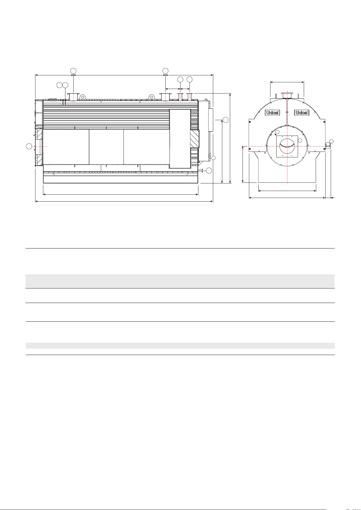
2.3 - DIMENSIONS
BP
TERNOX 2500 2S STD - 2200 2S Low NOx - 1800 2S Low NOx E
TERNOX 3500 2S STD - 3050 2S Low NOx - 2350 2S Low NOx E
E
T8
1 Panel board
2 Burner connection flange
3 Smoke chamber cleaning door
4 Flame control warning light
T6
T7
T1
T2
F
T3
T3
G
M
HQ
T5
4
2
1
C
I
3
T4
D
N
L
A
T1 Heating flow
T2 Heating return
T3 Expansion vessel connection
T4 Boiler drain
T5 Chimney connection
T6 Probe holder conduit connection
T7 Probe holder conduit connection
T8 Burner connection
TERNOx 2S
Model
2500 2S STD
2200 2S Low NOx
1800 2S Low NOx E
3500 2S STD
3050 2S Low NOx
2350 2S Low NOx E
Useful
output
kW
1800 - 2500
1800 - 2200
1800
2350 - 3500
2350 - 3050
2350
Furnace
furnace
kW
1951 - 2753
1951 - 2406
1951
2537 - 3848
2537 - 3329
2537
Boiler
capacity
3790
4750
Water side
pressure
drop(**)
l
m.w.c.
0.26 - 0.50
0.26 - 0.39
0.26
0.43 - 0.95
0.43 - 0.72
0.43
(**) Pressure drops corresponding to a thermal variation of 15K.
TERNOx 2S
Model
2500 2S STD
2200 2S Low NOx
1800 2S Low NOx E
3500 2S STD
3050 2S Low NOx
2350 2S Low NOx E
A
mm
4225
4711
B
mm
1710
1830
C
mm
2010
2120
D
mm
3370
3824
E
mm
1940
1954
Flue gas
pressure
drop
mbar
3.77 - 7.50
3.77 - 5.73
3.77
3.48 - 8.00
3.48 - 5.99
3.48
DIMENSIONS
F
mm
820
1140
M
aximum
W
operating
pressure
boiler
G
mm
1465
1617
bar
eight
T1
T2
UNI 2278 PN16
kg
5500
6
6 7000 DN 65DN 200 Rp 1½ 620
mm
420
570
H
mm
1400
1480
I
CONNECTIONS
T3
UNI 2278 PN16
DN 50DN 200
L
mm
1350
1450
mm
800
800
M
T4
ISO 7/1
Rp 1½
mm
570
N
mm
1030
1080
T5
Øi
T7
T6
Ø
Ø
mm
mm
Rp 1/2
Rp 1/2
Rp 1/2 Rp 1/2
P
mm
245
245
mm
230
250
T8
Ø
mm
400
400
Q
10

TERNOX 4500 2S STD - 3800 2S Low NOx - 3000 2S Low NOx E
TERNOX 5800 2S STD - 5000 2S Low NOx - 4000 2S Low NOx E
TERNOX 7000 2S STD - 6300 2S Low NOx - 5100 2S Low NOx E
TERNOX 8500 2S STD - 7500 2S Low NOx - 5700 2S Low NOx E
TERNOX 10200 2S STD - 9500 2S Low NOx - 8400 2S Low NOx E
E
T8
T1 T2
F
T6 T7
D
A
1 Panel board
2 Burner connection flange
3 Smoke chamber cleaning door
4 Flame control warning light
TERNOx 2S
Model
4500 2S STD
3800 2S Low NOx
3000 2S Low NOx E
5800 2S STD
5000 2S Low NOx
4000 2S Low NOx E
7000 2S STD
6300 2S Low NOx
5100 2S Low NOx E
8500 2S STD
7500 2S Low NOx
5700 2S Low NOx E
10200 2S STD
9500 2S Low NOx
8400 2S Low NOx E
Useful
output
kW
3000 - 4500
3000 - 3800
3000
4000 - 5800
4000 - 5000
4000
5100 - 7000
5100 - 6300
5100
5700 - 8500
5700 - 7500
5700
8400 - 10200
8400 - 9500
8400
3239 - 4951
3239 - 4144
4325 - 6381
4325 - 5457
5529 - 7705
5529 - 6892
6169 - 9377
6169 - 8215
9128 - 11191
9128 - 10377
Furnace
furnace
kW
3239
4325
5529
6169
9128
T1 Heating flow
T2 Heating return
T3 Expansion vessel connection
T4 Boiler drain
Boiler
capacity
6400
8060
9760
11480
14960
Water side
pressure
drop(**)
l
m.w.c.
0.27 - 0.60
0.27 0.43
0.27
0.44 - 0.93
0.44 - 0.69
0.44
0.72 - 1.36
0.72 - 1.10
0.72
0.90 - 2.00
0.90 - 1.56
0.90
0.96 - 1.41
0.96 - 1.22
0.96
(**) Pressure drops corresponding to a thermal variation of 15K.
T3 T3
HQ
Flue gas
pressure
drop
mbar
3.64 - 8.50
3.64 - 5.96
3.64
4.36 - 9.50
4.36 - 6.95
4.36
4.89 - 9.50
4.89 - 7.60
4.89
4.76 - 11.0
4.76 - 8.44
4.76
8.32 - 12.50
8.32 - 10.75
8.32
G
T5
C
I
N
3
T4
T5 Chimney connection
T6 Probe holder conduit connection
T7 Probe holder conduit connection
T8 Burner connection
M
aximum
operating
pressure
boiler
bar
W
eight
T1
kg
6
6 10000 DN 80DN 250 Rp 1½ 660
6 11500 DN 100DN 250 Rp 1½ 720
6 13500 DN 100DN 250 Rp 1½ 820
6 17300 DN 100DN 300 Rp 1½ 820
8200
T2
UNI 2278 PN16
CONNECTIONS
T3
UNI 2278 PN16
DN 80DN 250 Rp 1½ 660
4
T4
ISO 7/1
mm
M
L
B
T5
Øi
2
T6
T7
Ø
Ø
mm
mm
Rp 1/2
Rp 1/2
Rp 1/2 Rp 1/2
Rp 1/2
Rp 1/2
Rp 1/2 Rp 1/2
Rp 1/2
Rp 1/2
P
T8
mm
500
500
500
500
500
1
Technical features
Ø
TERNOx 2S
Model
4500 2S STD
3800 2S Low NOx
3000 2S Low NOx E
5800 2S STD
5000 2S Low NOx
4000 2S Low NOx E
7000 2S STD
6300 2S Low NOx
5100 2S Low NOx E
8500 2S STD
7500 2S Low NOx
5700 2S Low NOx E
10200 2S STD
9500 2S Low NOx
8400 2S Low NOx E
A
mm
5134
5639
5875
6420
6772
B
mm
1980
2180
2320
2400
2650
C
mm
2360
2580
2700
2870
3080
D
mm
4174
4626
4840
5330
5632
E
mm
2017
2451
2505
2035
1406
DIMENSIONS
F
mm
1380
1400
1510
2590
3450
1737
1788
1860
1795
1916
mm
G
mm
550
600
550
480
550
H
mm
1620
1780
1870
1980
2080
I
L
mm
1550
1710
1850
1900
2080
M
mm
800
800
880
880
1000
N
mm
1180
1300
1350
1460
1560
mm
250
250
250
250
250
P
mm
300
300
350
350
350
Q
11
TERNOX 12500 2S STD
TERNOX 15000 2S STD
T1 T2
E
T6 T7
T8
1 Panel board
2 Burner connection flange
3 Smoke chamber cleaning door
4 Flame control warning light
F
T3 T3
G
M
HQ
T5
4
C
I
3
2
1
N
T4
D
A
T1 Heating flow
T2 Heating return
T3 Expansion vessel connection
T4 Boiler drain
T5 Chimney connection
T6 Probe holder conduit connection
T7 Probe holder conduit connection
T8 Burner connection
L
B
P
TERNOX
Model
12500 2S STD
15000 2S STD
Useful
output
kW
12500
15000
Furnace
furnace
kW
13789
16458
Boiler
capacity
24100
27300 1.46 - 2.20 9.72 - 15.0 6 30000 DN 125DN 350 DN 60 1000
Water side
pressure
drop(**)
l
m.w.c.
1.31 - 2.00
(**) Pressure drops corresponding to a thermal variation of 15K.
TERNOx
Model
12500 2S STD
15000 2S STD
A
mm
7211
7761
B
mm
3210
3320
C
mm
3715
3910
D
mm
6236
6736
E
mm
1643
1693
Flue gas
pressure
drop
mbar
8.93 - 14.0
DIMENSIONS
F
mm
3500
4000
M
aximum
operating
pressure
boiler
bar
G
mm
2068
2068
W
eight
T1
T2
UNI 2278 PN16
kg
25500
6
mm
650
650
H
mm
2700
2750
I
CONNECTIONS
T3
UNI 2278 PN16
DN 125DN 300 DN 60 820
L
mm
2400
2500
M
mm
1470
1470
ISO 7/1
T7
Ø
mm
Rp 1/2
mm
400
400
T8
Ø
mm
650
650
Q
mm
N
mm
1480
1583
T5
Øi
T6
Ø
mm
Rp 1/2
Rp 1/2 Rp 1/2
P
mm
230
230
T4
12

2.4 - OPERATING DATA ACCORDING TO UNI 10348
GAS-FIRED
TERNOX 2500
2S STD
Nominal heat output
Thermal output of furnace
Heat efficiency at nominal load (100%)
Heat efficiency at 30% load
Combustion efficiency at nominal load (100%)
Heat loss at casing (min.-max.)
Heat loss at chimney with burner on (min.-max.)
Heat loss at chimney with burner off (min.-max.)
Flue gas temperature tf-ta (min.-max.)
CO2 content
Flue gas mass flow rate (min.-max)
kW
kW
%
%
%
%
%
%
°C
%
kg/h
1800 - 2500
1951 - 2753
92.25 - 90.80
91.40
92.9 - 91.5
0.60 - 0.71
7.15 - 8.49
0.10
146.46 - 174
9.80
2932.8 - 4138.6
DIESEL OIL-FIRED TERNOX 2500
2S STD
Nominal heat output
Thermal output of furnace
Heat efficiency at nominal load (100%)
Heat efficiency at 30% load
Combustion efficiency at nominal load (100%)
Heat loss at casing (min.-max.)
Heat loss at chimney with burner on (min.-max.)
Heat loss at chimney with burner off (min.-max.)
Flue gas temperature tf-ta (min.-max.)
CO
content
2
Flue gas mass flow rate (min.-max)
kW
kW
%
%
%
%
%
%
°C
%
kg/h
1800 - 2500
1951 - 2753
92.25 - 90.80
91.40
92.9 - 91.5
0.60 - 0.71
7.15 - 8.49
0.10
156.73 - 186.20
12.80
2987.9 - 4216.3
TERNOX 2200
2S LOW NOx
1800 - 2200
1951 - 2406
92.25 - 91.45
91.40
92.9 - 92.1
0.60 - 0.65
7.15 - 7.90
0.10
146.46 - 161.92
9.80
2932.8 - 3616.1
TERNOX 2200
2S LOW NOx
1800 - 2200
1951 - 2406
92.25 - 91.45
91.40
92.9 - 92.1
0.60 - 0.65
7.15 - 7.90
0.10
156.73 - 173.27
12.80
2987.9 - 3684.0
TERNOX 1800
2S LOW NOx E
1800
1951
92.25
91.40
92.9
0.60
7.15
0.10
146.46
9.80
2932.8
TERNOX 1800
2S LOW NOx E
1800
1951
92.25
91.40
92.9
0.60
7.15
0.10
156.73
12.80
2987.9
Technical features
GAS-FIRED
Nominal heat output
Thermal output of furnace
Heat efficiency at nominal load (100%)
Heat efficiency at 30% load
Combustion efficiency at nominal load (100%)
Heat loss at casing (min.-max.)
Heat loss at chimney with burner on (min.-max.)
Heat loss at chimney with burner off (min.-max.)
Flue gas temperature tf-ta (min.-max.)
content
CO
2
Flue gas mass flow rate (min.-max)
DIESEL OIL-FIRED
Nominal heat output
Thermal output of furnace
Heat efficiency at nominal load (100%)
Heat efficiency at 30% load
Combustion efficiency at nominal load (100%)
Heat loss at casing (min.-max.)
Heat loss at chimney with burner on (min.-max.)
Heat loss at chimney with burner off (min.-max.)
Flue gas temperature tf-ta (min.-max.)
CO
content
2
Flue gas mass flow rate (min.-max)
kW
kW
%
%
%
%
%
%
°C
%
kg/h
kW
kW
%
%
%
%
%
%
°C
%
kg/h
TERNOX 3500
2S STD
2350 - 3500
2537 - 3848
92.64 - 90.95
91.40
93.2 - 91.7
0.58 - 071
6.78 - 8.34
0.10
139.00 - 171.00
9.80
3813.1 - 5784.7
TERNOX 3500
2S STD
2350 - 3500
2537 - 3848
92.64 - 90.95
91.40
93.2 - 91.7
0.58 - 071
6.78 - 8.34
0.10
148.67 - 182.90
12.80
3884.6 - 5893.1
TERNOX 3050
2S LOW NOx
2350 - 3050
2537 - 3329
92.64 - 91.62
91.40
93.2 - 92.3
0.58 - 0.65
6.78 - 7.73
0.10
139.0 - 158.35
9.80
3913.1 - 5003.7
TERNOX 3050
2S LOW NOx
2350 - 3050
2537 - 3329
92.64 - 91.62
91.40
93.2 - 92.3
0.58 - 0.65
6.78 - 7.73
0.10
148.67 - 169.37
12.80
3884.6 - 5097.5
TERNOX 2350
2S LOW NOx E
2350
2537
92.64
91.40
93.2
0.58
6.78
0.10
139
9.80
3813.1
TERNOX 2350
2S LOW NOx E
2350
2537
92.64
91.40
93.2
0.58
6.78
0.10
148.67
12.80
3884.6
13

GAS-FIRED
Nominal heat output
Thermal output of furnace
Heat efficiency at nominal load (100%)
Heat efficiency at 30% load
Combustion efficiency at nominal load (100%)
Heat loss at casing (min.-max.)
Heat loss at chimney with burner on (min.-max.)
Heat loss at chimney with burner off (min.-max.)
Flue gas temperature tf-ta (min.-max.)
content
CO
2
Flue gas mass flow rate (min.-max)
kW
kW
%
%
%
%
%
%
°C
%
kg/h
TERNOX 4500
2S STD
3000 - 4500
3239 - 4951
92.62 - 90.90
91.40
93.2 - 91.6
0.58 - 0.71
6.80 - 8.39
0.10
139.31 - 172.00
9.80
4868.5 - 7441.4
TERNOX 3800
2S LOW NOx
3000 - 3800
3239 - 4144
92.62 - 91.70
91.40
93.2 - 92.4
0.58 - 0.65
6.80 - 7.65
0.10
139.31 - 156.79
9.80
4868.5 - 6228.9
TERNOX 3000
2S LOW NOx E
3000
3239
92.62
91.40
93.2
0.58
6.80
0.10
139.31
9.80
4868.5
DIESEL OIL-FIRED
Nominal heat output
Thermal output of furnace
Heat efficiency at nominal load (100%)
Heat efficiency at 30% load
Combustion efficiency at nominal load (100%)
Heat loss at casing (min.-max.)
Heat loss at chimney with burner on (min.-max.)
Heat loss at chimney with burner off (min.-max.)
Flue gas temperature tf-ta (min.-max.)
CO
content
2
Flue gas mass flow rate (min.-max)
GAS-FIRED
Nominal heat output
Thermal output of furnace
Heat efficiency at nominal load (100%)
Heat efficiency at 30% load
Combustion efficiency at nominal load (100%)
Heat loss at casing (min.-max.)
Heat loss at chimney with burner on (min.-max.)
Heat loss at chimney with burner off (min.-max.)
Flue gas temperature tf-ta (min.-max.)
CO
content
2
Flue gas mass flow rate (min.-max)
kW
kW
%
%
%
%
%
%
°C
%
kg/h
kW
kW
%
%
%
%
%
%
°C
%
kg/h
TERNOX 4500
2S STD
3000 - 4500
3239 - 4951
92.62 - 90.90
91.40
93.2 - 91.6
0.58 - 0.71
6.80 - 8.39
0.10
149.03 - 184.00
12.80
4959.9 - 7581.0
TERNOX 5800
2S STD
4000 - 5800
4324 - 6381
92.50 - 90.90
91.40
93.1 - 91.6
0.59 - 0.71
6.91 - 8.39
0.10
141.70 - 172.00
9.80
6500.2 - 9591.1
TERNOX 3800
2S LOW NOx
3000 - 3800
3239 - 4144
92.62 - 91.70
91.40
93.2 - 92.3 0.58 -
0.65
6.80 - 7.65
0.10
149.03 - 167.73
12.80
4959.9 - 6345.8
TERNOX 5000
2S LOW NOx
4000 - 5000
4324 - 5457
92.50 - 91.62
91.40
93.1 - 92.3
0.59 - 0.65
6.91 - 7.73
0.10
141.70 - 158.42
9.80
6500.2 - 8203.0
TERNOX 3000
2S LOW NOx E
3000
3239
92.62
91.40
93.2
0.58
6.80
0.10
149.03
12.80
4959.9
TERNOX 4000
2S LOW NOx E
4000
4324
92.50
91.40
93.1
0.59
6.91
0.10
141.70
9.80
6500.2
DIESEL OIL-FIRED
Nominal heat output
Thermal output of furnace
Heat efficiency at nominal load (100%)
Heat efficiency at 30% load
Combustion efficiency at nominal load (100%)
Heat loss at casing (min.-max.)
Heat loss at chimney with burner on (min.-max.)
Heat loss at chimney with burner off (min.-max.)
Flue gas temperature tf-ta (min.-max.)
CO
content
2
Flue gas mass flow rate (min.-max)
14
kW
kW
%
%
%
%
%
%
°C
%
kg/h
TERNOX 5800
2S STD
4000 - 5800
4324 - 6381
92.50 - 90.90
91.40
93.1 - 91.6
0.59 - 0.71
6.91 - 8.39
0.10
151.58 - 184.00
12.80
6622.2 - 9771.1
TERNOX 5000
2S LOW NOx
4000 - 5000
4325 - 5457
92.50 - 91.62
91.40
93.1 - 92.3
0.59 - 0.65
6.91 - 7.73
0.10
151.58 - 169.47
12.80
6622.2 - 8356.9
TERNOX 4000
2S LOW NOx E
4000
4324
92.50
91.40
93.1
0.59
6.91
0.10
151.58
12.80
6622.2

GAS-FIRED
Nominal heat output
Thermal output of furnace
Heat efficiency at nominal load (100%)
Heat efficiency at 30% load
Combustion efficiency at nominal load (100%)
Heat loss at casing (min.-max.)
Heat loss at chimney with burner on (min.-max.)
Heat loss at chimney with burner off (min.-max.)
Flue gas temperature tf-ta (min.-max.)
content
CO
2
Flue gas mass flow rate (min.-max)
kW
kW
%
%
%
%
%
%
°C
%
kg/h
TERNOX 7000
2S STD
5100 - 7000
5529 - 7705
92.25 - 90.85
91.40
92.9 - 91.6
0.61 - 0.71
7.15 - 8.44
0.10
146.49 - 173.00
9.80
8310.3 - 11581.7
TERNOX 6300
2S LOW NOx
5100 - 6300
5529 - 6892
92.25 - 91.41
91.40
92.9 - 92.1
0.61 - 0.65
7.15 - 7.94
0.10
146.49 - 162.81
9.80
8310.3 - 10360.0
TERNOX 5100
2S LOW NOx E
5100
5529
92.25
91.40
92.9
0.61
7.15
0.10
146.48
9.80
8310.3
DIESEL OIL-FIRED
Nominal heat output
Thermal output of furnace
Heat efficiency at nominal load (100%)
Heat efficiency at 30% load
Combustion efficiency at nominal load (100%)
Heat loss at casing (min.-max.)
Heat loss at chimney with burner on (min.-max.)
Heat loss at chimney with burner off (min.-max.)
Flue gas temperature tf-ta (min.-max.)
CO
content
2
Flue gas mass flow rate (min.-max)
GAS-FIRED
Nominal heat output
Thermal output of furnace
Heat efficiency at nominal load (100%)
Heat efficiency at 30% load
Combustion efficiency at nominal load (100%)
Heat loss at casing (min.-max.)
Heat loss at chimney with burner on (min.-max.)
Heat loss at chimney with burner off (min.-max.)
Flue gas temperature tf-ta (min.-max.)
CO
content
2
Flue gas mass flow rate (min.-max)
kW
kW
%
%
%
%
%
%
°C
%
kg/h
kW
kW
%
%
%
%
%
%
°C
%
kg/h
TERNOX 7000
2S STD
5100 - 7000
5529 - 7705
92.25 - 90.85
91.40
92.9 - 91.6
0.61 - 0.71
7.15 - 8.44
0.10
156.65 - 185.00
12.80
8465.9 - 11798.7
TERNOX 8500
2S STD
5700 - 8500
6169 - 9376
92.40 - 90.65
91.40
93.0 - 91.4
0.58 - 0.71
7.01 - 8.64
0.10
143.78 - 177.00
9.80
9272.2 - 14093.8
TERNOX 6300
2S LOW NOx
5100 - 6300
5529 - 6892
92.25 - 91.41
91.40
92.9 - 92.1
0.61 - 0.65
7.15 - 7.94
0.10
156.65 - 174.10
12.80
8465.9 - 10554.1
TERNOX 7500
2S LOW NOx
5700 - 7500
6169 - 8214
92,40 - 91,30
91.40
93.0 - 92.0
0.58 - 0.65
7.01 - 8.04
0.10
143.78 - 164.93
9.80
9272.2 - 12347.4
TERNOX 5100
2S LOW NOx E
5100
5529
92.25
91.40
92.9
0.61
7.15
0.10
156.65
12.80
8465.9
Technical features
TERNOX 5700
2S LOW NOx E
5700
6169
92.40
91.40
93.0
0.58
7.01
0.10
143.78
9.80
9272.2
DIESEL OIL-FIRED
Nominal heat output
Thermal output of furnace
Heat efficiency at nominal load (100%)
Heat efficiency at 30% load
Combustion efficiency at nominal load (100%)
Heat loss at casing (min.-max.)
Heat loss at chimney with burner on (min.-max.)
Heat loss at chimney with burner off (min.-max.)
Flue gas temperature tf-ta (min.-max.)
CO
content
2
Flue gas mass flow rate (min.-max)
kW
kW
%
%
%
%
%
%
°C
%
kg/h
TERNOX 8500
2S STD
5700 - 8500
6169 - 9377
92.40 - 90.65
91.40
93.0 - 91.4
0.58 - 0.71
7.02 - 8.64
0.10
153.94 - 189.50
12.80
9446.8 - 14359.4
TERNOX 7500
2S LOW NOx
5700 - 7500
6169 - 8215
92.40 - 91.29
91.40
93.0 - 91.9
0.58 - 0.65
7.02 - 8.06
0.10
153.94 - 176.58
12.80
9446.8 - 12579.9
TERNOX 5700
2S LOW NOx E
5700
6169
92.40
91.40
93.0
0.58
7.02
0.10
153.94
12.80
9446.8
15

GAS-FIRED
Nominal heat output
Thermal output of furnace
Heat efficiency at nominal load (100%)
Heat efficiency at 30% load
Combustion efficiency at nominal load (100%)
Heat loss at casing (min.-max.)
Heat loss at chimney with burner on (min.-max.)
Heat loss at chimney with burner off (min.-max.)
Flue gas temperature tf-ta (min.-max.)
CO
content
2
Flue gas mass flow rate (min.-max)
kW
kW
%
%
%
%
%
%
°C
%
kg/h
TERNOX 10200
2S STD
8400 - 10200
9128 - 11191
92.02 - 91.14
91.40
92.7 - 91.9
0.64 - 0.71
7.33 - 8.15
0.10
150.34 - 167.00
9.80
13721.2 - 16822.0
TERNOX 9500
2S LOW NOx
8400 - 9500
9128 - 10377
92.02 - 91.55
91.40
92.7 - 92.2
0.64 - 0.65
7.33 - 7.80
0.10
150.34 - 159.88
9.80
13721.2 - 15579.9
TERNOX 8400
2S LOW NOx E
8400
9128
92.03
91.40
92.7
0.64
7.33
0.10
150.34
9.80
13720.5
DIESEL OIL-FIRED
Nominal heat output
Thermal output of furnace
Heat efficiency at nominal load (100%)
Heat efficiency at 30% load
Combustion efficiency at nominal load (100%)
Heat loss at casing (min.-max.)
Heat loss at chimney with burner on (min.-max.)
Heat loss at chimney with burner off (min.-max.)
Flue gas temperature tf-ta (min.-max.)
CO
content
2
Flue gas mass flow rate (min.-max)
GAS-FIRED
Nominal heat output
Thermal output of furnace
Heat efficiency at nominal load (100%)
Heat efficiency at 30% load
Combustion efficiency at nominal load (100%)
Heat loss at casing (min.-max.)
Heat loss at chimney with burner on (min.-max.)
Heat loss at chimney with burner off (min.-max.)
Flue gas temperature tf-ta (min.-max.)
CO
content
2
Flue gas mass flow rate (min.-max)
kW
kW
%
%
%
%
%
%
°C
%
kg/h
kW
kW
%
%
%
%
%
%
°C
%
kg/h
TERNOX 10200
2S STD
8400 - 10200
9128 - 11191
92.02 - 91.14
91.40
92.7 - 91.9
0.64 - 0.71
7.33 - 8.15
0.10
160.78 - 178.60
12.80
13978.3 - 17137.3
TERNOX 12500
2S STD
10100 - 12500
11012 - 13789
91.72 - 90.65
91.40
92.3 - 91.4
0.58 - 0.71
7.70 - 8.64
0.10
157.83 - 177.00
9.80
16552,5 - 20726,2
TERNOX 9500
2S LOW NOx
8400 - 9500
9128 - 10377
92.02 - 91.55
91.40
92.7 - 92.2
0.64 - 0.65
7.33 - 7.80
0.10
160.78 - 170.98
12.80
13978.3 - 15890.1
TERNOX 15000
2S STD
12200 - 15000
13251 - 16458
92.07 - 91.14
91.40
92.7 - 91.9
0.64 - 0.71
7.29 - 8.15
0.10
149.40 - 167.00
9.80
19918.5 - 24738.3
TERNOX 8400
2S LOW NOx E
8400
9128
92.03
91.40
92.7
0.64
7.33
0.10
160.78
12.80
13977.6
DIESEL OIL-FIRED
Nominal heat output
Thermal output of furnace
Heat efficiency at nominal load (100%)
Heat efficiency at 30% load
Combustion efficiency at nominal load (100%)
Heat loss at casing (min.-max.)
Heat loss at chimney with burner on (min.-max.)
Heat loss at chimney with burner off (min.-max.)
Flue gas temperature tf-ta (min.-max.)
CO
content
2
Flue gas mass flow rate (min.-max)
16
kW
kW
%
%
%
%
%
%
°C
%
kg/h
TERNOX 12500
2S STD
10100 - 12500
11012 - 13789
91.71 - 90.65
91.40
92.3 - 91.4
0.58 - 0.71
7.70 - 8.64
0.10
168.89 - 189.40
12.80
16863.5 - 21115.7
TERNOX 15000
2S STD
12200 - 15000
13251 - 16458
92.07 - 91.14
91.40
92.7 - 91.9
0.64 - 0.71
7.29 - 8.15
0.10
159.78 - 178.60
12.80
20291.8 - 25201.8

3
INSTRUCTIONS FOR
INSTALLATION
3.1 - GENERAL WARNINGS
ATTENTION!
This boiler is intended solely for the use for
which it was expressly designed. Any other
use is to be considered improper and therefore dangerous.
This boiler heats water at a temperature
lower than the atmospheric pressure boiling
temperature.
Before connecting the boiler, have professionally
qualified personnel:
a) Thoroughly wash all the piping of the system
to remove any residues or impurities which
could jeopardise proper operation of the
boiler, even from a hygienic point of view.
b) Check that boiler is set up to operate with the
available type of fuel.
The type of fuel can be seen written on the
package and on the technical feature plate.
c) Check that the chimney/flue has an appropri-
ate draught, without any bottlenecks, and that
no exhausts from other appliances are inserted, unless the flue has been implemented to
accommodate several utilities according to
specific standards and prescriptions in force.
Only after this check can the fitting between
the boiler and chimney/flue be mounted.
ATTENTION!
In rooms with the presence of aggressive
vapours or dust, the appliance must operate
independently from the air inside the installation room!
ATTENTION!
The appliance must be installed by a qualified
technician with the technical-professional
requirements according to law 46/90 which,
under his own responsibility, guarantees
compliance with standards according to
good practice rules.
ATTENTION!
Mount the appliance respecting the minimum
distances required for installation and maintenance.
The boiler must be connected to a heating
system compatible with its performance and
output.
3.2 - INSTALLATION STANDARDS
It must be installed by a professionally qualified technician, who
shall take the responsibility of observing all local and/or
national laws published in the official journal, as well as
applicable technical standards.
3.3 - INSTALLATION ON
OLD OR RETROFITTABLE SYSTEMS
Before installing this appliance on old systems, check that:
- The flue is able to withstand the temperature generated by
the combustion products, has been measured and designed
according to the regulations in force, is airtight and insulated,
and does not feature obstructions or constrictions.
- The flue has a device for releasing condensation.
- The electrical system has been set up by a qualified technician in compliance with the rules in force.
- The rate, head and direction of the flow of the circulation
pumps are appropriate.
- The expansion vessel(s) can fully absorb dilation of the fluid in the system.
- The fuel adduction line and the tank, if any, are made ac-
cording to relevant standards in force.
- The expansion vessels can fully absorb dilation of the fluid
in the system.
- The system has been cleaned and cleared of all sludge
and scale, has been vented, and all its seals have been
checked.
- There is a treatment system for feed/recirculation water
(see reference values).
Technical features and dimensions
17

3.4 - PACKAGING
TERNOX 2S boilers are supplied with casing and with the door
and smoke chamber assembled.
The panel and accessories are inside the combustion chamber.
Upon reception, make sure that the supply is complete and
undamaged.
The document envelope, besides the appliance, contains:
- Hydraulic test certificate
- Heating system booklet
- System manager operating instructions
- Installation and maintenance instruction booklet
- Warranty
- Local ventilation requirements label.
3.5 - HANDLING
TERNOX 2S boilers are equipped with lifting eyebolts.
Pay attention when handling the boiler and use equipment suitable for its weight.
18

3.6 - POSITIONING IN BOILER ROOM
TERNOX 2S boilers must be installed in rooms for exclusive
use complying with Technical Standards and Legislation in
force and with sufficiently sized air vents.
The ventilation openings must be permanent, communicating
directly with the outside and must be positioned high or low
according to standards in force.
The location of the ventilation openings, the fuel supply trains,
electric energy supply and lighting must comply with current
legal provisions in relation to the type of fuel used.
To make it easier to clean the smoke circuit, a free space must
be left in front of the boiler no less than the length of the boiler
body and, in any case, never less than 1300 mm. It must be
checked that with the door/s open 90°, the distance between
the door and the adjacent wall X is at least equal to the length
of the burner.
The boiler must rest on a perfectly level surface.
It is advisable to provide a flat, level cement basement capable
of bearing the weight of the boiler full of water. For the dimensions of the basement, see the dimensions R x B (dimensions
table).
If the burner is fed with fuel gas weighing more than air, the
electrical parts must be placed higher than 500 mm above the
ground.
The appliance cannot be installed outdoors as it was not so
designed and does not have automatic antifreeze systems.
Technical features and dimensions
19

3.7 - HYDRAULIC CONNECTIONS
ATTENTION!
Before connecting the boiler to the heating
system, thoroughly clean the piping with an
appropriate product compliant with UNI-CTI
8065, in order to eliminate metallic residue
from processing and welding, oil and grease
which could be present and which, reaching
the boiler, could alter its functioning.
Attention!
The fittings of the boiler must not take the
weight of the connecting pipes of the system; suitable supporting devices should be
installed to do this.
The dimensions of the supply and return pipes for each boiler
model are given in the DIMENSIONS table.
The connection pipes of the expansion vessel will start from the
T3 attachment (see DIMENSIONS TABLES) and must have no
shut-off valve.
Safety valve drain
Install a safety pressure valve on the flow pipe within 0.5 m of
the starting flange, sized according to the capacity of the boiler
and in compliance with local standards in force.
It is prohibited to place any type of shut-off valve between the
boiler and expansion vessel or between the boiler and safety
pressure valves. The valves used must be adjusted to trigger
not beyond the maximum allowed operating pressure.
3.9.1 - RECIRCULATION PUMP
Check that the system is fitted with a sufficient number of air
release valves.
Connection of expansion vessel
TERNOX 2S boilers are suitable for operating with forced water
circulation both with the expansion vessel opened or closed.
An expansion vessel is always necessary to compensate the
increase in water volume due to heating.
In the first case, the hydrostatic column must be
at least 3 m above the casing of the boiler and
sufficient to contain the volume increase of all
the water of the system between the exposed
surface of the water in the tank and the overflow
pipe.
3.8 - FILLING AND EMPTYING
THE SYSTEM
Attention!
Do not mix the heating water with incorrect
concentrations of antifreeze or anti-corrosion
substances! This could damage the gaskets
and cause noise during operation.
Unical will not be held liable for damage to
persons, animals or objects due to failure to
comply with the above instruction.
TERNOX 2S boilers must always operate with forced water
circulation and a minimum return temperature of 55°C.
It is therefore recommended to use a recirculation pump, which
also has an anti-condensation function, installed between the
flow and return connections upstream the mixing valve.
This pump is dimensioned according to the formula:
Q = P x 22
where Q = Flow rate in l/hr
P = Nominal output of boiler in kW
and head 1÷2 m H2O
The values displayed in the table can be used
as a reference.
TOTAL HARDNESS ppm 10
ALKALINITY mg/l CaCO3 750
PH 8÷9
SILICA ppm 100
CHLORIDES ppm 3500
When all system connections have been completed, the circuit
can be filled.
A specific tap can be connected to the T4 attachment at the rear of the boiler for filling and draining.
20
ATTENTION!
ANY DAMAGE TO THE BOILER CAUSED BY
THE FORMATION OF FOULING OR BY CORROSIVE WATER WILL NOT BE COVERED BY
THE WARRANTY.

3.9 - GAS CONNECTION
Connecting Gas
Danger!
The gas connection must be carried out only
by a qualified installer who must respect and
apply that foreseen by relevant laws in force
in the local prescriptions of the supply company. Incorrect installation can cause damage
to persons, animals and objects for which the
manufacturer cannot be held responsible.
Before installation, we recommend a thorough inner cleaning of all fuel adduction
piping to remove any residue which could
jeopardise proper operation of the boiler.
If you smell gas:
a) Do not turn electric switches on or off, use
a telephone or any other object which can
create sparks;
b) Immediately open doors and windows to
create an air current to air out the room;
c) Shut the gas cocks;
d) Request the intervention of professionally
qualified personnel.
3.10 - CONNECTION TO THE FLUE
The TERNOX 2S boiler can be attached to the chimney in different ways; straight pipes or elbows can be used to exit from
the rear, on the left, on the right, or else vertically to enter the
flue at a higher level.
It is recommended to insulate the pipe connecting to the chimney
to reduce heat loss and noise.
Along the section connecting the boiler to the flue there
must be suitable points for measuring flue gas temperature and analysing combustion products.
The flue gas duct and the fitting to the flue must be implemented in compliance with Standards and Legislation in force, with
rigid ducts resistant to heat, condensation, mechanical stress
and airtight.
The flue must guarantee the minimum negative pressure foreseen by Standards in force, considering “zero” pressure at the
flue duct fitting.
Inadequate or improperly sized flues and flue ducts can amplify
combustion noise, generate condensation problems and negatively affect combustion parameters.
Non-insulated exhaust pipes are a potential source of risk.
The seals of the junctions must be made with materials resistant to temperatures of at least 250°C.
Along the section connecting the boiler to the flue there must
be suitable points for measuring flue gas temperature and analysing combustion products.
Refer to national and local regulations in force for that which
regards the cross-section and height of the chimney.
Technical features and dimensions
21

3.11 - FURNACE DOOR: ADJUSTMENT,
OPENING AND CLOSING
IMPORTANT
- The door of the boiler must be opened when it is cooled off
to avoid thermal shocks.
- The rear factory material of the door can show cracks after
a short time of operation; this however does not reduce its
insulation capacity nor jeopardise its lifespan.
The door is hinged and fixed according to the indicated diagram:
In these cases, the two hinges on the left are normally used as
rotation hinges (from right to left), while the two on the right are
used as closing hinges.
It will be exactly the opposite when the door is opened from
left to right.
To invert rotation, just move the door support lock nut.
The following adjustments can be made on the door:
A) Adjustment in the vertical direction: by acting on the nut
of the upper hinge pin on which the door turns.
B) Adjustment in the transverse direction: loosen the hinges
fixed on the front plate of the boiler and move them sideways.
C) Adjustment in the axial direction: by adjusting the tightening
nuts.
3.12 - BURNERS
The burners operating with the TERNOX 2S boilers must have
the EC certification and comply with:
- Gas appliance directive (90/396/EEC);
- EMC Directive - Electromagnetic Compatibility (89/336/EEC).
They must also be approved according to the specifications:
- UNI EN 267 - test methods for atomizing oil burners of the
monobloc type.
- UNI EN 676 - air-blown burners for gaseous fuel.
- Efficiency Directive (92/42 EEC).
22

3.12.1 - SELECTING THE BURNER
L
Ø A
The correct choice and adjustment of the burner are fundamental
for optimal operation of the boiler and therefore must be done
carefully and not underestimated.
The burner must be chosen verifying that its firing rate (fuel
capacity - combustion chamber pressure) is compatible with the
same features declared for the boiler.
Remember that pressure drops on the flue side of the boiler,
namely combustion chamber counter pressure, refer to zero
pressure at the base of the chimney.
It is also recommended that the burner blast tube be no shorter
than the minimum dimension shown in the following table and
that the flame which must be implemented be suitable for the
characteristics of the combustion chamber.
The manufacturing companies of the burners can supply the
dimensions of the flames which their appliances develop, especially those approved based on the standards indicated above.
DIMENSIONS OF BURNER BLAST TUBE
TERNOx
2500
3500
4500
5800
7000
8500
10200
12500
15000
øA
mmL mm (min)
400
400
500
500
500
500
500
650
650
370
370
410
410
410
450
450
450
450
mm (max)
L
520
520
560
560
560
650
650
650
650
3.12.2 - INSTALLATION OF THE BURNER
The burner must be mounted to the door of the boiler guaranteeing perfect sealing of the combustion products.
The burner is supplied with a piece of ceramic fibre cord which
must be placed on the blast tube of the burner to fully seal
the space between the blast tube and the slot in the door.
Make sure that no gaps remain between the blast tube and the
slot on the refractory material inside the door.
3.12.3 - CONNECTING FLAME CONTROL
WARNING LIGHT TO BURNER
The flame control warning light is supplied with a threaded 1/8”
connection with a 9mm pressure test nipple mounted on it, to
be used with a silicone tube to measure back pressure in the
combustion chamber.
In place of this test nipple, which must be kept, an appropriate
fitting will be mounted to connect the flame control warning light
directly to the pressure chamber downstream the burner fan by
means of a copper tube.
The air blown by the fan will conveniently cool the warning light
glass and keep it from blackening.
If the cooling tube is not connected to the warning light, it could
break.
Should a cone larger than the diameter of the blast tube be
mounted, it must be removed before mounting the burner on
the support plate and put back afterwards.
With the burner mounted, check that the flexible hoses of the
liquid fuel and the electric cables are long enough to allow the
door to open 90°.
For gas-fired burners, flexible hoses cannot be used for connections. Therefore it must be equipped with a threaded or flanged
joint for disconnecting the final section of the gas adduction tube.
Technical features and dimensions
ATTENTION: the flame control warning light
can be very hot; therefore pay the utmost
attention.
23

3.13 - MOUNTING ELECTRIC PANEL
TERNOX 2S boilers are supplied with casing. Therefore to mount
the panel board, proceed as follows:
A) Dismount the right upper walkways (pos. 1 and 2).
B) Fix the support box of the panel board to the bracket on the
right side of the boiler.
C) Remove the lower cover pos. 4 from the support box of the
panel board.
Fasten the panel board (pos. 5) to the support box pos. 3.
D) Rotate the cover of the panel board frontwards after having
removed the two screws on the side and insert the electric
inlet cables and the outlet probe capillaries through the slots
at the base.
Insert the thermostat probe capillaries in the tube designed
for their passage, that is placed under the casing (see detail
“A”).
Pay special attention when unrolling the capillaries and insert
the bulbs in the two holders, inserting the contact springs and
blocking the capillaries with the fixing springs.
E) After having carried out the electric connections, close the
panel board and reposition the lower cover of the support box.
F) Remount the upper walkways.
24

3.14 - ELECTRICAL CONNECTIONS
General warnings
The electrical safety of the appliance is guaranteed only when it has been properly connected
to an efficient earthing system carried out as
intended by safety standards in force: pipes of the
gas, water and heating systems are absolutely
unsuitable as earthing electrodes.
It is necessary to verify this fundamental safety requirement. If
in doubt, have the electric system carefully checked by professionally qualified personnel as the manufacturer is not liable for
damage caused by failure to provide an earthing system.
Have professionally qualified personnel check
that the electric system is adequate for the maximum power absorbed by the appliance, indicated
on the data plate. Make sure in particular that
the cross-section of the cables is suitable for the
power absorbed by the appliance.
Use of any type of component using electric energy requires the
observance of some fundamental rules, such as:
• do not touch the appliance with wet and/or moist parts of the
body and/or in bare feet;
• do not pull the electric cables;
• do not leave the appliance exposed to atmospheric agents
(rain, sun, etc.) unless expressly designed;
• do not allow children or unskilled persons to use the appli-
ance.
230V electric power supply connection
The electrical connections are illustrated in chap. 3.15 .... 3.19.
The boiler installation requires a connection to a 230 V - 50 Hz
electric mains: this connection must be properly carried out as
provided for by current IEC regulations.
Danger!
Only a qualified technician may perform the
electrical installation.
Before performing connections or any type
of operation on electrical parts, always disconnect electrical power and make sure that
it cannot be reconnected accidentally.
Remember that a bipolar switch must be installed on the boiler
power line with over 3 mm between contacts, easy to access,
making maintenance quick and safe.
Technical features and dimensions
25

3.15 - STANDARD PANEL BOARD
The main switch 11 powers the board and the equipment connected to it.
Switches 12 and 13 in turn cut power to the burner and to the
C.H. pump.
Thermostat 32 adjusts the working temperature of the boiler.
The working thermostat is provided with two switching contacts
to control the two-stage burners.
The differential between the two contacts is 6°C (not adjustable).
11 Main switch with indicator light
12 Burner switch
13 System pump switch
31 Safety thermostat
The minimum thermostat, which can only be accessed after
having lifted the cover of the electric control board, stops the
C.H. pump until the boiler reaches the temperature of 50°C.
The electric power line of the boiler's control board must have a
switch with protective fuses.
32 Working thermostat
41 General fuse
42 Boiler thermometer
For use of the panel board, see the system manager instruction manual
If the Room thermostat is mounted,
remove bridge 11-12
7-pole plug
Plug stage 2
(optional)
Ph Phase (230V ~50Hz)
N Neutral
F1 General fuse (max 4A)
Ib Burner switch
IG Main switch with indicator light
Ipi System pump switch
Ta Room thermostat
26
Te1 Working thermostat stage 1
(60°C÷90°C)
Te2 Working thermostat stage 2
(54°C÷84°C)
Tm Minimum thermostat (50°C)
Ts Safety thermostat (100°C)
Pi System pump
A Possible repetition of burner block
B Possible working hour counter stage 1
C Possible working hour counter stage 2

3.16 - HYDRAULIC AND ELECTRICAL
SYSTEM CONNECTION
The following figures show the typical layout of the connection
of the boiler to the heating system with production of domestic
hot water.
Remember that TERNOX boilers operate with forced circulation.
TERNOx BOILER
Key:
Pr = recirculation pump
VM = zone mixing valve
Pi = heating system pump
VE = expansion vessel
IR = heating system distribution
Ps = domestic water recirculation pump
Pc = domestic hot water production charge pump
TA = room thermostat
The standard panel board of the TERNOX boiler automatically
switches the burner off when the temperature in the boiler reaches the value set on the control thermostat.
It also manages the C.H. pump, which will only be activated
when the minimum boiler temperature of 50°C has been reached
(anti-condensation protection temperature).
The pump will switch off when the lower threshold of 50°C (decreasing) is reached.
DOMESTIC HOT WATER
PRODUCER
The panel is set up to manage dual-stage or modulating burners.
With this layout configuration, the DHW storage tank loading
pump will have the priority over the heating C.H. pump.
Technical features and dimensions
27

POWER SUPPLY
TO THE 7-POLE SOCKET
OF THE BURNER
POWER SUPPLY
POWER SUPPLY
TERNOx BOILER
DOMESTIC HOT WATER
PRODUCER
NOTE: With absorption beyond 4A, place adequate contactors between the panel board and the loads
28

3.17 - OPTIONAL MASTER PANEL BOARD
The main switch 14 powers the board and the equipment connected to it.
The switches 18 and 19 control the burner and P1 pump if the
boiler operates in cascade.
The switches 20 and 21 control the Z1 pump (direct) and Z2
pump (mixed).
The thermostat adjusts the working temperature of the boiler:
to achieve this, the thermostat must be placed at maximum
full-scale pos. 33 .
Modulation of the burner will be managed by heat control.
The electric power line of the boiler's control board must have a
switch with protective fuses.
User
System
Service
Visual Inf.
Date/Time/Holiday
Solar/MF
Hot Water
Technician
Time Progr.
Heating circuit I
Heating circuit II
14 Main switch with indicator light
16 General fuse
18 Burner switch
19 P1 C.H. pump switch (cascade)
20 Pz1 direct zone C.H. pump switch
21 Pz2 mixed zone C.H. pump switch
33 Working thermostat
35 Safety thermostat
For use of the panel board, see the system manager instruction manual
The heating controller probes (boiler, storage tank, external,
flow) are included in the supply; the ambient probes 1 and 2
are optional; the mixing valve and relative control motor are not
included in the supply.
The optional panel board of the TERNOX 2S boiler automatically switches the burner off when the temperature in the boiler
reaches the value set on the heating controller.
It also manages the pump to fill a storage tank for DHW production.
The heating systems are managed automatically based on the
data detected by the boiler, external, ambient and flow probes.
The high temperature zone C.H. pump is made ready for operation by the control switch pos. 20, and will only switch off when
the temperature set on the heating controller has been reached.
The low temperature zone C.H. pump is made ready for operation
by the control switch pos. 21, and will only switch off when the
temperature set on the heating controller has been reached.
The storage tank charge pump for DHW production switches on
automatically and will only switch off when the temperature set
on the heating controller has been reached.
Should ambient probes be mounted (optional), the room temperature will only be determined with the boiler curve set by
the program.
The panel is set up to manage the modulating burners.
With this system configuration, the heating controller is capable
of checking:
- direct zone system; the control unit commands the C.H. pump.
The room temperature is controlled by the programming
curves set in the heating controller;
- one zone system with motorised mixing valve: the flow probe
(downstream the mixing valve) must be fitted; the control unit
commands the C.H. pump and the mixing valve. The room
temperature is controlled by the programming curves set in
the heating controller;
- DHW production through storage tank;
- anti-legionella function with increase of water temperature
in storage tank (function not enabled in factory, but can be
enabled by customer).
Technical features and dimensions
29

E
L1 T2N S3T1 B4
IG
3
4
Ts
7695810
B
A
28 42
Ib
(0°÷100°C)
(110°C)
Te
14
18
33
35
N
230V~ 50Hz
(max 4A)
2
1
L1
2
C
Spina a 7 poli
16
F1 (max 6 A)
B5 T7 T8
11
13
12
Spina a 4 poli
T6
14 15 16 17 18 19 20 21 46 47 48 49 50 51 52 53 54 55
56
57
C
32 25
30 31 26
3727 38 39 40
41
teleruttore pompa
zona 1
teleruttore
pompa ricircolo
teleruttore pompa
zona 2
teleruttore pompa
boiler
teleruttore valvola
mix. zona 2
L1LLL
L
L2 NNNN
N
Pz1
Pr
Pz2 Pb
Zona mix 2
24 36
Ipz1
Ip1
Ipz2
20
19
21
29 43
c
E
1
2
44 45
34
35
HL-+
22 23
33
Nero
Blu
Marrone
Bianco
Rosso
Grigio
Blu
Marrone
Nero
Bianco
1
2 8
6
10
5
9 11
II
-2
II
-3
II
-4
II
-5
II
-6
II
-7
II
-8
..
MORSETTI DEL TERMOREGOLATORE
Lago Basic 0201 RV1
.....
MORSETTI DEL TERMOREGOLATORE
E8.5064
Can bus
12
II
-1
mix. zone 2
valve contactor
Zone mix 2
HEATING CONTROLLER TERMINALS
E8.5064
HEATING CONTROLLER TERMINALS
Lago Basic 0201 RV1
storage tank
pump contactor
zone 2
pump contactor
zone 1
pump contactor
contactor
recirculation pump
White
Black
Brown
Blue
Grey
Red
White
Brown
Blue
Black
4-pole plug
7-pole plug
Ipz1 System pump zone 2 switch
Pz1 System pump zone 1
Pz2 System pump zone 2
Pb Storage tank pump
Pr Recirculation pump
Ip1 Main ring pump switch
Mix zone 2 Mixing valve zone n° 2
30
Ph Phase (230V ~50Hz)
N Neutral
F1 General fuse (max 4A)
IG Main switch with indicator light
Ib Burner switch
Te Working thermostat (0°C÷90°C)
Ts Safety thermostat (100°C)
Ipz1 System pump zone 1 switch
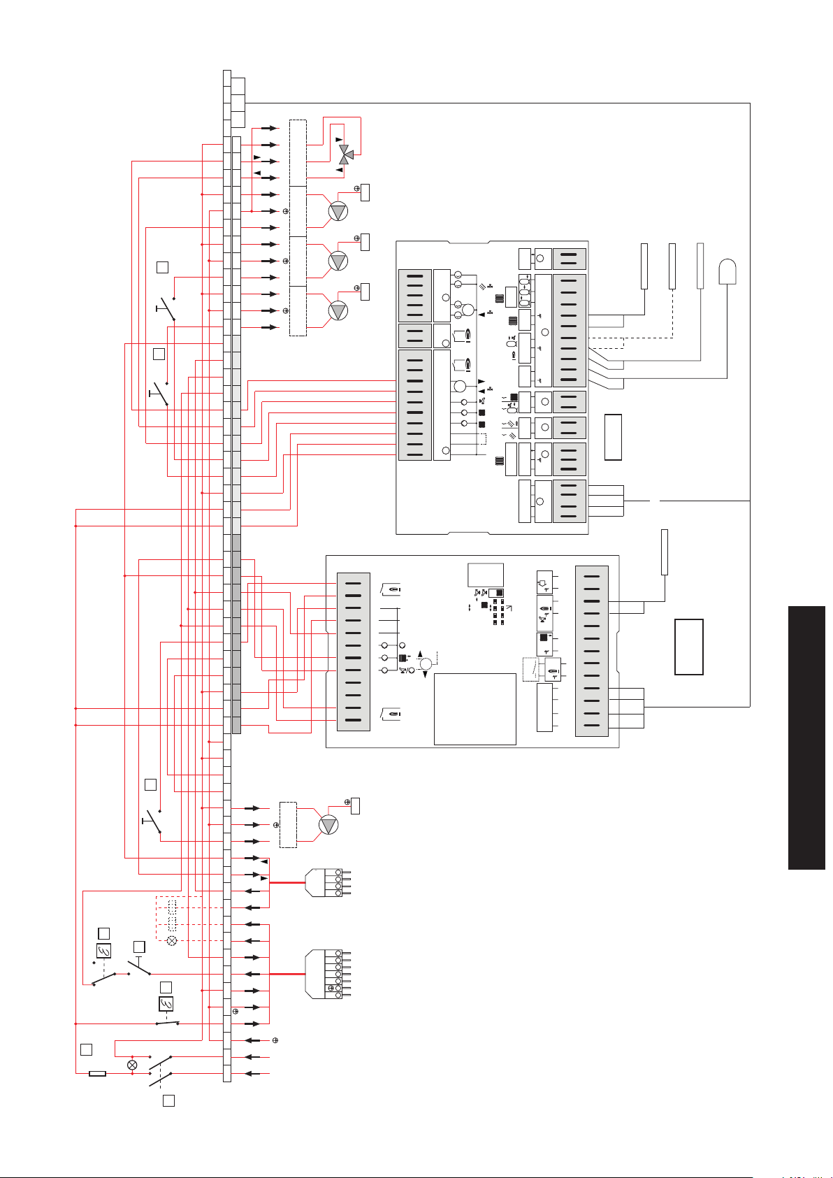
20
Ipz1
Can bus
mix. zona 2
mix. zone 2
valve contactor
teleruttore valvola
535047
boiler
storage tank
pump contactor
teleruttore pompa
21
Ipz2
zone 2
zona 2
pump contactor
teleruttore pompa
zone 1
zona 1
LLLL1 L2NNNN
pump contactor
teleruttore pompa
PbPz2Pz1
+-
VII
eBUS
0- 10V
A11
1
2
1
VIII IVA1 A2 A3 A4 A5 A6 A7 A8 A9 A10
23456718910 2345
n
3 4
2
1
FBR
31
1
M
1 2
2
1
M
2
VF
I
T3 T4
1
KF/SPF
4 3 2 1
2
-
FBR
31
F9 F8 F6 F5 F1F2F3
AF
1
VF
V
SPF
2
VIII
1
PT1000
Licht
0-10V
III
21 2121 4321876510 921
3
F17 F15 F14 F13 F12 F11
IMP
T1 T2
2
2
1
L1 L1'
N
SONDA DI MANDATA
VALVOLA MISCELATRICE 2
FLOW PROBE
MIXING VALVE 2
E8.5064
SONDA DI COLLETTORE O DI CALDAIA
SE È PRESENTE UNA SOLA CALDAIA
EVENTUALE
SONDA BOILER
(IF INCLUDED)
STORAGE TANK PROBE
MANIFOLD OR BOILER PROBE
IF THERE IS ONLY ONE BOILER
SONDA ESTERNA
EXTERNAL PROBE
H
IX
Bus
~50Hz 230V
+- L
43 21
33
2
1
16
F1 (max 6A)
Te (0°-100°C)
c
18
Ib
19
Ip1
BC
A
35
Ts (11°C)
c
Ig
14
AF
KF1
SPF
VF
+
CAN-BUS
-
L
H
25
24
23
22
21
20
19
KF2
16
15
14
13
T4
12
2
T3
11
N
10
L1
9
L1’
8
1
7
6
2
5
5K NTC
min
+
40
OFF
65°C
1K PTC
60
fix
fix 24h
N
M
4
3
T1
2
1
1
T2
16
Pr
contactor
teleruttore
LN
Recirculation pump
White
Black
Bianco
Nero
Marron
Brown
Blu
Blue
Grigio
Grey
Rosso
Red
Bianco
White
Marron
Brown
Blu
Blue
Nero
Black
Pompa ricircolo
T8
T7
T6
STAGE 2
C
2° STADIO
STAGE 1
1° STADIO
B5
B4
S3
T2
T1
NL1
ALLA PRESA A 4 POLI
DEL BRUCIATORE
TO THE 4-POLE SOCKET
OF THE BURNER
ALLA PRESA A 7 POLI
DEL BRUCIATORE
TO THE 7-POLE SOCKET
OF THE BURNER
T8T7T6B5
2
LNT1 S3T2 B4
SONDA DI CALDAIA
BOILER PROBE
Lago Basic
0201RV1
Technical features and dimensions
N
123456789101112131415161718192021222324252627282930313233343536373839404142434445464748495051525354555657H L- +
L1
230V ~ 50Hz
POWER SUPPLY
ALIMENTAZIONE
Ph Phase (230V ~50Hz)
N Neutral
F1 General fuse (max 4A)
IG Main switch with indicator light
Ib Burner switch
Te Working thermostat (0°C÷90°C)
Ts Safety thermostat (100°C)
Ipz1 System pump zone 1 switch
Ipz1 System pump zone 2 switch
Pz1 System pump zone 1
Pz2 System pump zone 2
Pb Storage tank pump
Pr Recirculation pump
Ip1 Main ring pump switch
Mix zone 2 Mixing valve zone n° 2
31

3.18 - PROGRAMMING THE
HEATING CONTROLLERS
For that which concerns adjustment or programming of the heating
controllers, see the instruction manual attached to the individual
heating controller.
The following are the default parameters which cannot be modified.
As far as parameters which can be programmed by the user ac
cording to his requirements, see the system manager instruction
book.
PARAMETERS PROGRAMMABLE BY TECHNICIAN AND PROTECTED BY ACCESS CODE FOR
HEATING CONTROLLER type E8.5064
INSTALLATION
Default Individual valuesValue rangeDescription
CODE NUMBER ENTRY
CODE NUMBER (variation) 0000
BOILER BUS ID ----
BUS ID 1
BUS ID 2
AF SUPPLY 01 (ON)
BUS CONNECTION 01
BUS SUPPLY 01 (ON)
TEMPERATURE MASTER
MAX-T HS1 MAX T-HEADER
MIN-T HS1 MIN T-HEADER
MAX-T HS2 95 °C
MIN-T HS2 10 °C
VOLTAGE CURVE 11
CURVE 11-U2 0V
CURVE 11-U2 10V
CURVE 11-T1 0 ℃
CURVE 11-T2 100 °C
CURVE 11-UA 0V
T-WARM-UP 10
MINIMUM LIMIT
HYSTERESIS
HYSTERESIS TIME
BOILER DETECTED
OUTPUT LEVEL * see note
NEW CONFIGURATION
MINIMUM MODULATION CASCADE 00
DHW LEVELS 00
CONTROL VARIANCE VIEW
NOMINAL OUTPUT INDEX VIEW
SWITCH VALUE VIEW
BLOCK TIME VIEW
MAXIMUM BOILER TEMPERATURE 85
BOILER DYNAMICS UPWARD 30K
BOILER DYNAMICS DOWNWARD 20K
RESET TIME 50
MODULATION MAX 80%
MODULATION MIN 50%
MIN MODULATION HS 0%
IGNITION MODULATION INDEX 80%
BOILER SEQUENCE 1 12345678
BOILER SEQUENCE 2 87654321
0000 - 9999
0000 - 9999
......, 01 - 08
(00), 01 - 015
(00), 01 - 016
00,01 (off/on)
0.01
00,01 (off/on)
00, 01 (OFF / ON)
30 °C - 110 °C
10 °C - 80 °C
30 °C - 110 °C
10 °C - 80 °C
0 - 11
0.00-10.00V
0.00-10.00V
00 - 120 °C
00 - 120 °C
0.00-10.00V
10 °C - 85 °C
00, 01, 02
2K - 20K<P>
00 - 30 min
VIEW ONLY
00 - 1000kW
00,01 (off/on)
00 - 100
00 - 08
(K)
0 - 100%
(-99) - 0 - (99)
REMAINING (min)
50 - 110°C
20 - 500K
20 - 500K
5 - 500
0% - 100%
0% - 100%
0% - 100%
40% - 100%
----
----
01
02
01 (ON)
95 °C
10 °C
00
5
00 min
-
32

Default Individual valuesValue rangeDescription
SEQUENCE MODE 01
SEQUENCE CHANGE
CYCLE BLOCK
HYSTERESIS BURNER 2
BOILER COOLING FUNCTION
BOILER COOLING TEMPERATURE
HS 1 TYPE
HS 1 BUS
HS 2 TYPE
HS 2 STORAGE TANK
PUFFER
SCREED
SCREED PROGRAM
* For only one modulating boiler, set the first stage value of the boiler at 1, in the second leave the dashes.
For two modulating boilers in cascade, set the first stage value at 1 for both boilers and in the second leave the dashes.
All other boiler stages must be disabled.
** See E8.5064 heating controller instruction manual
01 - 06
10 - 800 HOURS
00 min - 30 min
2K - 20K<P>
00 - 01
30°C - 120°C
00 - 06
00 - 04
00 - 05
01 - 03
01 - 01 - 02
00, 01 (OFF - ON)
** see note
200 HOURS
00 min
2K
00
95
06
04
00
00
00
00 OFF
DOMESTIC HOT WATER PRODUCTION
Default Individual valuesValue rangeDescription
CHARGE PUMP 01 (ON)
PARALLEL PUMP RUNNING 01
T DHW 20K
DHW HYSTERESIS 5 degrees
DHW FOLLOWUP 00 min
THERMOSTAT INPUT 00 OFF
THERMOSTAT FUNCTION 00 OFF
LOADING 00 OFF
RETURN
HEATING CIRCUIT FUNCTION 0
PUMP FUNCTION 0
MIXER OPEN ----
MIXER CLOSED ----
MAX FLOW TEMPERATURE 95 °C
MIN FLOW TEMPERATURE 30 °C
FROST PROTECTION TEMP 0 ℃
OUTSIDE TEMP DELAY 0.00
HEATING SLOPE DISTANCE 5 °C
MANDATORY REDUCTION 01
00 - 01 (OFF / ON)
00 , 01, 02, 03
00K - 50K
5K - 30K
00 min - 30 min
00, 01 (OFF / ON)
00, 01 (OFF / ON)
00, 01 (OFF / ON)
Exit level using
HEATING CIRCUIT 1
Default Individual valuesValue rangeDescription
00 - 04
00 - 03
5 - 25
5 - 25
20 °C - 110 °C
10 °C - 110 °C
(-15)°C - (5)°C
0:00 - 24:00
00K - 50K
00 - 01 (OFF / ON)
Technical features and dimensions
RETURN
Exit level using
33

HEATING CIRCUIT 2
°C
OK
1
2
1
2
>1s
+
°C
°C
°C
BUS ID 1/2/11/Mod
Run
2
1
Default Individual valuesValue rangeDescription
HEATING CIRCUIT FUNCTION 0
PUMP FUNCTION 0
MIXER OPEN ----
MIXER CLOSED ----
MAX FLOW TEMPERATURE 45 °C
MIN FLOW TEMPERATURE 10 °C
FROST PROTECTION TEMP 0 ℃
OUTSIDE TEMP DELAY 0.00
HEATING SLOPE DISTANCE 5 °C
MANDATORY REDUCTION 01
00 - 04
00 - 03
5 - 25
5 - 25
20 °C - 110 °C
10 °C - 110 °C
(-15)°C - (5)°C
0:00 - 24:00
00K - 50K
00 - 01 (OFF / ON)
RETURN
Exit level using
SOLAR M/F
Default Individual valuesValue rangeDescription
MF (1-4) FUNCTION 00,00,01,02
MF (1-4) T- NOM 30°C
MF (1 - 4) HYSTERESIS 5°C
F 15 FUNCTION 0
RETURN
Exit level using
00 - 26
00 - 03
5 - 25
5 - 25
PARAMETERS PROGRAMMABLE BY TECHNICIAN FOR HEATING CONTROLLER
Lago Basic 0201 RV 1
1
2
3
1 1) Switch selector to burner (1)
2) Press ok (2)
3) Turn the knob (3) until mm appears on the display (modulating burner)
4) Press ok (2)
2 1) Switch selector (1) to mixer valve symbol
2) Press ok (2)
3) Turn the knob (3) and set the burner damper time (time necessary to switch from minimum output to maximum output)
4) Press ok (2)
3 1) Switch the selector (1) to BUS ID
2) Press ok (2)
3) Turn the knob (3) until the number 1 appears on the display (boiler ID)
4) Press ok (2). Turn the knob 1 back to pos. RUN.
34

3.19 - HYDRAULIC AND ELECTRICAL
CALDAIA TERNOx
1
M
13
14
15
16
19
20
21
22
23
24
25
+
-
L
CAN-BUS
H
1
3
6
7
8
9
10
11
12
AF
VF
KF2
KF1
SPF
2
N
L1’
N
L1
T3
T4
2
+
T2
T1
1
4
5
2
1K PTC
65°C
5K NTC
60
OFF
min
40
fix 24h
fix
Lago Basic
0201RV1
Pz1 Pz2
SYSTEM CONNECTION
The following figures show the typical layout of the connection
of the boiler to the heating system consisting of 2 zones one of
which controlled by a motorised mixing valve.
DHW production can also be managed.
ROOM PROBE 1
(FBR1)
FLOW PROBE 2
(VFAS)
STORAGE TANK PROBE
(SPFS)
BOILER PROBE
(KFS)
EXTERNAL PROBE
(AFS)
ROOM PROBE 2
(FBR1)
Remember that TERNOX 2S boilers operate with forced circulation.
Key:
Pr = recirculation pump
VM2 = zone mixing valve
Pz1 = direct zone heating system pump
Pz2 = mixed zone heating system pump
VE = expansion vessel
IR1 = direct zone heating system distribution
IR2 = mixed zone heating system distribution
Ps = domestic water recirculation pump
Pb = DHW production charge pump
SPFS = storage tank probe
KF = boiler probe (E8 heating control)
KF1 = boiler probe (Lago Basic heating control)
VFAS = flow probe 2
TERNOx BOILER
DOMESTIC HOT WATER
PRODUCER
Technical features and dimensions
35

LNT1 S3T2 B4
B5
T6
T7
T8
ALLA PRESA A 4 POLI
DEL BRUCIATORE
2° STADIO
12
3
4
56
7
8910
11 12
13
14
15 16
17
18 19 20
21 22
23
24
25 26
27
28 29 30 31 32 33 34 35 36 37 38 39 40
41 42
43
44
45 46
47
48 49 50 51 52 53 54 55 56 57
HL
-
+
NL1
T1
T2
S3
B4
ALLA PRESA A 7 POLI
DEL BRUCIATORE
1° STADIO
T8T7T6B5
ALIMENTAZIONE
230V ~ 50Hz
L1
N
Nero
Blu
Marron
Bianco
Rosso
Grigio
Blu
Marron
Nero
Bianco
C
CALDAIATERMAX
1
M
13
14
15
16
19
20
21
22
23
24
25
+
-
L
CAN-BUS
H
1
3
678
9
10
11
12
AF
VF
KF2
KF1
SPF
2
N
L1’NL1
T3
T4
2
+
T2
T1
1
452
1K PTC
65°C
5K NTC
60
OFF
min
40
fix 24h
fix
Lago Basic
0201RV1
2 3 4 5 6 71 8 9 10
2 3 4 5
1
~50Hz 230V
2
1
VI
II
IV
A1 A2 A3 A4 A5 A6 A7 A8 A9 A10
A11
1
L1 L1'
1
2
M
M
2
T1 T2
2
T3 T4
1
1
2
3
4
2
2
n
N
2
4 3 2 1
3
2 1 2 1 2 1
4 3 2 18 7 6 510 9
2 1
+ - L
Bus
H
PT1000
VF
AF
KF/SPF
VF
IX
III
2
3 1
FBR
-
IMP
Licht
0-10V
SPF
eBUS
0- 10V
VIII
V
F17 F15 F14 F13 F12 F11
I
VII
+-
F9 F8 F6 F5 F1F2F3
1
4
3
2
1
1
1
1
3 1
FBR
E8.5064
Pz1 Pz2
230V - 50 Hz
POWER SUPPLY
PRODUCER
DOMESTIC HOT WATER
36
White
Black
Brown
Blue
Grey
Red
White
Brown
Blue
Black
POWER SUPPLY
STAGE 2
STAGE 1
TO THE 4-POLE SOCKET
TO THE 7-POLE SOCKET
OF THE BURNER
OF THE BURNER
TERMAX BOILER
ROOM PROBE 1
(FBR1)
FLOW PROBE 2
(VFAS)
STORAGE TANK PROBE
(SPFS)
BOILER PROBE (KF)
EXTERNAL PROBE (AFS)
ROOM PROBE 2
(FBR1)
NOTE: With absorption beyond 4A, place adequate contactors between the panel board and the loads

°C
OK
1
2
1
2
>1s
+
°C
°C
°C
BUS ID 1/2/11/Mod
Run
2
1
31
42
11
41
12
13
32
3.20 - CASCADE PANEL BOARD
The main switch 11 powers the board and the equipment connected to it.
The switches 12 and 13 control the burner and P1 pump if the
boiler operates in cascade.
The thermostat adjusts the working temperature of the boiler
2: to achieve this, the thermostat must be placed at maximum
full-scale pos. 32 .
Modulation of the burner will be managed by heat control.
The electric power line of the boiler's control board must have a
switch with protective fuses.
11 Main switch with indicator light
12 Burner switch
13 P1 C.H. pump switch (cascade)
32 Working thermostat
41 General fuse
42 Thermometer
31 Safety thermostat
For use of the panel board, see the system manager instruction manual.
As far as the practical connection and operating diagrams are concerned,
see the documentation supplied inside the panel board.
The boiler probe is included in the supply.
Technical features and dimensions
37

°C
OK
1
2
1
2
>1s
+
°C
°C
°C
BUS ID 1/2/11/Mod
Run
2
1
PARAMETERS PROGRAMMABLE BY TECHNICIAN FOR HEATING CONTROLLER
Lago Basic 0201 RV 1 ON BOILER N°2
1
2
3
1 1) Switch selector to burner (1)
2) Press ok (2)
3) Turn the knob (3) until mm appears on the display
4) Press ok (2)
2 1) Switch selector (1) to mixer valve symbol
2) Press ok (2)
3) Turn the knob (3) until the number 15 appears on the display (burner servomotor time)
4) Press ok (2)
3 1) Switch the selector (1) to BUS ID
2) Press ok (2)
3) Turn the knob (3) until the number 2 appears on the display (boiler ID)
4) Press ok (2). Turn the knob 1 back to RUN.
38

Ps
DELL’IMPIANTO
M
R
VE
SPF
CALDA SANITARIA
PRODUTTORE ACQUA
DOMESTIC HOT
Pb
WATER PRODUCER
IR/BT
Pz2
VF
Vmix2
KF
IR/AT
OF THE SYSTEM
HYDRAULIC SEPARATOR
Pz1
P1
FOR PERFECT BALANCING
PER IL PERFETTO BILANCIAMENTO
EVENTUALE SEPARATORE IDRAULICO
Ps = domestic water recirculation pump
P1 = circulation pump
Pb = DHW production charge pump
SPF = storage tank probe
KF = E8.5064 heat control boiler probe
KF 1= Lago Basic 0201 RV 1 heat control boiler probe
VF = flow probe
AF = external probe
PANNELLO STRUMENTI
CASCATA
PANEL BOARD
CASCADE
+
°C
°C
°C
-
Run
BUS ID 1/2/11/Mod
2
1
°C
1
OK
1
2
2
>1s
13
12
32
41
42
11
31
can bus
F
Solare/M
II
isc.
Circuito r
I
isc.
Circuito r
Acqua Calda
Im
pianto
21.0
Tecnico
po
r.Tem
Prog
Utente
.
Visual Inf
20
e
acanz
a/V
Data/Or
vizio
Ser
+
°C
°C
°C
-
Run
BUS ID 1/2/11/Mod
2
1
°C
1
OK
1
2
2
>1s
35
34
33
18 19 20 21 22 23
14 15 16 17
PROBE
EXTERNAL (AF)
SONDA
ESTERNA (AF)
3.21 - HYDRAULIC AND ELECTRIC SYSTEM CONNECTION WITH BOILERS IN CASCADE
The figure shows the typical layout of the connection of the boiler to the heating system consisting in 2 boilers in cascade serving 1 high temperature zone + 1 low temperature
zone controlled by a motorised mixing valve + domestic hot water production.
Boiler n°1 is equipped with a MASTER panel board, boiler n°2 with a CASCADE panel board.
PANNELLO STRUMENTI
MASTER
PANEL BOARD
MASTER
TERNOX 2S 2 BOILER
CALDAIA TERNOX 2S 2
Technical features and dimensions
P1
R
VE
M
TERNOX 2S 1 BOILER
CALDAIA TERNOX 2S 1
Key:
M = flow
Rat = HIGH temperature return (NOT USED)
Rbt = LOW temperature return
Vmix2 = zone mixing valve (motorised)
Pz1 = HIGH TEMPERATURE zone heating system pump
Pz2 = LOW TEMPERATURE zone heating system pump
VE = expansion vessel
IR/AT = HIGH TEMPERATURE heating system distribution
IR/BT = LOW TEMPERATURE heating system distribution
39

The panel boards of the XC-K boilers (in cascade) automatically
switch the burners off when the temperature in the boiler reaches
the value set on the heating controller.
They also manage the pump to fill a storage tank for DHW
production.
The heating systems are managed automatically based on the
data detected by the boiler, external, ambient and flow probes.
The high temperature zone C.H. pump is made ready for operation by the control switch pos. 20 of the MASTER board, and
will only switch off when the temperature set on the heating
controller has been reached.
The low temperature zone C.H. pump is made ready for operation
by the control switch pos. 21 of the MASTER board, and will only
switch off when the temperature set on the heating controller
has been reached.
The storage tank charge pump for DHW production switches on
automatically and will only switch off when the temperature set
on the heating controller has been reached.
The panel is set up to manage the modulating burners.
With this system configuration, the heating controller is capable
of checking:
- direct zone system; the control unit commands the C.H. pump.
The room temperature is controlled by the programming
curves set in the heating controller;
- one zone system with motorised mixing valve: the flow probe
(downstream the mixing valve) must be fitted; the control unit
commands the C.H. pump and the mixing valve. The room
temperature is controlled by the programming curves set in
the heating controller;
- DHW production through storage tank;
- anti-legionella function with increase of water temperature
in storage tank (function not enabled in factory, but can be
enabled by customer).
For practical connections, both electrical and of the probes, see the diagrams supplied with the
MASTER and CASCADE panel boards.
40

3.22 - COMMISSIONING
3.22.1 - Preliminary checks
Commissioning must be done by professionally qualified personnel. Unical will not be
held liable for damage to persons, animals
or objects due to failure to comply with the
above instruction.
After connecting the hydraulic and electrical system and the fuel line to the boiler, and before starting up the boiler, it is advisable
to check the following:
Have all the hydraulic and electrical systems and the safety devices and fuel been connected in compliance
with the domestic and local laws in force?
Are the expansion vessel and the safety valve (when applicable) connected correctly and cannot be shut off?
Are the bulbs of the operating, safety, minimum thermostats and that of the thermometer inserted in their
conduits?
Are the control and safety devices working and configured correctly?
Are the refractory coverings intact?
Are the combustion air intake line and the flue gas evacuation line compliant with the applicable standards in
force?
does the gas used (models with gas burner) correspond to boiler calibration?
is the fuel supply system sized according to the capacity required by the boiler?
is it equipped with all safety and control devices required by the standards in force?
are the mains voltage and frequency compatible with the burner and the electrical equipment of the boiler?
is the burner assembled according to the instructions in the manufacturer's manual?
has the burner blast tube infill been performed correctly?
Is the system full of water and does not contain any air?
Are the drain valves closed and the system cut-off devices fully open?
is the gas supply cock open (models with gas burner)?
has gas leakage been checked (models with gas burner)?
Is the outside main switch ON?
Is the pump/are the pumps working correctly?
has the system been checked for water leaks?
Are the ventilation conditions and minimum distances to perform any maintenance guaranteed?
Technical features and dimensions
Has the operator been trained and has the documentation been supplied?
Please tick the operations performed
41

3.22.2 - Ignition and extinction
Ignition
When the checks indicated in the previous paragraph are successful, the burner can be commissioned by a technician qualified and acknowledged by the Manufacturer of the burner.
The technician takes on all responsibility regarding calibration
within the declared and approved output range of the boiler.
After having opened the fuel shut-off valves and made sure
there are no leaks in the adduction circuit, set all switches at
ON.
The burner is now ready for commissioning and adjustment,
performed solely by the above-mentioned technician.
During commissioning, you must check that the door, the burner flange and connections with the chimney are airtight and that
there is a slight negative pressure at the base of the flue.
The fuel flow rate must correspond to the plate data of the boiler. It must by no means exceed the maximum declared nominal
output value.
The flue gas temperature must never drop below 160°C.
Extinction
- Set the operating thermostat at minimum.
- Disconnect power to the burner and close the fuel supply.
- Leave the pumps running until they are stopped by the mini-
mum thermostat.
- Disconnect power to the electric panel.
3.23 - ADJUSTING THE BURNER
The following instructions are intended exclusively for service personnel authorised by the
manufacturer of the burner.
Burner calibration and preliminary operations are described in
the burner's instruction booklet.
Gas-fired burners are equipped with a gas valve with which the
flow rate can be determined: upon commissioning the actual
thermal flow rate must always be controlled by means of the
counter on the main piping, making sure it is not below the
minimum value on the data plate of the boiler.
When the burner is adjusted properly, the following values should
be obtained, measured at the chimney by a specific analyser:
for diesel oil with max visc. 1.5°E at 20°C:
1)
- CO2 ~ 12÷13%
- Bacharach flue gas index ‹1
- Flue gas temperature ~ 190÷210 °C
2) with natural gas:
- CO2 ~ 9÷10%
- Flue gas temperature ~ 180÷200°C
(values for boiler cleaned with water at ~ 70°C).
The flow rate of the fuel should be adjusted to the actual requirement of the system without, on the one hand, exceeding
the indicated flue gas temperature and on the other, without
dropping below 160°C.
42

3.24 - CHECKS DURING AND AFTER
COMMISSIONING
When the appliance has been commissioned, check that it
performs a shutdown and subsequent ignition:
- by modifying the boiler thermostat calibration;
- by intervening on the main switch of the panel board.
Check tightness of all the gaskets on the water and flue gas
side. They must be further tightened when hot to guarantee
perfect sealing.
This operation is crucial for the gasket of the
doors, of the burner plate and of the flue gas
casing so that toxic and dangerous combustion
fumes do not escape from the boiler room.
Then tighten them when hot to guarantee
perfect sealing.
3.25 - ALKALINE
OR “BOILING” WASH
This is a treatment carried out by specialised companies on
the new boiler.
It removes deposits consisting of residual oil, grease and metal
oxides caused by processing and assembly of the boiler.
If these substances are not eliminated, corrosion is caused due
to the obstruction of the formation of a passivation coating on
surfaces exposed to water.
Execution of alkaline wash:
- Fill the boiler with water.
It is also very important to check sealing of the boiler/chimney
fitting for the reasons expressed above.
It is also extremely important to progressively tighten the gasket
of the railing and manhole of the generator as the temperature
increases for perfect sealing: otherwise the first time it leaks,
the gasket would need to be replaced.
Check that the appliance fully stops when acting on the main
switch of the system.
After all these conditions have been met, the burner must
be properly calibrated at the maximum output allowed by the
boiler, analysing the flue gas to achieve correct combustion and
as few polluting emissions as possible.
As the pressure of the water in the system increases during
operation, make sure that its maximum value does not exceed
the design pressure of the boiler.
- Instruments (pressure switch, pressure gauge etc.) must be
excluded before starting the wash.
- Introduce 0.3 to 1% of caustic soda, sodium carbonate or
trisodium triphosphate into the total content of the water.
- Specific surfactants must be added to these substances
ranging from 0.05 to 0.15% of the total content of the water.
- Switching on the burner, bring the water to a temperature of
80-90°C and have it circulate in the boiler for 12-14 hours.
- Slowly empty the content and simultaneously introduce cold
water to rinse it properly.
3.26 - BOILER SHUTDOWN
To shut down the boiler for a long period, proceed as follows:
- perform the preservation procedure of the water side, which
can be wet or dry;
- turn off the main switch of the electric panel and disconnect
the power supply;
- close the fuel shut-off valve;
- perform the flue gas side preservation procedure;
- protect all control, adjustment and safety devices from dust
and humidity.
"Wet preservation" entails completely filling the boiler and
adding preserving or neutralising products to the water.
Then the system must be sealed by closing all the shut-off
valves.
This type of preservation is not recommended if there is a risk
of freezing.
"Dry preservation" requires emptying the boiler.
Open the railing, completely dry the inside of the boiler by
blowing air and insert highly hygroscopic substances (e.g.
quick lime).
Close all the shut-off valves and the railing, thus sealing the
generator.
Preservation of the flue gas side is performed as follows: open
the inspection doors, remove the burner and disassemble the
cap, clean all surfaces from soot (which could contain sulphur
which becomes sulphuric acid when it becomes moist) and
insert highly hygroscopic substances (e.g. quick lime) into the
furnace and flue gas casing.
Hermetically close all the inspection doors, put the burner cap
and burner back in place.
Maintenance instructions
43

4
INSPECTIONS AND
MAINTENANCE
Routine maintenance is essential in the interest of the safety, efficiency and durability
of the appliance.
All maintenance must be carried out by qualified personnel.
Yearly maintenance of the appliance is mandatory in compliance with Laws in force.
Failure to perform Inspections and Maintenance can entail material and personal
damage.
All cleaning and maintenance operations
must be preceded by closing the fuel supply,
after having disconnected electricity.
In order to make the most of the boiler,
you should properly clean the combustion
chamber, smoke pipes and smoke chamber.
IMPORTANT NOTE
Before opening the furnace door, it is necessary
to take the following safety measures:
- Close the fuel supply (diesel oil or gas) to the
burner.
- Cool the boiler off by having water circulate
and then disconnect electrical power.
- Place a sign on the boiler with the following
text: DO NOT USE, BOILER MAINTENANCE
UNDERWAY, OUT OF SERVICE.
Inspections help to determine the actual status of
the appliance and to compare it with the nominal
status. This is done through measuring, controls
and observation.
Maintenance is required to eliminate any differences between the actual status and the nominal status. This is normally done by cleaning, setting and
replacing individual components subject to wear.
Maintenance intervals and their extent are determined by a specialist based on the status of the
appliance ascertained through inspection.
Routine maintenance
Maintenance must be established based on the fuel used, the
number of ignitions, the features of the system, etc. Therefore it
is not possible to establish beforehand the frequency of maintenance.
The following cleaning intervals are recommended depending
on the type of fuel:
- Gas-fired boilers: once a year.
- Diesel oil-fired boilers: twice a year.
- Fuel oil boilers: every 300 hours of operation.
In any case, local standards regarding maintenance must be
respected.
During routine maintenance operations, the tube bundle and
furnace must be brushed.
Remove deposits built up in the flue gas casing by opening the
inspection doors.
For more energetic actions, remove the rear smoke chamber
and replace the flue gas gasket if worn. Check that the condensation discharge is not obstructed.
Check that the control and measurement devices serving the
generator work properly. On this occasion, the amount of recirculation water used must be detected. After having analysed
the water, perform preventive descaling.
Calcium and magnesium salts dissolved in the water with repeated top ups give rise to deposits in the boiler and cause the
sheet-metal to overheat, with possible damage which cannot
be attributed to the materials or manufacturing, and therefore is
not covered by warranty.
After having performed maintenance and cleaning operations
and subsequent ignition, check the seals of the door and of the
smoke chamber. If any combustion products leak, replace the
relative gaskets.
The operations carried out must be written in the boiler room
booklet.
Extraordinary maintenance
Extraordinary maintenance at end of season or for long idle
periods.
All the operations described in the previous chapter must be
carried out, plus:
- After cleaning the flue gas circuit, pass a rag soaked with a
solution diluted with caustic soda. After leaving it to dry, repass all the surfaces with a rag soaked in oil.
- It is recommended to place hygroscopic substances inside
the furnace (quick lime, silicon gel in small containers) and to
close it hermetically so that no air enters.
- Do not empty the system and the boiler.
- Protect screws, nuts and pins of the door with graphite
grease.
The operations carried out must be written in the boiler room
booklet.
44

Inspection and maintenance instructions
To assure long-term functioning of your appliance
and to avoid altering its approved status, only
original Unical spare parts must be used.
Before proceeding with maintenance, always perform the following operations:
• Disconnect the electric mains switch.
• Isolate the appliance from the electric mains by means of
an isolated device with a contact opening of at least 3 mm
(e.g. safety devices or power switches) and make sure that
it cannot be re-connected accidentally.
• Close the gas shut-off valve upstream the boiler (where
present).
• Close any shut-off valves on the heating flow and return
pipes.
Boiler body maintenance
Danger!
Before performing any maintenance, make
sure the boiler and its components have
cooled down.
Disconnect the boiler from the electric mains
and shut the gas supply (if any) to the appliance.
Attention!
Before cleaning the boiler body, protect the
panel board against any water sprays.
After having completed all maintenance work, always perform
the following operations:
• Open the heating flow and return pipes.
• If necessary, restore the heating system pressure until it
reaches the static pressure relative to the highest point of
the system.
• Open the gas shut-off valve (where present).
• Reconnect the appliance to the electric mains and engage
the switch.
• Check tightness of the appliance on the gas side (where
present) and on the water side.
• Vent the heating system and restore pressure if necessary.
Should you decide to temporarily deactivate the boiler, you
must:
a) intercept the supplies: electric, water and fuel;
b) empty the water system if antifreeze is not used.
Check condition of gaskets and insulation fibres
The insulation fibre of the door can show cracks
after a short time of operation; this however does
not reduce its insulation capacity nor jeopardise
its lifespan. Check the condition of the seal gasket which must not show signs of deterioration;
if so, it must be replaced, using only original
spare parts.
Check the condition of the smoke chamber inspection cover
gasket.
Replace it if worn, using only original spare parts.
Once a year, at the end of the heating season, the boiler must
receive a general cleaning.
Before performing any maintenance, make sure that all the
precautions referred to in the previous point have been taken.
To proceed with maintenance you must:
- disconnect power by acting on the main switch;
- remove the burner, which could be overhauled at the same
time;
- open the furnace door to access the combustion chamber;
- remove the smoke chamber access door;
- brush the smoke ducts energetically to remove any trace of
filth.
Maintenance of burner
Burner maintenance must be carried out by personnel authorised
by its manufacturer (or else the warranty shall be terminated).
Checking ignition electrode
Burner maintenance must be carried out by personnel authorised
by its manufacturer (or else the warranty shall be terminated).
Maintenance instructions
45

TROUBLESHOOTING
The following are the most common causes of
faults and their solutions.
FAULT:
The burner does not switch on.
FAULT:
The burner switches on regularly but shuts down immediately.
FAULT:
Difficulty in adjusting the burner and/or lack of efficiency.
FAULT:
The burner is easily soiled with soot.
FAULT:
Smell of gas and/or unburnt products.
SOLUTIONS:
- check the electrical connections;
- check the regular flow of fuel;
- check that the fuel feeding system is intact and clean, and that it is deaerated;
- check that ignition sparks are performed regularly and operation of the burner appliance;
- check triggering of the boiler safety thermostat with manual rearming;
- check calibration of the adjustment thermostat.
SOLUTIONS:
- check flame detection, air calibration and operation of the burner appliance.
SOLUTIONS:
- check that the burner, boiler, boiler/chimney duct and chimney are clean;
- check sealing of the flue gas circuit (inspection doors, burner plate, flue gas casing,
boiler/chimney fitting);
- check the regular flow of fuel and the real output supplied by the burner;
- check for any scales and perform a chemical wash.
SOLUTIONS:
- check burner adjustment (flue gas analysis);
- check the amount of fuel;
- check clogging of the chimney and cleanliness of the burner air path (dust).
SOLUTIONS:
- check sealing of the fuel supply system (if gas);
- check sealing of the flue gas circuit (inspection doors, burner plate, flue gas casing,
boiler/chimney fitting);
- check that the rubber holder on the flame warning light is connected to the air socket of the burner or if it is plugged.
FAULT:
The boiler does not reach operating temperature.
FAULT:
The boiler is at operating temperature but the heating system is cool.
FAULT :
The safety thermostat triggers.
FAULT:
The boiler safety valve triggers.
FAULT:
Overheating of members due to lack of water in boiler.
FAULT:
Water on floor near flue gas casing (condensation).
SOLUTIONS:
- check that the flue gas side and water side of the boiler are clean;
- check coupling, adjustment and efficiency of the burner;
- check the temperature set on the thermostats and their correct operation;
- check positioning of the thermostat probes;
- make sure that the boiler has sufficient output for the system.
SOLUTIONS:
- check that the system is deaerated;
- check that the circulation pumps work properly.
SOLUTIONS:
- check that electric wiring is correct;
- check positioning of the thermostat probes;
- check the calibration of the thermostats and their correct operation.
SOLUTIONS:
- check the pre-load pressure of the system;
- check that the expansion vessel is sized correctly;
- check that the safety pressure valves are calibrated correctly.
SOLUTIONS:
- switch off the burner, do not introduce water or open the inspection doors and wait
for return to room temperature before performing any operation.
SOLUTIONS:
- check the correct positioning of the probes, correct operation and calibration of the
boiler adjustment thermostat (minimum 60°C);
- check that the exhaust in the flue gas casing is connected to a collection recipient;
- check that the anti-condensation pump (if present) works correctly and is properly
adjusted;
- check that the water temperature returning from the system is no less than 50 °C.
46

47

www.unical.eu
edition 08/14
st
00335304 - 1
46033 casteldario - mantova - Italy - tel. +39 0376 57001 - telefax +39 0376 660556
AG S.p.A.
info@unical-ag.com - export@unical-ag.com - www.unical.eu
It reserves the right to modify its products as deemed necessary or useful, without jeopardising their essential features.
Unical will not be held responsible for possible inaccuracies due to transcription or printing errors.
 Loading...