

STILE 27
00334578 - 05/13
rev. 0
INSTRUCTIONS
FOR INSTALLATION,
MAINTENANCE
AND USE

General information
TABLE OF CONTENTS
1 GENERAL INFORMATION ............................................................................................................................................................................ 4
1.1 Symbols used in the manual ........................................................................................................................................................................ 4
1.2 Appropriate use of appliance ....................................................................................................................................................................... 4
1.3 Water treatment ............................................................................................................................................................................................ 4
1.4 Information for user ...................................................................................................................................................................................... 4
1.5 Safety warnings ............................................................................................................................................................................................ 5
1.6 Technical data plate ...................................................................................................................................................................................... 5
1.7 General warnings ......................................................................................................................................................................................... 6
2 TECHNICAL FEATURES AND DIMENSIONS ........................................................................................................................................... 7
2.1 Technical features ........................................................................................................................................................................................ 7
2.2 Dimensions and hydraulic connections ...................................................................................................................................................... 7
2.3 Technical data ............................................................................................................................................................................................. 11
2.4 Supply..........................................................................................................................................................................................................11
2.5 Main components ....................................................................................................................................................................................... 12
2.6 General Information .................................................................................................................................................................................... 12
3 INSTALLATION INSTRUCTIONS ............................................................................................................................................................... 14
3.1 General warnings ...................................................................................................................................................................................... 14
3.2 Installation standards ................................................................................................................................................................................ 15
3.3 Packaging .................................................................................................................................................................................................. 16
3.4 Installation .................................................................................................................................................................................................. 16
3.5 Flue connection ......................................................................................................................................................................................... 17
3.5.1 Exhaust through external wall........................................................................................................................................................ 18
3.5.2 Exhaust through roof by means of traditional flue ........................................................................................................................ 19
3.6 Connecting heat stove to system ............................................................................................................................................................ 20
3.7 Filling the system....................................................................................................................................................................................... 20
4 ELECTRICAL CONNECTIONS .................................................................................................................................................................... 21
5 HEAT STOVE START-UP .............................................................................................................................................................................. 24
5.1 Commissioning .......................................................................................................................................................................................... 24
5.2 Initial lighting checks ................................................................................................................................................................................. 24
6 INSPECTION AND MAINTENANCE ........................................................................................................................................................... 25
6.1 Troubleshooting ......................................................................................................................................................................................... 28
7 PROGRAMMING SETTING ........................................................................................................................................................................... 29
7.1 Using the product ...................................................................................................................................................................................... 29
7.2 Remote control .......................................................................................................................................................................................... 30
7.3 Function of buttons ................................................................................................................................................................................... 32
7.4 Menu ........................................................................................................................................................................................................... 33
7.4.1 User menu ........................................................................................................................................................................................ 33
7.4.2 Menu 01 - set clock ........................................................................................................................................................................ 35
7.4.3 Menu 02 - set chrono ..................................................................................................................................................................... 35
7.4.4 Menu 03 - choose language........................................................................................................................................................... 39
7.4.5 Menu 04 - standby mode ............................................................................................................................................................... 39
7.4.6 Menu 05 - buzzer mode ................................................................................................................................................................. 39
7.4.7 Menu 06 - initial load ....................................................................................................................................................................... 39
7.4.8 Menu 07 - heat stove status .......................................................................................................................................................... 40
7.5 User operating mode ................................................................................................................................................................................ 41
7.5.1 Lighting STILE 27 ............................................................................................................................................................................. 41
7.5.2 Start-up............................................................................................................................................................................................ 41
7.5.3 Failed ignition ................................................................................................................................................................................... 41
7.5.4 Heat stove working......................................................................................................................................................................... 42
7.5.5 Changing room temperature setting .............................................................................................................................................. 42
7.5.6 Using external thermostat / chronothermostat............................................................................................................................. 42
7.5.7 Changing water temperature setting ............................................................................................................................................. 43
7.5.8 The room temperature reaches the set temperature (SET temperature) .................................................................................. 43
7.5.9 The water temperature reaches the set temperature (SET water temperature) ....................................................................... 44
7.5.10 Restarting after extinction having reached set room and/or water temperature ..................................................................... 44
7.5.11 Cleaning the brazier ..................................................................................................................................................................... 45
7.5.12 Heat stove extinction .................................................................................................................................................................... 45
7.5.13 Heat stove off ................................................................................................................................................................................ 46
7.5.14 Heat stove re-ignition ................................................................................................................................................................... 46
7.6 What happens if......................................................................................................................................................................................... 47
7.6.1 The pellet does not light ..................................................................................................................................................................47
7.6.2 Electric power is missing ................................................................................................................................................................ 47
7.7 Alarms ........................................................................................................................................................................................................ 48
7.7.1 Flue gas temperature probe alarm ................................................................................................................................................ 48
7.7.2 Flue gas overtemperature alarm ................................................................................................................................................... 48
2

General information
7.7.3 Failed ignition alarm......................................................................................................................................................................... 49
7.7.4 Extinction during working phase alarm ......................................................................................................................................... 49
7.7.5 Screw safety pressure switch alarm............................................................................................................................................. 49
7.7.6 General thermostat alarm .............................................................................................................................................................. 50
7.7.7 Flue gas intake fan fault alarm ....................................................................................................................................................... 50
7.8 Operational mode (technical menu)......................................................................................................................................................... 51
7.8.1 Submenu 08 - 01 - 01 ..................................................................................................................................................................... 53
7.8.2 Submenu 08 - 02 - 01 chimney type ............................................................................................................................................. 53
7.8.3 Submenu 08 - 03 database ............................................................................................................................................................ 53
7.8.4 Submenu 08 - 04 various settings ................................................................................................................................................. 53
7.8.5 Submenu 08 - 05 outputs test........................................................................................................................................................ 53
7.8.6 Submenu 08 - 06 factory settings ................................................................................................................................................. 53
7.8.7 Submenu 08 - 07 reset partial hours............................................................................................................................................. 53
7.8.8 Submenu 08 - 08 alarm reset ........................................................................................................................................................ 54
7.8.9 Submenu 08 - 09 counter memories ............................................................................................................................................. 54
7.8.10 Flue gas probe calibration ............................................................................................................................................................. 54
3
General information
Attention: this manual contains instructions for the exclusive use of the professionally qualified installer and/or
maintenance technician in compliance with current legislation.
The user is NOT qualified to intervene on the heat stove.
The manufacturer will not be held liable in case of damage to persons, animals or objects resulting from failure to
comply with the instructions contained in the manuals supplied with the heat stove.
1
GENERAL INFORMATION
1.1 - SYMBOLS USED IN THE MANUAL
Pay special attention when reading this manual to the parts marked by the symbols:
DANGER!
Serious danger for
personal safety and life
ATTENTION!
Possible hazardous situation
for the product and the environment
1.2 - APPROPRIATE USE OF APPLIANCE
The STILE 27 appliance has been built according to the current level of engineering and acknowledged
technical safety rules.
Nonetheless, if improperly used, dangers could arise for the safety and the very life of the user and other
persons or damage to the equipment or other objects.
The appliance is intended to operate in hot air circulation heating systems. Any other use must be
considered improper.
UNICAL shall not be held liable for any damage resulting from improper use; in this case the user is fully
responsible for the risk.
Use according to the intended purposes also includes careful compliance with the instructions in this
manual.
NOTE!
Suggestions for the user
1.3 - WATER TREATMENT (see specific booklet)
• The hardness of the feed water conditions the frequency at which the domestic hot water exchanger must be
cleaned.
• If the water has a hardness greater than 15°f, we recommend using water softeners, chosen according to the
characteristics of the water.
• We recommend checking and cleaning the eventual domestic hot water exchanger at the end of the first year
of use and every two years thereafter.
1.4 - INFORMATION FOR USER
• The user must be instructed concerning the use and operation of his heating system, in particular:
• Deliver these instructions to the user, as well as other documents concerning the appliance inserted in the
envelope contained in the packaging. The user must keep this documentation so that it is available
for further consultation.
• Inform the user about the importance of the air vents and the flue gas exhaust system, highlighting
their essential features and the absolute prohibition of modifying them.
• Inform the user concerning controlling the system’s water pressure as well as operations to restore it.
• Inform the user concerning correct temperature control, control units/thermostats and radiators for saving
energy.
• Remember that the system must receive regular maintenance once a year and a combustion analysis
must be performed in the timetable foreseen by standards in force.
• Should the appliance be sold or transferred to a new owner or if you move and
leave the appliance, always make sure that the instruction booklet accompanies it in order to be
consulted by the new owner and/or installer.
4
1.5 - SAFETY WARNINGS
ATTENTION!
The appliance must be installed, adjusted and maintained by professionally qualified personnel, in
compliance with standards and provisions in force. Incorrect installation can cause damage to persons,
animals and objects for which the manufacturer cannot be held responsible.
DANGER!
NEVER attempt performing maintenance or repairs on the heat stove on your own initiative.
Any work must be done by professionally qualified personnel.
We recommend stipulating a maintenance contract.
Insufficient or irregular maintenance can jeopardise the operating safety of the appliance and cause
damage to persons, animals and objects for which the manufacturer cannot be held responsible.
Modifying parts connected to appliance
Do not modify the following parts:
- the heat stove
- the air, water and electricity lines
- the flue gas pipe, safety valve and heating water drain pipe
- construction parts which affect the operating safety of the appliance
General information
Attention!
To tighten or loosen the screwed fittings, use only appropriate fixed spanners.
Incompliant use and/or inappropriate tools can cause damage (e.g. water leakage).
Explosive and easily flammable substances
Do not use or store explosive or easily flammable materials (e.g. petrol, paints, paper) in the room where the
appliance is installed.
1.6 - TECHNICAL DATA PLATE
The technical data plate is adhesive and is applied on the back of the heat stove body.
The serial number of the heat stove is on the riveted plaque on the body (upper left side), visible by removing the top.
5

General information
1.7 - GENERAL WARNINGS
The instruction booklet is an integral and essential part of the
product and must be kept by the user or system manager.
Read the warnings contained in this instruction booklet
carefully as they provide important guidelines regarding
installation, use and maintenance safety.
Keep the booklet with care for further consultation.
Installation and maintenance must be performed in compliance
with standards in force according to the instructions of the
manufacturer and by qualified and certified personnel in
compliance with law.
By professionally qualified personnel we mean: personnel
with specific technical skill in the field of heating system
components for civil use, domestic hot water production and
maintenance. Personnel must have the qualifications provided
for by current legislation.
Incorrect installation or improper maintenance can cause
damage to persons, animals or objects for which the
manufacturer is not responsible.
Before performing any cleaning or maintenance, disconnect
the appliance from the energy mains by acting on the switch
of the system or by unplugging it.
In case of failure and/or malfunctioning of the appliance, switch
it off and do not try to repair it or intervene on it directly. Contact
only personnel qualified in compliance with law.
Any repairs must be performed solely by personnel
authorised by Unical using original spare parts only. Failure to
comply with the above can jeopardise the safety of the
appliance.
To guarantee appliance efficiency and its correct operation,
yearly maintenance must be performed by qualified
personnel.
Should you decide not to use the appliance, parts entailing
potential sources of hazard must be made safe.
Should the appliance be sold or transferred to a new owner or
if you move and leave the appliance, always make sure that
the instruction booklet accompanies it in order to be consulted
by the new owner and/or installer.
Only original accessories must be used for all appliances with
optionals or kits (including electric).
This appliance is intended solely for the use for which it was
expressly designed. Any other use is to be considered
improper and therefore dangerous.
Do not obstruct the terminals of the intake/exhaust ducts.
6
Technical features and dimensions
2
TECHNICAL FEATURES
AND DIMENSIONS
2.1 - TECHNICAL FEATURES
The heat generator mod. STILE 27 is a steel heating stove
operating with wood pellets with the combustion chamber
under negative pressure.
DESCRIPTION OF COMPONENTS:
• Steel heat stove body
• Refractory steel burner
• Front cleaning door equipped with ceramic glass
• Bottom cleaning door
• Automatic combustion air regulator
• Flue gas passage zone that can be inspected
• Powder painted sheet steel casing
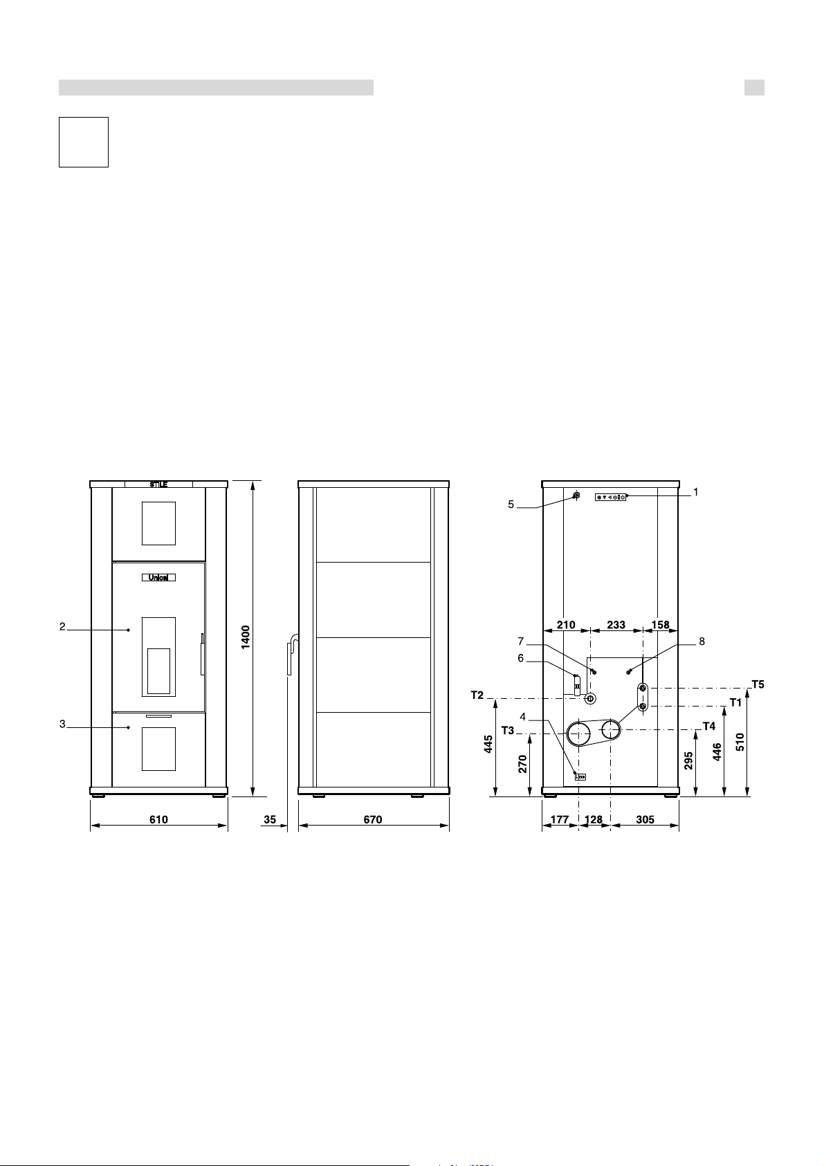
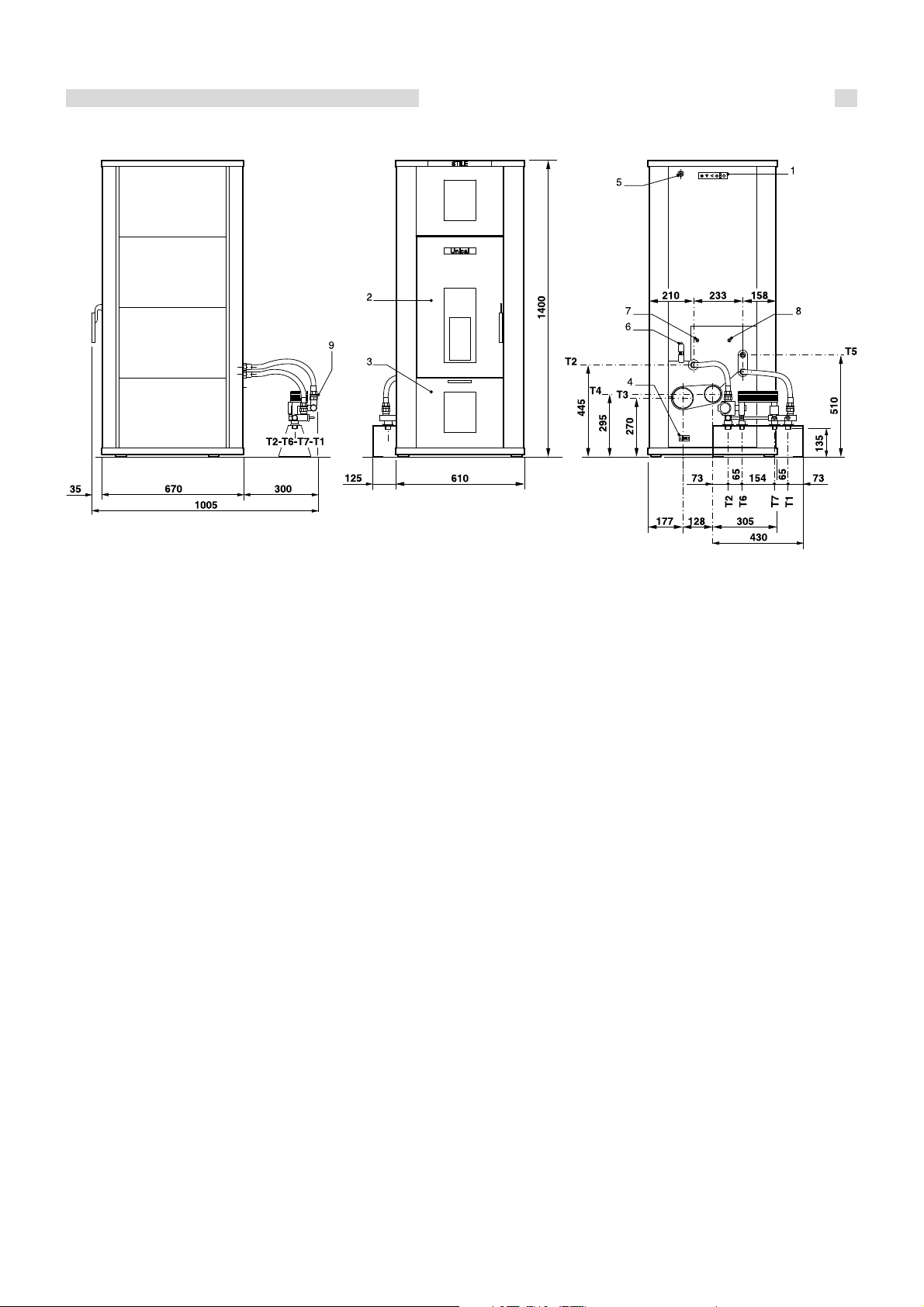
2.2 - HYDRAULIC DIMENSIONS
AND CONNECTIONS
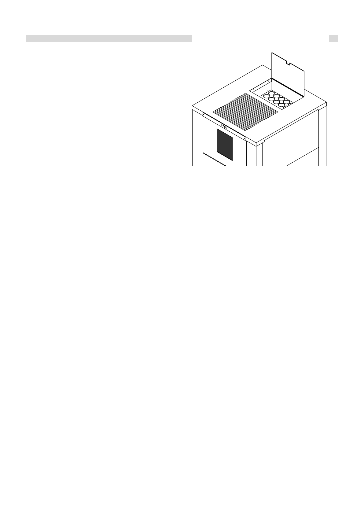
1. Emergency console *
2. Front cleaning door equipped with ceramic glass
3. Bottom cleaning cover
4. Main switch with plug
5. Remote control reception antenna
6. Room thermostat electric connection
7. Manually reset water safety thermostat
8. Manually reset pellet safety thermostat
T1. CH flow (R 3/4)
T2 CH return (R 1)
T3 Chimney connection (ø100)
T4 Air intake connection (ø80)
T5 Safety valve discharge connection (R 3/4)
* Only switches ON/OFF and performs OUTPUT CHANGE, aside from an LED which signals a generic error.
fig. 1
7

Technical features and dimensions
Indicative hydraulic diagram
M Heating system flow
R Heating system return
1 Heating system overpressure valve (2.5 bar) (supplied)
2 Automatic release valve (supplied)
3 Heating system expansion vessel (preloaded at 1 bar) (supplied)
4 System filling tap (not supplied)
5 System shut-off valves (not supplied)
6 Main pump (supplied)
7 System drain tap (not supplied)
Attention!
The diagram above is indicative and can be customised.
For special requirements, please contact our After-Sales Service.
When installing, check the correct direction of the water flow.
fig. 2
8
Technical features and dimensions
Hydraulic dimensions and connections with DOMESTIC HOT WATER PRODUCTION KIT
1. Emergency console *
2. Front cleaning door equipped with ceramic glass
3. Bottom cleaning cover
4. Main switch with plug
5. Remote control reception antenna
6. Room thermostat electric connection
7. Manually reset water safety thermostat
8. Manually reset pellet safety thermostat
9. Domestic hot water production unit
T1 CH flow (R 3/4)
T2 CH return (R 3/4)
T3 Chimney connection (ø100)
T4 Air intake connection (ø80)
T5 Safety valve discharge connection (R 3/4)
T6 Domestic hot water outlet connection
T7. Domestic cold water inlet connection
fig. 3
* Only switches ON/OFF and performs OUTPUT CHANGE, aside from an LED which signals a generic error.
Note: the support bracket of the domestic hot water production unit can be fastened to the ground with plugs.
The maximum clearance of the domestic hot water production unit from the back of the boiler is indicative as it depends on the
length of the flexible hoses.
9

Technical features and dimensions
Indicative hydraulic diagram
M Heating system flow
F Domestic cold water inlet
C Domestic hot water outlet
R Heating system return
1 Heating system overpressure valve (2.5 bar) (supplied)
2 Automatic release valve (supplied)
3 Heating system expansion vessel (preloaded at 1 bar) (supplied)
4 System filling tap (not supplied)
5 System shut-off valves (not supplied)
6 Main pump (supplied)
7 DHW system shut-off valve (not supplied)
8 Domestic cold water inlet filter (not supplied)
9 Differential flow switch (supplied)
10 Plate heat exchanger (supplied)
11 Diverter valve (supplied)
12 Water hammer prevention system (not supplied)
13 System drain tap (not supplied)
Attention!
The diagram above is indicative and can be customised.
For special requirements, please contact our After-Sales Service.
When installing, check the correct direction of the water flow.
fig. 4
10
Technical features and dimensions
2.3 - TECHNICAL DATA
OVERALL OUTPUT
NOMINAL OUTPUT
THERMOCHEMICAL OUTPUT
ELECTRIC ABSORPTION
MAX. WORKING PRESSURE
PELLET TANK CAPACITY
FLUE GAS TEMPERATURE
FLUE GAS MASS FLOW RATE
MINIMUM DRAUGHT
CO VALUE 13%
TOTAL EFFICIENCY
PELLET CONSUMPTION
AUTONOMY
HEAT STOVE CAPACITY
WATER SIDE PRESSURE DROPSA (standard version)*
MAX HEATABLE VOLUME**
DHW PRODUCTION (see note)***
* Pressure drops for flow rate corresponding to a thermal drop of 15K.
** Values calculated based on the Law 10/91 for residential homes with a heat requirement of 30 kcal/hm³. The data is indicative.
*** NOTE: DHW production is subordinated to operation of the system pump. This cannot start up until the water temperature in the heat stove reaches 40°C. Beyond
this threshold it is necessary to consider the time required for the water temperature in the heat stove to reach a degree which allows thermal exchange through
the plate heat exchanger. A pressure drop caused by the thermal exchange is also considered. Therefore, with the heat stove at full capacity and water
temperature of 80°C, with a continuous withdrawal of 10 litres a minute, the outlet temperature from the DHW exchanger will be approximately 40°C with cold water
inlet at approximately 10°C.
The results in the table have been obtained using certified pellets based on the standards DIN 51731, DINplus and ÖNORM M 7135.
(kW) 6,8÷22
(kW) 5,2÷20
(kW)
starting
(W)
full capacity(W)
(bar)
(kg)
(°C)
(g/s)
(Pa)
(%)
(%)
min.
max.
(kg/h)
min.
max.
(h)
at nominal flow rate
at minimum
(l)
(m.w.c.)
(m³)
(l/min.)
8÷27
395
250
2
60
max. 180°C - min. 80°C
10,20
10
< 0,04
81,48
85
1,65
5,62
10,7
36,4
35
0,3
573
10
Emissions: according to UNI EN 14785
Efficiency: according to UNI EN 14785
2.4 - SUPPLY
Controlled combustion system with flue gas
temperature recovery
Flue gas draught control pressure switch
Dual combustion system
Ceramic glass
Two-way remote control
Automatic re-ignition in case of blackout (within 60 seconds)
5-speed forced ventilation
Possibility of setting heat outputs (5 levels)
Weekly programming
standard
standard
standard
standard
standard
standard
standard
standard
standard
11

Technical features and dimensions
2.5 - MAIN COMPONENTS
1. Removable top with pellet loading cover
2. Panel board
3. Front door with ceramic glass
4. Pellet combustion crucible
5. Pellet igniter
6. Upper ash cleaning pan
7. Lower ash cleaning pan
8. Heat exchange pipe scraper system
9. Pellet tank
10. Pellet feeding screw
11. Feeding screw motor
12. System pump
13. Combustion flue gas intake/exhaust unit
M C.H. flow
R C.H. return
A Combustion air intake
F Combustion flue gas exhaust
N.B.: The smoke side of the thermal exchange pipes becomes dirty; it is therefore
advised, every time you load pellets, to activate the scraper system (pos. 8) in the
opposite vertical direction for a few seconds to keep them clear.
2.6 - GENERAL INFORMATION
The main feature of the STILE 27 heat stove is that of burning
natural fuel (pellets) obtained in an environmentally-friendly
way from wood industry waste (sawdust, powders). The
sawdust and powders coming from wood processing, after
having been appropriately cleaned and dried, are compacted
at high pressure giving way to pure wood cylinders: the pellet.
Each cylinder can have variable length and thickness,
respectively, between 1÷3 cm long and 6÷8 mm in diameter.
The main features of the pellet are its low moisture content
(lower than 12%), its high density (about 600 kg/m3) as well
as its regularity and compactness providing this type of fuel a
Net Calorific Value (NCV) of 4100÷5000 kcal/kg.
In order to provide STILE 27 with a long lifespan, Unical advises
using good quality pellets.
The pellets used to feed the heating stove must have high
quality features such as, for example, those determined by
standards DIN 51731 and ÖNORM M 7135. The following a
some of their fundamental data.
fig. 5
12

Technical features and dimensions
Quality standards for Unit of measurement ÖNORM M 7135 DIN 51731 DIN plus
wood Pellet
Diameter mm from 4 to 10 from 4 to 10 from 4 to 10
Length mm 5 x D
Density Kg/dm
3
1
< 50 5 x D
> 1,12 1,0 – 1,4 >1,12
1
Humidity % < 10 < 12 < 10
Ash % < 0,50 < 1,50 < 0,50
Calorific value kWh/kg > 5 4.86 – 5.42 > 5
Sulphur % < 0,04 < 0,08 < 0,04
Nitrogen % < 0,3 < 0,3 < 0,3
Chlorine % < 0,02 < 0,03 < 0,02
Dusts % weight < 2,3 - < 2,3
Bonding agents % of pressed mass < 2
1
No more than 20% of the pellets can be 7.5 times longer than the diameter D.
2
DIN prohibits use of any added substance. However this prohibition is not valid for small heating systems.
2
< 2
The standard DINplus proposes the combination of quality parameters proposed by the standard DIN 51731 and by the
Austrian standard ÖNorm M 7135.
The pellet, as foreseen by current Italian
legislation governing commodity features of
fuels (DPCM 2.10.1995), must be produced
exclusively with untreated wood sawdust
without other materials added.
It is absolutely forbidden to use any solid or
liquid fuel other than pellets to feed STILE
27.
For best operation of STILE 27, it is
recommended to use pellets the quality of which
is certified by an authorised body. The use of poor
quality pellets can cause STILE 27
malfunctioning and shall terminate the warranty.
Storage and handling of pellets are important operations to
be performed with care:
- The fuel must be stored in a dry place which is not cold;
- Pellets must be moved in such a way to avoid breaking
them up into small powder.
Compliance with these two simple rules provides better
combustion efficiency and conserves the moving mechanical
parts of the appliance.
If STILE 27 remains unlit for long periods
(more than seven days), the tank must be
emptied from residual fuel to keep it from
becoming excessively moist which could
cause the appliance to malfunction.
A high moisture content in the pellet can cause
it to break up into powder generating greater
accumulation of residue in the brazier and
blocking the fuel feed system (screw).
13

Installation instructions
3
INSTALLATION
INSTRUCTIONS
3.1 - GENERAL WARNINGS
ATTENTION!
This heat stove is intended solely for the
use for which it was expressly designed.
Any other use is to be considered improper
and therefore dangerous.
This heat stove heats water to a
temperature lower than the atmospheric
pressure boiling temperature.
ATTENTION!
The appliances are designed to be installed
inside suitable rooms or technical spaces
only. The appliances cannot be installed or
operate outdoors. Outdoor installation can
cause malfunctioning and be dangerous.
Choose specifically designed appliances for
outdoor installation.
Before connecting the heat stove, have
professionally qualified personnel:
a) Thoroughly wash all the piping of the system
to remove any residue or impurities which
could jeopardise proper operation of the
heat stove;
b) Check that the chimney/flue has an
appropriate draught, without any
bottlenecks, and that no exhausts from other
appliances are inserted, unless the flue has
been implemented to accommodate several
utilities according to specific standards and
prescriptions in force. Only after this check
can the fitting between the heat stove and
chimney/flue be mounted;
ATTENTION!
The appliance must be installed by a
qualified technician with the technicalprofessional requirements according to law
46/90 who, under his own responsibility,
guarantees compliance with standards
according to good practice rules.
The heat stove must be connected to a central
heating system and/or domestic hot water
production network compatible with its efficiency
and output.
14

3.2 - INSTALLATION STANDARDS
STILE 27 is a heat stove designed to operate with wood
pellets.
It must be installed according to the following standards:
Standard UNI 10683 of 09/2005
Wood or other solid biofuel fed systems.
Installation requirements.
FIELD OF APPLICATION: wood or other solid biofuel fed
systems with a thermochemical input less than 35 kW.
Standard UNI 11263 of 11/2007
Solid biofuels - Characterization of pellet for energy purposes.
Standard UNI 11264 of 11/2007
Solid biofuels - Characterization of wood logs, briquettes and
chips.
LAW March 5,1990 N° 46 and relative applicative regulation
D.P.R. 447 December 6, 1991 (and subsequent amendments).
Safety standards for systems
FIELD OF APPLICATION: without thermal potential limits.
Installation instructions
Standard UNI 10847 of March 2000.
Single flue systems for generators fed by solid and liquid fuels.
Maintenance and control. Guidelines and procedures.
FIELD OF APPLICATION: systems fed with solid and liquid
fuels.
LAW January 9,1991 N°10 and relative applicative regulation
D.P.R. 412 26/08/93 (and subsequent amendments), D.P.R.
n°551 of 21.12.1999.
Regulation with amendments to Italian Presidential Decree.
n° 412 concerning design, installation, operation and
maintenance of thermal systems in buildings, in order to reduce
energy consumption.
FIELD OF APPLICATION: without thermal potential limits.
Law n°186 of 01.03.1968
Installation standard IEC 64-8 / II ed.
Electric systems using rated voltage no greater than 1000 V
AC and 1500 V DC.
Installation standard IEC 64-8 / I ed.
Electric systems in buildings intended for residential and
similar use.
This appliance must be installed according to that
indicated by the standards in force in the country where
the heat stove is installed.
15
Installation instructions
3.3 - PACKAGING
The STILE 27 heat stove is delivered encased on a pallet
and protected by cardboard packaging.
After having removed packaging, make sure that
the supply is complete and undamaged.
If in doubt, do not use the appliance and contact
the supplier.
To handle the heat stove and to remove the pallet
below, remove the top and, using appropriate
lifting systems, fasten the upper hook intended
for this purpose.
Keep the packaging material (cardboard boxes,
straps, plastic bags, etc.) out of the reach of
children as they are potential sources of
danger.
3.4 - INSTALLATION
STILE 27 is a heat generator which withdraws the combustion
air required for the combustion process directly from the
environment in which it is installed.
For this reason, and above all for the safety of the persons
using STILE 27, it must be installed in a sufficiently ventilated
area so that a continuous flow of combustion air is guaranteed.
It is therefore essential to make air vents linked with the outside
which, in compliance with that indicated by Standard UNI
10683, have the following features:
1. Have a free cross-section no less than 80 cm2;
2. Be made close to the floor;
3. Be appropriately protected by metallic mesh or grille so
that the minimum air passage cross-section is not reduced;
4. Be positioned in such a way that it cannot be obstructed.
The correct air influx can also be guaranteed
by using openings towards an adjacent
room as long as that room is provided with
direct ventilation and it has no fire risks such
as depots, garages or storerooms as
regulated by standard UNI 10683.
STILE 27 should be installed in rooms without appliances
which do not operate in an airtight fashion respect to the room
or appliances which can create a vacuum in the room respect
to the outside environment and therefore hinder the draught
of the flue gas exhaust system (UNI 10683).
To make it easier to clean, there must be a clearance space in
front of the heat stove no less than the length of the stove itself.
You must at least make sure that the door can open 90°
unobstructed
Unical will not be held liable for damage to persons, animals
or objects due to failure to comply with the above instruction.
The document envelope, inserted in the combustion chamber,
contains:
- Heating system booklet
- The installation, maintenance and operating instruction
booklet
- Warranty
- Local ventilation requirements adhesive label
If the heat stove is stored for long periods, it should be
adequately protected.
The heat stove can be placed directly on the floor as it is
equipped with a self-supporting frame.
When inspecting compatibility of the heating system, you
should make sure that the support surface (floor) has a support
capacity (kg) suitable to bear the weight of the product. If it is
not adequate, suitable safety measures should be taken (e.g.
load distribution plate).
Furthermore, should the floor be made of combustible material
(such as parquet) it should be protected by using a sheet of
fireproof material underneath STILE 27 sufficiently wider than
the base.
When installation has been performed, the heat stove must
be horizontal and stable, in order to reduce vibrations and
noise.
However clearance space must be left behind the heat stove
and on both sides to allow the casing to be opened to service
the fan and the pellet feeding screw.
During installation, place the outermost
clearance point of STILE 27 at least 80 cm
from combustible and/or flammable
material. If this distance cannot be
maintained, a thermal protection should be
arranged (UNI 7129, UNI 10683).
Do not approach or touch the outer surfaces
of the combustion chamber with flammable
material as it can reach high temperatures
following continuous use.
16
Installation instructions
3.5 - FLUECONNECTION
To connect the flue gas exhaust pipe, local and national
standards must be respected (see Standards UNI 7129 and
UNI 10683).
The chimney is of the utmost importance for correct heat stove
operation: it is therefore necessary that the chimney be
waterproof and properly insulated.
Old or new chimneys, built without respecting the specific
requirements, can be recovered by “piping” the chimney itself.
It will be necessary to introduce a metallic pipe inside the
existing chimney and insulate the space between the metallic
pipe and the chimney.
Chimneys made of prefabricated blocks must have perfectly
sealed joints to avoid that flue condensate smudge the walls
due to permeation.
The entrance to the chimney should be at a 45° angle.
At the base of the chimney a flue inspection opening has to be
made.
It is recommended to insulate the pipe connecting to the
chimney to reduce heat loss and noise.
The dimensions of the chimney must guarantee the necessary
draught required to properly operate the heat stove.
An insufficient draught, besides causing smoke leakage,
considerably reduces the heat output. On the contrary, an
excessive draught causes an abnormal heat output increase,
a higher flue gas temperature in the chimney and too much
fuel consumption.
- The flue gas exhaust must be equipped with inspection
plugs;
- The minimum height of the pipe connected directly to the
flue gas exhaust of STILE 27 is between 2÷3 m;
- If a horizontal section is inevitable, it is recommended that
it be no longer than 1.5 m at most and sloping 3÷5% to
favour the escape of the flue gas;
- Use of a weatherproof terminal to avoid altering the
slight state of overpressure found in the flue (do not fit a
horizontal section at the end of the pipe);
- The exhaust ducts must be made with material resistant to
combustion products and condensation (the inspection
plug can drain any condensation which may be formed);
- Pipes must be built in such a way to guarantee maximum
smoke tightness (UNI 10683);
- It is recommended to insulate the exhaust pipe, especially
the outside part exposed to foul weather.
Do not make sections fully horizontal.
There must be no flue gas exhaust hoods installed or
already existing in the room where the heat generator is
installed to avoid creating a vacuum in the environment.
It is prohibited to close the air vents.
It is forbidden to exhaust flue gas through the wall.
Have the flue cleaned at least once a year; we therefore
recommend having both the chimney and the flue gas
fitting thoroughly cleaned.
Use only exhaust pipes suitable for the type
of fuel used.
The supplier will have no contractual or extracontractual liability for damage caused due
to incorrect installation and use and anyway
failure to comply with the instructions
provided by the manufacturer.
It is prohibited to exhaust STILE 27
combustion products in shared smoke
pipes.
The flue must comply with standards in
force.
The flue gas chimney must be made properly
to favour the normal flow of flue gas from
the combustion chamber towards the
outside in the case of a power outage.
Remember that the elimination of excess heat is managed
optimally by the electronic control unit (modulation,
extinction phase etc.).
The following are the main features of the flue gas exhaust
pipe according to that established by standards UNI 7129
and UNI 10683:
Should the flue or piping catch fire,
immediately switch STILE 27 off and
disconnect it from the household electrical
mains.
Weatherproof
terminal
1.5 metres
fig. 6
H > 4 metres
2-3 metres min
Soot container
with
condensation
drain
17
Installation instructions
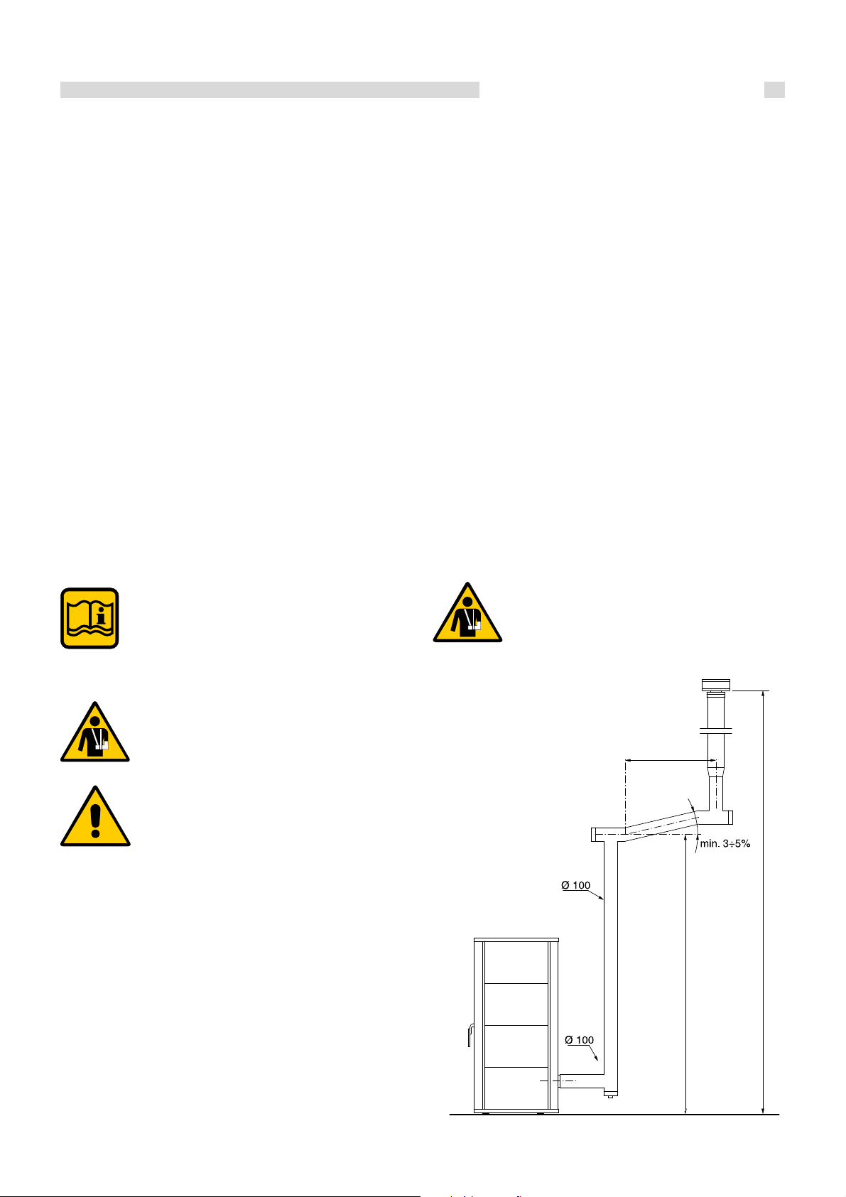
3.5.1 - EXHAUST THROUGH EXTERNAL WALL
Weatherproof
terminal
One of the installation solutions which can be adopted is that
of positioning STILE 27 near a perimeter wall of the home so
that flue gas is discharged directly outside. Here are some
guidelines from the standard UNI 7129 for this particular type
of configuration:
- Always provide an inspection plug which allows you to
perform efficient and periodical cleaning as well as draining
any condensation formed;
- The chimney must be strictly wind and rain proof;
Soot container with
condensation drain
fig. 7
- Appropriately insulate the flue gas exhaust pipe in the
section passing through the wall.
The flue gas exhaust pipe, if completely outside, should be
made in double wall stainless steel to guarantee both greater
resistance to atmospheric agents and a sufficient flue gas
temperature.
18

Installation instructions
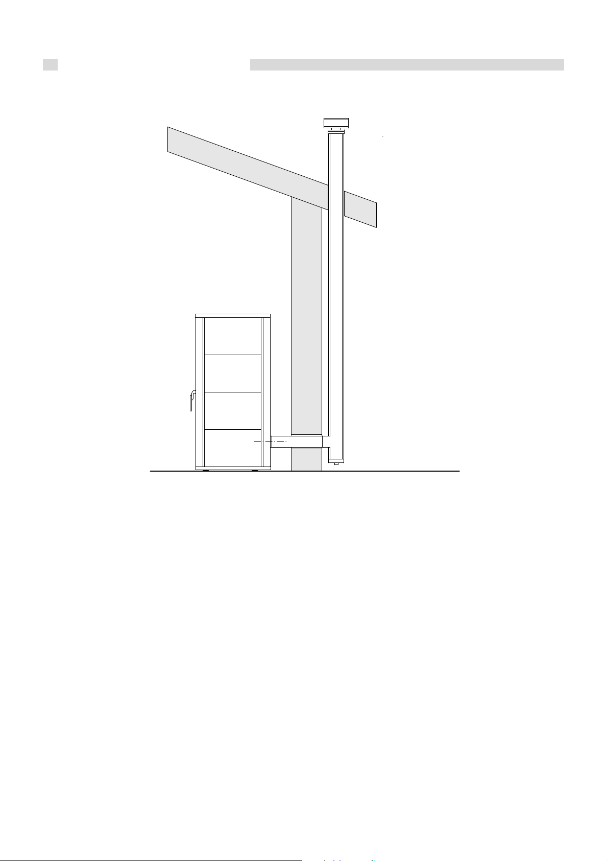
3.5.2 - EXHAUST THROUGH ROOF BY MEANS OF TRADITIONAL FLUE
The pellet combustion flue gas can also be discharged using
a traditional pre-existing flue as long it is made up to standard
(see UNI 10683).
We will briefly list some of the main features highlighted by
the standard which characterise a good chimney:
- Adequate insulation especially in the outside section
exposed to the atmosphere;
- Constant internal cross-section (there must be no crosssection constrictions);
- Made with material resistant to high temperatures, to the
action of combustion products and to the corrosive action
of condensation which could be formed;
- Predominately vertical with deviations no greater than 45°;
Inspectionable soot
container with possible
condensation drain
It is recommended to provide a solid material and/or
condensation collection chamber which can be inspected
through an airtight door.
It is recommended to abide by that established by standards
UNI 9615 and 9731 for the dimensioning of the chimney crosssection and anyhow not to make pipes with a diameter less
than 100 mm.
If there are larger cross-sections, a steel pipe must be inserted
inside the masonry duct.
The steel pipe must be sufficiently insulated
with high temperature resistant material and
sealed from the outer chimney.
fig. 8
19

Installation instructions
3.6 - CONNECTING HEAT STOVE
TO SYSTEM
Attention!
Make sure that there are no mechanical
tension points while connecting the pipes to
avoid the risk of leakage!
Heating flow and return pipes must be connected to the heat
stove at the respective fittings as indicated on page 8.
For the STILE 27 heat stove equipped with the domestic hot
water production kit, see the diagram on page 10.
For the dimensioning of the heating circuit pipes, you must
take into account pressure drops caused by radiators,
3.7 - FILLING THE SYSTEM
Attention!
Do not mix the heating water with incorrect
concentrations of antifreeze or anticorrosion substances! This could damage
the gaskets and cause noise during
operation.
Unical will not be held liable for damage to
persons, animals or objects due to failure
to comply with the instruction above.
After completion of all the hydraulic connections, fill the
heat stove and proceed with the inspection of soundness
of all the connections.
This operation must be performed carefully, respecting the
following phases:
- open the radiator air release valves;
- open the filling tap gradually, making sure that the
automatic air release valves installed on the system work
properly;
- close the radiator air release valves as soon as water
comes out;
- by means of the pressure gauge inserted on the system,
check that pressure reaches approximately 1 bar;
- close the filling tap of the system and bleed air once again
through the radiator air release valves;
-make sure that all the connections are watertight;
-after commissioning the heat stove and bringing
the system to the operating temperature, stop the
pumps and repeat the air bleed operations;
-let the system cool off and, if necessary, return
the water pressure to 1 bar.
NOTE
In systems equipped with closed expansion
vessel, the water pressure in the heating system
- with the system cold - must not drop below 1
bar; open the filling tap when pressure is too low.
This operation must be performed with the system
cool.
thermostatic valves, radiator stopping valves and by the
configuration of the system.
The laying of the pipes must be designed taking every
necessary precaution to avoid air pockets and to facilitate
continuous degassing of the system.
Make sure that the pipes of the water and
heating system are not used as earthing
electrodes of the electric or telephone system.
They are absolutely not suitable for this type of
use. Serious damage could result for the piping,
heat stove and radiators in a short amount of
time.
The pressure gauge fitted on the system allows
you to read circuit pressure.
NOTE
If the system was without electric power, after a
certain idle period, the pump/s could be blocked.
Before turning on the main switch, the pump must
be unblocked by operating as follows:
Introduce a screwdriver in the hole below the
protective screw in the centre of the pump
intended for this purpose and turn the pump shaft
clockwise.
After having unblocked the pump, tighten the
protective screw and make sure there is no water
leakage.
fig. 9
ATTENTION!
After removing the protective screw, a small
amount of water could leak out. Dry off all wet
surfaces before powering the boiler.
20
4
Installation instructions
ELECTRIC
CONNECTIONS
General warnings
The electrical safety of the system is guaranteed only when it
has been properly connected to an efficient earthing system
carried out as intended by safety standards in force: pipes of
the gas, water and heating systems are absolutely unsuitable
as earthing electrodes.
It is necessary to verify this fundamental safety requirement. If
in doubt, have the electric system carefully checked by
professionally qualified personnel as the manufacturer of the
heat stove is not liable for damage caused by failure to provide
an earthing system.
Have professionally qualified personnel check that the electric
system is adequate for the maximum power absorbed by the
system. Make sure in particular that the cross-section of the
cables is suitable for the power absorbed by the loads.
Adapters, multiple sockets and/or extension cords cannot be
used to power the pumps or other loads from the electric mains.
Use of any type of component using electric energy requires
the observance of some fundamental rules, such as:
• do not touch the appliance with wet and/or moist parts of
the body and/or in bare feet;
• do not pull the electric cables;
• do not leave the appliance exposed to atmospheric agents
(rain, sun, etc.) unless expressly designed;
• do not allow children or unskilled persons to use the
appliance.
Remember that a bipolar switch must be
installed on the heat stove power line with over
3 mm between contacts, easy to access, making
maintenance quick and safe.
The power cable must be replaced by authorised technical
personnel. Failure to comply with the above can jeopardise
the safety of the appliance.
230V electric power supply connection
The general electrical connections are illustrated on page 22
and 23.
Installation of the electrical accessories of the heat stove
requires connection to a 230 V - 50 Hz electric mains: This
connection must performed up to standard as intended by
current IEC regulations.
Danger!
Only a qualified technician may perform the
electrical installation.
Before performing connections or any type
of operation on electrical parts, always
disconnect electrical power and make sure
that it cannot be reconnected accidentally.
21

Installation instructions
CRONO
RELE
AUX
FUS
CN8
TRASFORMATORE
SERIALE
CN13
DISPLAY
FUM
CN2
COD. I023_3
CN5
CN1
PE
CN14
N FSCA
COCACCAL1 AL2NV2/PO
CN4
CN6
CN7
CN9
CN15
CN11
JTAG
ENC +5V GND
BLU N.PEL N.H2O N.AMB TERM -TC1+
BUZZER
Terra
Rete 230V 50Hz
M
M
Ventilatore
Fumi
Encoder
ventilatore fumi
ALC = Depressimetro
ALP = Termostato sicurezza vano pellet
ALM = Termostato sicurezza acqua
Candeletta
Coclea
Spina
Wieland
Sonda
acqua
Sonda
fumi
ALC
ALP
blu
blu
blu
grigio
grigio
blu
marrone
marrone
azzurro
rosso
bianco
Ter most.
ambiente
verde
marrone
FILTRO
DI RETE
230V
* posizionata sul posteriore della caldaia
T.A.
(esterno)
*
PI
ALM
Trasduttore
di pressione
OUT giallo
- marrone
+ verde
PRACTICAL WIRING DIAGRAM
Earth
MAINS
FILTER
TRANSFORMER
RELAY
Grey
blue
blue
brown
light blue
brown
blue
230V 50Hz mains
Flue gas
fan
brown
green
Pressure
transducer
Yellow
SERIAL
White
brown
green
Flue gas fan
encoder
probe
Water
CHRONO
probe
Room
temperature
Red
Blue
Screw
Grey
Igniter
probe
Flue gas
ALC = Depression thermostat
ALP = Pellet compartment safety thermostat
ALM = Water safety thermostat
* positioned at back of boiler
Wieland
Plug
Room
thermostat
(external)
fig. 10
22

Installation instructions
estate
inverno
Spina
Wieland
T.A.
caldaia
T1
Presa
Wieland
Spina
Wieland
giallo/verde
Spina
Wieland
N (azzurro) neutro
L1 (nero) riscaldamento
L2 (marrone) sanitario
T1 (azzurro)
T2 (marrone)
T2
Presa
Wieland
Presa
Wieland
valvola
deviatrice
termostato
ambiente
flussostato
230V ~ 50Hz
alimentazione
E/I
N
Fase (230V~ 50Hz)
I
Relé
12V
E
Flussostato
Trasformatore
12V
C
NA
NC
r
r
Valvola
deviatrice
a 3 vie
azzurro
nero
riscaldamento
marrone
sanitario
Termostato
ambiente *
T1 T2
* NOTA: in caso di montaggio del TERMOSTATO AMBIENTE,
togliere il ponte sulla presa Wieland; vedere figura sopra.
C
NA
PRACTICAL WIRING DIAGRAM (with DHW production kit)
summer
winter
power supply
room
diverter
valve
thermostat
flow switch
Wieland
socket
Wieland
plug
yellow/green
L2 (brown)DHW
N (light blue) Neutral
Phase (230V ~50Hz)
L1 (black) heating
Flow switch
Relay
Transformer
* NOTE: when mounting the ROOM THERMOSTAT, remove the
bridge on the Wieland socket; see figure below.
Wieland
socket
Wieland
plug
boiler
T.A.
black
heating
Wieland
plug
Wieland
socket
T1 (light blue)
3-way
diverter
valve
light blue
T2 (brown)
brown
(DHW)
Room
thermostat
fig. 11
23
Installation instructions
HEAT STOVE
5
START-UP
5.1 - COMMISSIONING
Preliminary checks
Commissioning must be done by
professionally qualified personnel. Unical
will not be held liable for damage to persons,
animals or objects due to failure to comply
with the instruction above.
Before commissioning the heat stove check that:
- the adduction of combustion air and flue gas evacuation
are performed correctly according to that laid down by
standards in force;
- the heat stove is provided with all safety and control devices
prescribed by current standards;
- the power supply of the electrical accessories of the heat
stove is 230V - 50Hz;
- the system is filled with water;
- any system shut-off gate valves are open;
- the external main switch is connected;
- the system safety valve is not blocked and is connected to
the sewer system drainage;
Switching boiler on and off
To switch the heat stove on and off, see chapter 7.1.
Information for user
The user must be instructed concerning the use and operation
of his heating system, in particular:
• Deliver these instructions to the user, as well as other
documents concerning the appliance inserted in the
envelope inside the packaging. The user must keep this
documentation for future consultation.
• Inform the user about the importance of the air vents and
the flue gas exhaust system, highlighting their essential
features and the absolute prohibition of modifying them.
• Inform the user concerning controlling the system’s water
pressure as well as operations to restore it.
• Inform the user concerning correct temperature control,
control units/thermostats and radiators for saving energy.
• Remember that the system must receive regular
maintenance at least once a year and a combustion
analysis must be performed if foreseen by standards in
force.
• Should the appliance be sold or transferred to a new owner
or if you move and leave the appliance, always make sure
that the instruction booklets accompany it in order to be
consulted by the new owner and/or installer.
- there is no water leakage;
- ventilation conditions and minimum distances are
guaranteed to perform maintenance.
5.2 - CHECKS AT
COMMISSIONING
GENERAL CONTROLS
Upon commissioning: check that the C.H. system
is full of water and is properly purged, that the
chimney has a sufficient draught, that the electrical
connections have been made correctly (chap. 4)
and that the system’s service pump is not blocked.
24
Inspections and maintenance
6
INSPECTIONS AND
MAINTENANCE
Inspections and maintenance performed
professionally and according to a regular
schedule as well as the use of original spare
parts are of the utmost importance for faultfree operation of the heat stove and to
guarantee its long life.
Maintenance of the appliance is mandatory
in compliance with Laws in force, at the
frequency laid down by D.P.R 412 of August
26, 1993 and subsequent amendments,
concerning the type of fuel used and the heat
stove output.
Failure to perform Inspections and
Maintenance can entail material and
personal damage.
We therefore recommend stipulating an inspection or
maintenance contract.
Inspections help to determine the actual status of the appliance
and to compare it with the nominal status. This is done through
measuring, controls and observation.
Maintenance is required to eliminate any differences between
the actual status and the nominal status. This is normally done
by cleaning, setting and replacing individual components
subject to wear.
Inspection and maintenance instructions
To assure long-term functioning of your
appliance and to avoid altering its approved
status, only original Unical spare parts must
be used.
Before proceeding with maintenance, always perform the
following operations:
• Disconnect the electric mains switch.
• Isolate the appliance from the electric mains by means of
an isolated device with a contact opening of at least 3 mm
(e.g. safety devices or power switches) and make sure that
it cannot be re-connected accidentally.
• Close any shut-off valves on the heating flow and return
pipes, as well as the cold water inlet valve.
After having completed all maintenance work, always perform
the following operations:
• Open the heating flow and return pipes, as well as the
cold water inlet valve.
• If necessary, restore the heating system pressure.
• Reconnect the appliance to the electric mains and engage
the switch.
• Make sure the appliance is flue gas tight and watertight.
• Vent the heating system and restore pressure if necessary.
Maintenance intervals and their extent are determined by a
specialist based on the status of the appliance ascertained
through inspection.
Inspection and maintenance jobs must be performed in the
order shown on page 26.
25

Inspections and maintenance
Boiler body maintenance
Danger!
Before performing any maintenance, make
sure the heat stove and its components
have cooled down.
Warnings
Never drain water from the system, even partially, unless
absolutely necessary.
Periodically check the proper operation and integrity of the
flue gas exhaust pipe and/or device.
If work or maintenance is performed on the structures near
the flue gas pipes and/or flue gas exhaust devices and their
accessories, switch the appliance off and, when the work is
over, check their efficiency.
Do not clean the heat stove and/or its parts with easily
flammable substances (e.g. petrol, alcohol, etc.).
Do not leave flammable substances in the room where the
heat stove is installed.
Do not clean the boiler room while the heat stove is running.
- Remove the bottom panel with the furnace door open,
pulling it by the top part to release it from the blockage
system.
Extract the two ash pans and empty them. To extract the
pans, turn the front pins until they release from the blockage
system.
- IMPORTANT! STILE 27 is equipped with an internal heat
exchanger unit cleaning system which is controlled by
repeatedly pushing the lever in the inner top part of the
pellet combustion chamber.
This operation must be repeated until it slides without any
resistance.
Cleaning the surface of the heat exchanger pipes
guarantees the most efficient thermal exchange possible.
- It could also be necessary to clean the glass as it inevitably
gets dirty.
The frequency of this cleaning depends on use and the
quality of the pellets.
Clean the glass when it is completely cooled off, using
specific nonabrasive cleansers.
When cleaning is finished, put all pieces back in place
acting in the opposite order.
The frequency with which the glass is cleaned is
linked to how much the heat stove is used.
At the end of each heating period, inspect the heat stove to
keep the system in perfect efficiency.
Thorough maintenance always enhances energy saving and
safety.
IMPORTANT
Use brushes and a vacuum cleaner to clean
the heat stove; if rags are used, make sure they
are all recovered.
CLEANING AND ROUTINE MAINTENANCE STILE 27
STILE 27 must receive regular maintenance to guarantee its
correct and efficient operation.
The following cleaning operations must be performed only
when the heat stove is completely cold and disconnected
from the household electric mains.
Daily
- Remove the ashes from the combustion chamber using a
vacuum cleaner intended for recovery of combustion
products.
- This operation will be easier by removing the crucible from
the combustion chamber, as shown in the following figure.
Check the integrity of the bottom grate of the crucible and
in case of doubt, have it replaced.
Eliminate incrustations which obstruct the air passage
vents.
Remove any slag deposited around the crucible support.
fig. 12
26
LOADING THE PELLET
Access the pellet tank by lifting the top cover.
We recommend using only guaranteed quality pellets: this
will allow STILE 27 to work with high efficiency, to save on
maintenance and to make your heat stove last longer.
EXTRAORDINARY MAINTENANCE STILE 27
Inspections and maintenance
fig. 13
At the end of each heating season, perform a general cleaning
of the heat stove acting as follows. During summer, keep the
heat stove door closed.
- Clean the combustion chamber using a vacuum cleaner
intended for recovery of combustion products after having
removed the crucible.
- Remove the top cover by pulling it upwards.
- Disassemble the top cover and clean the heat exchanger
pipe unit with a vacuum cleaner.
- Remove the bottom front panel (pulling the top) and empty
the pans.
Vacuum the combustion residue.
- Check the integrity of the glass door sealing gasket and
the air tightness of the combustion chamber.
Replace the gasket if necessary.
- We recommend emptying the pellet tank completely at the
end of the heating season to prevent it from deteriorating
due to moisture, causing possible malfunctioning the next
time it is lit.
- We also recommend thoroughly cleaning both the chimney
and the flue gas fitting to avoid the risk of a fire.
- Put all the components back in place, sealing the required
parts with high temperature resistant silicon.
Every two years, clean the steel impeller of the flue gas intake
fan and its housing.
It can be reached after having pulled off the top and side
panels and having removed the 4 screws.
It can be cleaned conveniently with a vacuum cleaner.
Check the integrity of the pellet feeding system (screw, control
motor, thrust bearing) and have it overhauled if necessary.
Check the correct positioning of the pellet ignition resistance.
Check the preload of the expansion vessel which must be
approximately 1 bar with the system cool.
27

Inspections and maintenance
6.1 - TROUBLESHOOTING
This paragraph provides the purchaser of our product with a quick and efficient guide to understand problems which could
arise while using STILE 27.
Problem found
The remote control display does
not switch on.
The remote control display
indicates NO FIELD.
The fan does not work.
Repeated failed ignitions,
the flame is weak, the crucible
fills up with fuel.
Possible cause
1 Batteries missing / discharged.
2 The remote control is faulty.
1 The heat stove is disconnected from the
electric mains.
Possible temporary power cut.
2 Protective fuse blown.
3 Main switch at rear of heat stove could
be OFF.
1 Possible obstruction of tangential fan
inlets.
2 The fan could be burnt or blocked.
3 Malfunctioning of sensors or circuit
board.
1 Possible obstruction of combustion air
inlet of crucible or its holes.
2 The pellet could be too moist.
3 Electric or electronic problem in board.
4 The ignition resistance or thermal probe
could be faulty.
5 The door could be closed improperly.
6 Improper functioning of combustion air
exhaust system (flue gas fan).
Remedy
1 Insert/replace the batteries.
2 Contact technical assistance.
1 Make sure power is present and that the
power cable is connected.
2 Contact technical assistance.
3 Place the switch at ON.
1 Contact technical assistance.
2 Contact technical assistance.
3 Contact technical assistance.
1 Empty the pellet crucible.
Clean the crucible and make sure the
combustion air passage holes are not
obstructed.
2 Change the type of pellet (see
specifications on page 10).
3 Contact technical assistance.
4 Contact technical assistance.
5 Contact technical assistance to replace
the gaskets.
6 Contact technical assistance.
The pellet does not drop into the
brazier.
Low level of hot water in
radiators.
Heat stove blockage due to fuel
gas overtemperature.
Heat stove blockage due to
water overtemperature.
Faulty control unit watch.
Should these possible solutions fail to resolve the problem you detected, please contact the customer assistance service for
further information.
28
1 Pellet tank empty.
2 The pellet feeding gearmotor is faulty.
3 Faulty electronic control unit.
1 Air in system.
2 Possible pump malfunctioning.
3 Faulty water temperature probe.
4 Faulty electronic control unit.
1 Flue gas exchanger obstructed.
2 Faulty fuel gas temperature probe.
1 Safety thermostat needs to be reset.
2 Safety thermostat faulty.
3 Faulty electronic control unit.
1 Watch buffer battery flat.
1 Fill pellet tank.
2 Contact technical assistance.
3 Contact technical assistance.
1 Bleed the system.
2 Contact technical assistance.
3 Contact technical assistance.
4 Contact technical assistance.
1 Contact technical assistance to clean the
flue gas circuit.
2 Contact technical assistance.
1 Reset the safety thermostat in the rear of
the heat stove.
2 Contact technical assistance.
3 Contact technical assistance.
1 Contact technical assistance.

Programming setting
PROGRAMMING
7
SETTING
7.1 - USING THE PRODUCT
Before describing in detail how to operate the product, we remind you that it is mandatory to respect the relevant national and
local provisions, rules and laws in force.
To better understand how to operate the product, we have provided diagrams accompanied by an in-depth description of the
remote control and the programming modes of the product, as well as operations to be performed to commission STILE 27.
STILE 27 is lit very easily. After having connected it to the household electric mains, press the ON/OFF key only after having
properly connected the product to an adequate water system (see our installation guidelines).
It is strictly forbidden to operate STILE 27 without having properly connected it to an adequate water
system, or else the warranty shall be terminated.
The first few times that the heat stove is lit, there could be vapours and bad smells of the painted parts.
These problems are intrinsic to the chemical stabilising process of the special paint used. Therefore the
room must be well ventilated during this phase.
Remember that the appliance must always operate with the combustion chamber door closed.
Though the surface temperatures which our appliance reaches are not extremely high, we recommend
the utmost attention and caution when touching it. The outer surfaces of the combustion chamber in
particular can become red-hot ensuing intensive use.
Place the outermost clearance point of the heat stove 80 cm from combustible and/or flammable material.
If this distance cannot be maintained, a thermal protection should be arranged (UNI 7129, UNI 10683).
To avoid the onset of malfunctioning which could in turn be a source of damage to persons or objects,
we recommend avoiding switching the appliance on and off suddenly and continuously, but to follow
the timetables foreseen by the manufacturer for these operations.
We also recommend thoroughly cleaning both the chimney and the flue gas fitting (at least once during the
whole season of operation) to avoid the risk of a fire.
The appliance must operate with the ash pan hermetically shut.
We recommend to avoid operating the heat stove with an instable electric power supply; continuous
blackouts could cause malfunctioning.
29

Programming setting
08 : 10
M-2-3-01
PROG-1
START
input livello di menù
dialogo
14 : 24
21°C
SPENTO
orologio temperatura ambiente
dialogo temperatura acqua
45°C
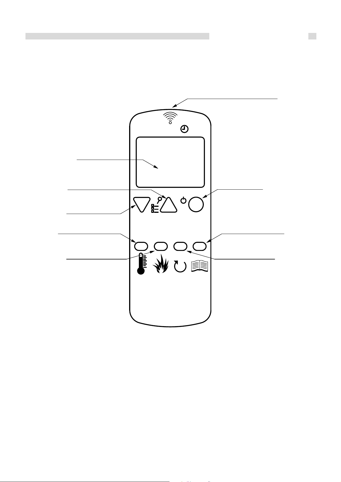
7.2 - REMOTE CONTROL
The remote control displays information concerning the
operating status of STILE 27.
By accessing the menu, you can obtain various types of
displays and perform the settings available depending on the
access level.
Depending on the operating mode, the displays can take on
different meanings according to the position on the screen.
Example with STILE 27 off.
clock
The following figure shows the arrangement of the
messages during programming or operating parameter
setting. In particular:
- The input area displays the entered programming values.
- The menu level area displays the current menu level. See
the menu chapter further on.
room temperature
water temperaturedialogue
fig. 14
input
30
menu level
dialogue
fig. 15
1 2 3
4 5 6 7
DISPLAY
INCREMENTO
DECREMENTO
SET TEMPERATURA
AMBIENTE
Scorri menù
ON / OFF
ESCI DA MENÙ
ACCESSO AL MENÙ/
CONFERMA DATO
SET TEMPERATURA
ACQUA DI CALDAIA
SENSORE TEMPERATURA
AMBIENTE
SET POTENZA
Scorri menù
The figure below, describes the keys of the remote control
and the functions linked to them.
The set operations are viewed on the display.
DISPLAY
INCREASE
Programming setting
SET ROOM
TEMPERATURE
ON/OFF
EXIT MENU
DECREASE
SET ROOM
TEMPERATURE
Scroll menu
SET OUTPUT
Scroll menu
SET BOILER WATER
ACCESS MENU/
CONFIRM DATA
TEMPERATURE
fig. 16
31
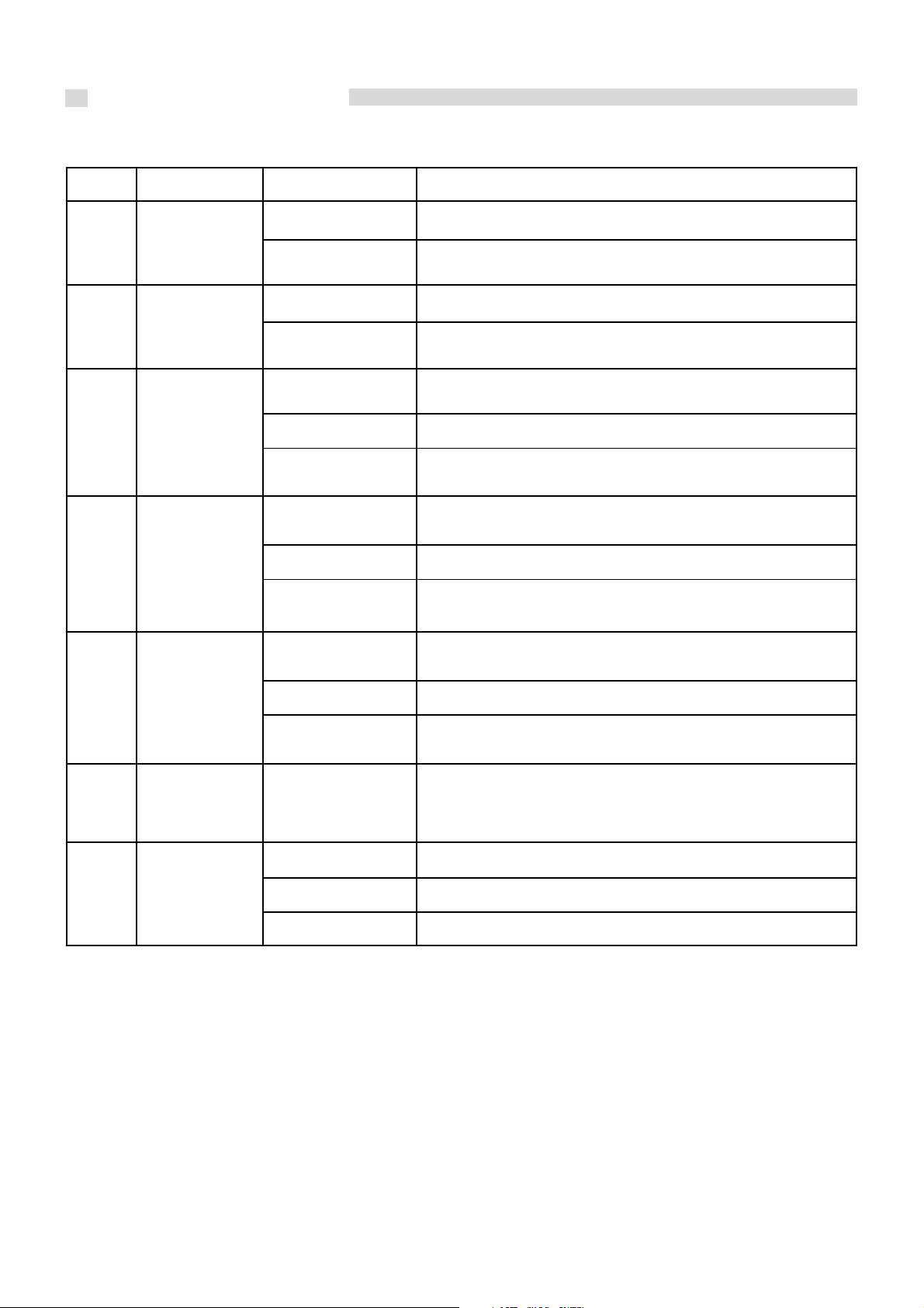
Programming setting
7.3 - FUNCTION OF BUTTONS
button action description mode
1
temperature
(1)
PROGRAMMINGDecrease
with keys 4 / 5 / 6
pressed
2
temperature
(2)
3
ON /OFF
unblock
4
room
temperature
5
output
with keys 4 / 5 / 6
pressed
WORKING
BLOCK Unblocks STILE 27 and switches it off
MENU /
PROGRAMMING
WORKING / OFFSet
MENU Passes to the item of the next menu
PROGRAMMING Returns to the item of the next submenu, modifications performed
WORKING / OFFSet boiler
Modifies / decreases the value of the selected menu
Decreases the room temperature
/ modifies output value / decreases water temperature
Modifies / increases the value of the selected menuPROGRAMMINGIncrease
Increases the room temperature
/ modifies output value / increases water temperature
Pressed for 2 seconds, it switches STILE 27 on or off if it is
off or on respectively
Accesses the higher menu level, modifications performed are
memorised
Modifies the room temperature of STILE 27
(scroll with keys 1 and 2)
are memorised
Modifies output of STILE 27
(scroll with keys 1 and 2)
MENU Passes to the item of the previous menu
PROGRAMMING Passes to the item of the previous submenu, modifications performed
are memorised
6
7
Set
water
temperature
of boiler
Menu
WORKING / OFF
WORKING / OFF
MENU Accesses the next submenu level
PROGRAMMING Sets the value and passes to the item of the next menu
Modifies water temperature of STILE 27
(scroll with keys 1 and 2)
Accesses the MENU
32
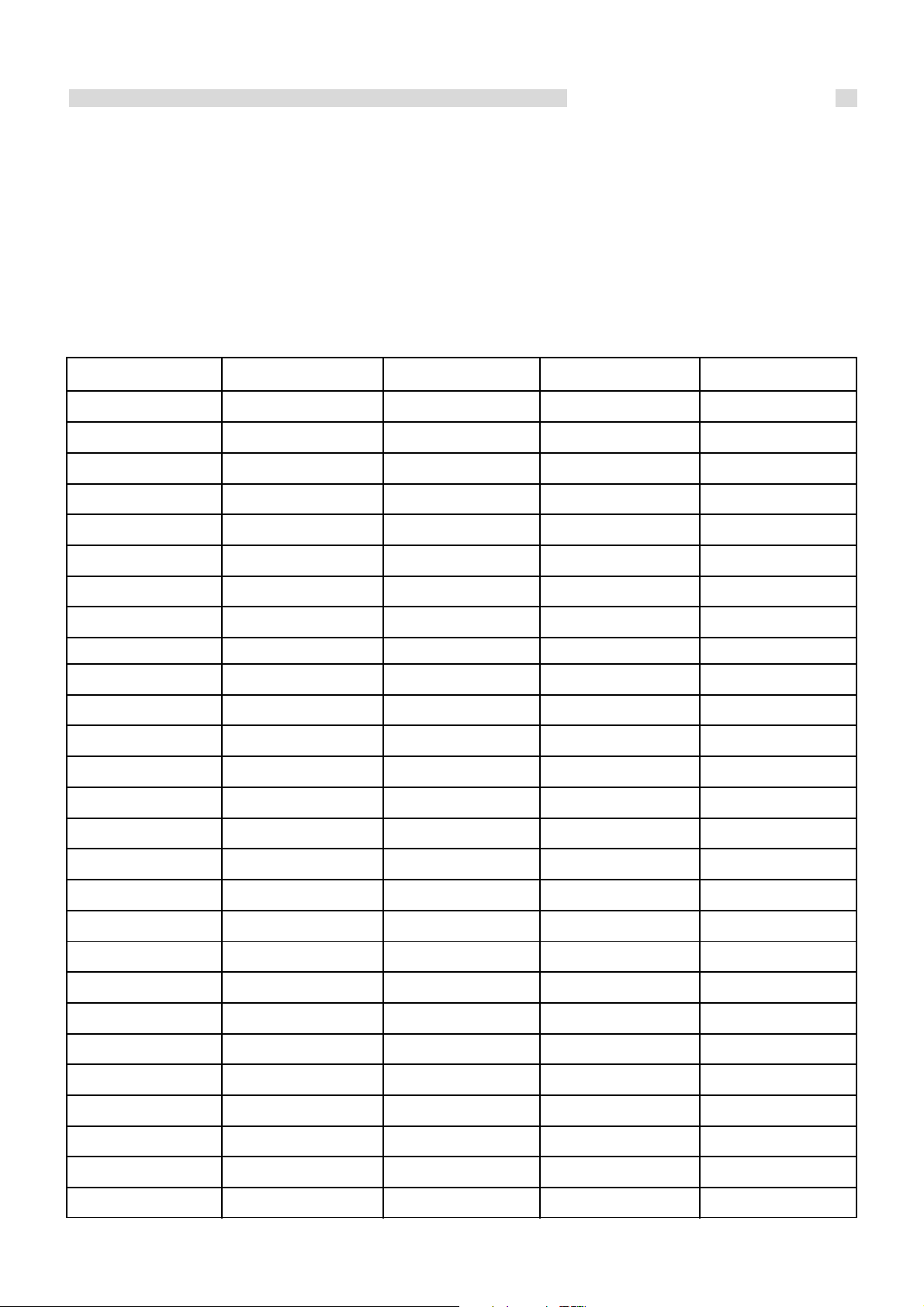
Programming setting
7.4 - MENU
By pressing key 7 (MENU) you access the menu.
This is divided into various items and levels which allow to access board settings and programming.
The items of the menus providing access to technical programming are protected by password.
7.4.1 - USER MENU
The following table synthetically describes the structure of the menu, in this paragraph focusing only on selections available for
the user.
level 1 level 2 level 3 level 4 value
01 - clock setting
day week01 - day
time02 - hours
minute03 - minutes
day month04 - day
02 - chrono setting
month05 - month
year06 - year
01 - enable chrono
01 - enable chrono on / off
02 - program day
01 - chrono day on / off
02 - start 1 day time
03 - stop 1 day time
04 - start 2 day time
05 - stop 2 day time
03 - program week
01 - chrono week on / off
02 - start prog 1 time
03 - stop prog 1 time
04 - Monday prog 1 on / off
05 - Tuesday prog 1 on / off
06 - Wednesday prog 1 on / off
07 - Thursday prog 1 on / off
08 - Friday prog 1 on / off
09 - Saturday prog 1 on / off
10 - Sunday prog 1 on / off
33
Programming setting
level 1 level 2 level 3 level 4 value
11 - start prog 2
12 - stop prog 2
13 - Monday prog 2
14 - Tuesday prog 2
15 - Wednesday prog 2
16 - Thursday prog 2
17 - Friday prog 2
18 - Saturday prog 2
19 - Sunday prog 2
20 - start prog 3
21 - stop prog 3
22 - Monday prog 3
23 - Tuesday prog 3
24 - Wednesday prog 3
25 - Thursday prog 3
26 - Friday prog 3
time
time
on / off
on / off
on / off
on / off
on / off
on / off
on / off
time
time
on / off
on / off
on / off
on / off
on / off
04 - program week-end
27 - Saturday prog 3
28 - Sunday prog 3
29 - start prog 4
30 - stop prog 4
31 - Monday prog 4
32 - Tuesday prog 4
33 - Wednesday prog 4
34 - Thursday prog 4
35 - Friday prog 4
36 - Saturday prog 4
37 - Sunday prog 4
01 - chrono week-end
02 - start 1
03 - stop 1
on / off
on / off
time
time
on / off
on / off
on / off
on / off
on / off
on / off
on / off
34
04 - start 2
05 - stop 2

oFF
M-2-1-01
CRONO
ABILITA
input livello di menù
dialogo
03 - choose language
06
MEnu 02
OROLOGIO
MESE
input livello di menù
dialogo
Programming setting
01 - Italian set
02 - French
03 - English
04 - German
04 - standby mode
05 - buzzer
06 - initial load
07 - heat stove status
7.4.2 - MENU 01 - clock setting
Sets the current time and date.
The board is provided with a lithium
battery which provides the internal clock
with over 3 / 5 years of autonomy.
input
set
set
set
on / off
on / off
set
—
menu level
7.4.3 - MENU 02 - chrono setting
Submenu 02 - 01 - enable chrono
Allows to enable and disable
all the functions of the chronothermostat.
input
dialogue
dialogue
fig. 17
menu level
fig. 18
35

Programming setting
05 : 40
M-2-3-02
PROG - 1
START
input livello di menù
dialogo
08 : 15
M-2-2-02
GIORNO
START 1
input livello di menù
dialogo
Submenu 02 - 02 - daily program
Allows to enable, disable and set the daily chronothermostat
functions.
input
dialogue
It is possible to set two operating time periods delimited by the
times set according to the following table where the OFF
setting tells the clock to ignore the control:
selection meaning possible values
START 1
activation time
menu level
fig. 19
time - OFF
STOP 1
START 2
STOP 2
Submenu 02 - 03 - weekly program
Allows to enable, disable and set the weekly chronothermostat
functions.
deactivation time
activation time
deactivation time
input
time - OFF
time - OFF
time - OFF
menu level
36
dialogue
fig. 20

The weekly programmer has 4 independent programs whose
final effect is composed of the combination of 4 single
programs.
The weekly programmer can be activated or deactivated.
Furthermore, by setting OFF in the time field, the clock ignores
the corresponding command.
Attention: perform programming carefully, in general
keeping from overlapping activation and/or deactivation
times on the same day in different programs.
PROGRAM 1
Programming setting
menu level
02-03-02
02-03-03
02-03-04
02-03-05
PROGRAM 2
menu level
02-03-11
02-03-12
selection meaning possible values
START PROG 1
STOP PROG 1
MONDAY PROG 1
TUESDAY PROG 1
activation time
deactivation time
time - OFF
time - OFF
on / off
on / off
WEDNESDAY PROG 1 on / off02-03-06
THURSDAY PROG 1 on / off02-03-07
FRIDAY PROG 1 on / off02-03-08
SATURDAY PROG 1 on / off02-03-09
SUNDAY PROG 1 on / off02-03-10
selection meaning possible values
START PROG 2
STOP PROG 2
activation time
deactivation time
time - OFF
time - OFF
02-03-13
02-03-14
MONDAY PROG 2
TUESDAY PROG 2
WEDNESDAY PROG 2 on / off02-03-15
THURSDAY PROG 2 on / off02-03-16
FRIDAY PROG 2 on / off02-03-17
SATURDAY PROG 2 on / off02-03-18
SUNDAY PROG 2 on / off02-03-19
on / off
on / off
37

Programming setting
08 : 30
M-2-4-03
WEEK-END
STOP 1
input livello di menù
dialogo
PROGRAM 3
menu level
02-03-20
02-03-21
02-03-22
02-03-23
PROGRAM 4
menu level
02-03-29
02-03-30
selection meaning possible values
START PROG 3
STOP PROG 3
MONDAY PROG 3
TUESDAY PROG 3
WEDNESDAY PROG 3 on / off02-03-24
THURSDAY PROG 3 on / off02-03-25
FRIDAY PROG 3 on / off02-03-26
SATURDAY PROG 3 on / off02-03-27
SUNDAY PROG 3 on / off02-03-28
selection meaning possible values
START PROG 4
STOP PROG 4
activation time
deactivation time
activation time
deactivation time
time - OFF
time - OFF
on / off
on / off
time - OFF
time - OFF
02-03-31
02-03-32
Submenu 02 - 04 - weekend program
Allows to enable, disable and set
chronothermostat functions in the weekend
(days 5 and 6, namely Saturday and Sunday).
MONDAY PROG 4
TUESDAY PROG 4
WEDNESDAY PROG 4 on / off02-03-33
THURSDAY PROG 4 on / off02-03-34
FRIDAY PROG 4 on / off02-03-35
SATURDAY PROG 4 on / off02-03-36
SUNDAY PROG 4 on / off02-03-37
input
on / off
on / off
menu level
38
dialogue
fig. 21
fig. 18
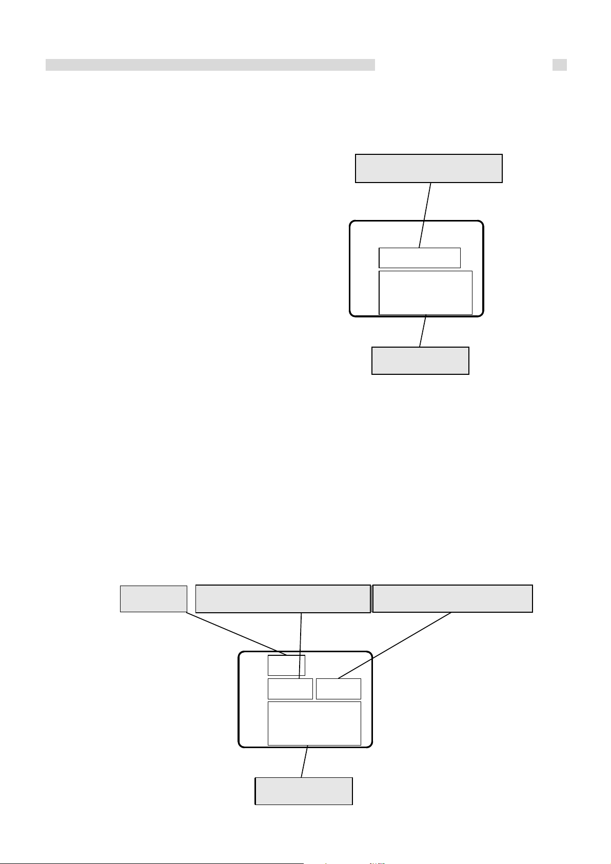
Programming setting
MEnu 01
LINGUA
ITALIANO
livello di menù
dialogo
76”
22°C
INIZIALE
CARICO
timer temperatura acqua
dialogo
22°C
temperatura ambiente
SUGGESTION: in order to avoid confusion and unwanted starting and stopping operations, activate one program at
a time if you do not know exactly what you want to achieve.
Deactivate the daily program if you wish to use the weekly program. Always keep the weekend program deactivated
if you use the weekly program in programs 1, 2, 3 and 4.
Only activate the weekend program after having deactivated the weekly program.
7.4.4 - MENU 03 - choose language
menu level
Allows to select the dialogue language from those available.
fig. 22
dialogue
7.4.5 - MENU 04 - standby mode
Activates “STANDBY” mode which leads the heat stove to
switch off after the water temperature has reached the setpoint beyond the time determined by the triggering of the
external thermostat.
Refer to paragraphs 7.5.8 to 7.5.9 for a detailed description of
the Standby function.
7.4.6 - MENU 05 - buzzer mode
When “OFF”, it disables the acoustic alarm.
7.4.7 - MENU 06 - initial load
Allows to perform a pellet preloading for time of 90” with the
heat stove off and cold. Start with key 1 and stop with key 3.
room temperature
water temperature
dialogue
fig. 23
fig. 20
39
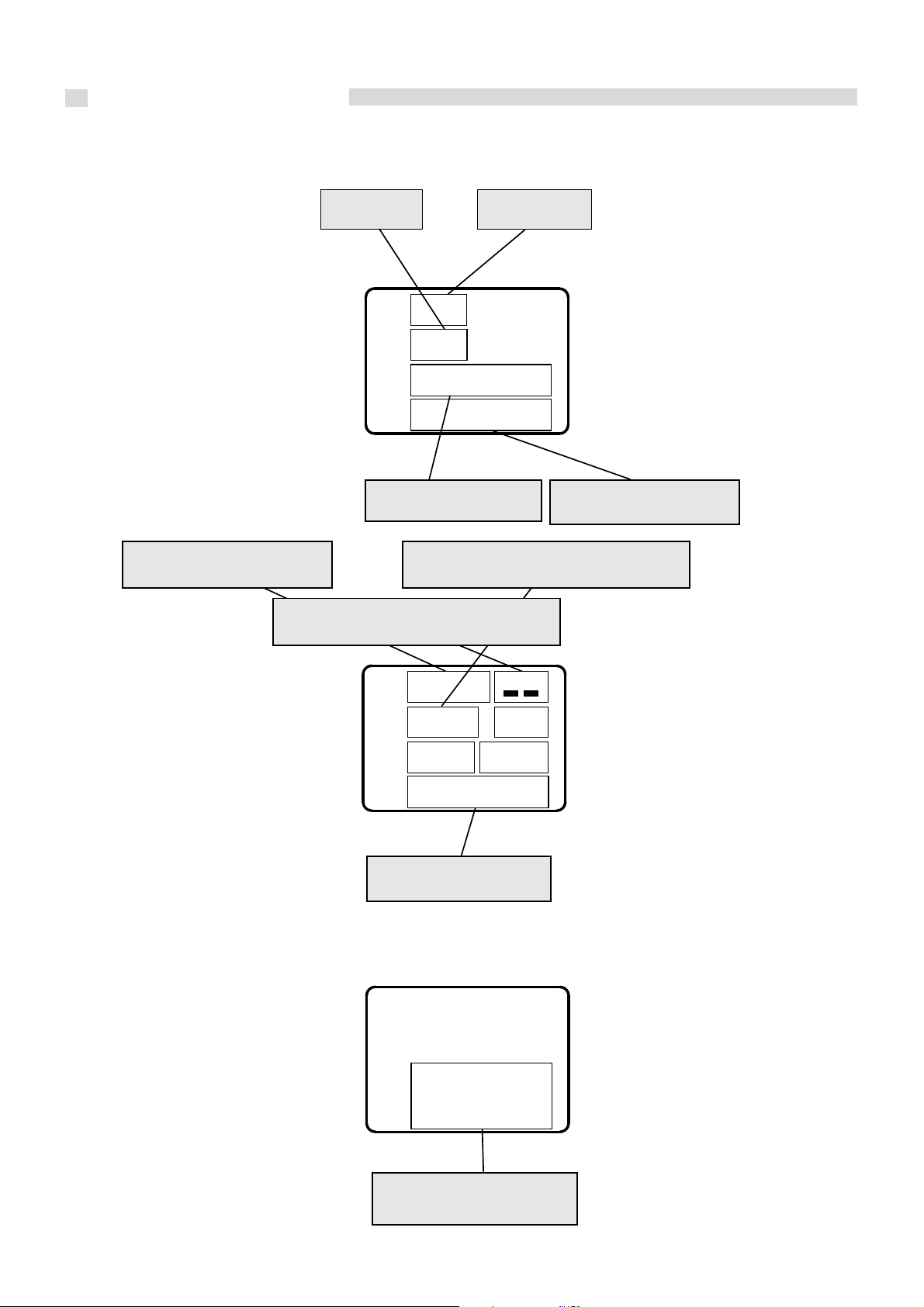
Programming setting
117°C
1100
STATO 4
temperatura fumi
stato operativo
velocità aspiratore fumi
stato scambiatori 2 e 3
10”
82’
60 A2 13 V
230 V
timer 1
bassa tensione
time-out
tensione rete
GUASTO
ASPIRAT-
allarme in corso
7.4.8 - MENU 07 - heat stove status
Displays the instant status of the
heat stove providing the status of
the various devices connected to it.
Various pages are available
displayed one after another.
mains voltage low voltage
flue gas temperature flue gas intake fan speed
exchangers 2 and 3 status
operating status
fig. 24
fig. 25
40
alarm in progress
fig. 26

Programming setting
14 : 24
21°C
SPENTO
orologio temperatura ambiente
dialogo temperatura acqua
49°C
14 : 35
21°C
START
orologio temperatura ambiente
dialogo temperatura acqua
36°C
7.5 - USER OPERATING MODE
The normal operating mode of the panel installed on STILE 27 is described hereafter referring to the functions available for the
user.
The subsequent paragraphs analyse the technical programming mode.
Before starting up STILE 27, the display appears as follows.
clock
dialogue
7.5.1 - LIGHTING STILE 27
To light STILE 27, press 3 for a few seconds.
Ignition is indicated on the display as shown in the following figure
room temperature
water temperature
fig. 27
clock
7.5.2 - STARTING PHASE
STILE 27 carries out the starting phases in sequence according to the modes defined by the parameters which manage their
levels and times.
7.5.3 - FAILED IGNITION
After 20 minutes have elapsed, if the flue gas temperature has not reached the minimum allowed value + 2°C, STILE 27 goes
into the alarm status.
dialogue
room temperature
water temperature
fig. 28
41

Programming setting
15 : 18
21°C
LAVORO
orologio temperatura ambiente
dialogo potenza
P-3
SET TEMP
valore impostato
dialogo
AMBIENTE
28°C
7.5.4 - HEAT STOVE WORKING
When the starting phase has ended successfully, the heat stove switches to working mode which represents the normal operating
mode. If the temperature of the heat stove is greater than 50°C, the system pump switches on.
clock
dialogue
7.5.5 - CHANGING ROOM TEMPERATURE SETTING
To change the room temperature, just select the ROOM SETTING MODIFICATION mode by pressing key 4.
Then press keys 1 and 2. The display shows the current temperature SETTING status.
N.B. The thermostat leaves the factory with the external room thermostat bridged in order to disable the internal room probe
function of the heat stove. This avoids unintentional modulations due to small environments.
If you wish to use the room probe inside the heat stove, remove the bridge on the rear pin marked “room thermostat”.
room temperature
output
fig. 29
7.5.6 - USING EXTERNAL THERMOSTAT / CHRONOTHERMOSTAT
If you wish to use an external room thermostat, perform the connection on the back of the heat stove on the pin marked “room
thermostat” in terminals T1 and T2.
· external thermostat: on STILE 27, set a temperature of 7°C.
· external chronothermostat: on STILE 27, set a temperature of 7°C and disable the chrono functions from the menu 03-01.
set value
dialogue
fig. 30
42
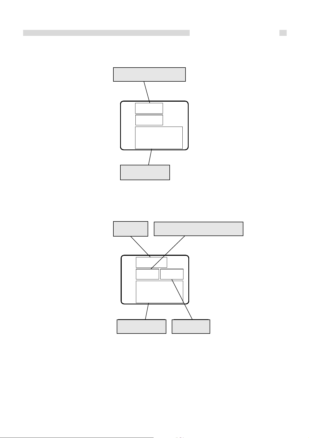
Programming setting
SET TEMP
valore impostato
dialogo
ACQUA
55°C
dialogo
orologio temperatura ambiente
16 : 40
27°C
LAVORO
potenza
P-2
MODULA
7.5.7 - CHANGING WATER TEMPERATURE SETTING
To change the water temperature, just select the WATER SETTING MODIFICATION mode by pressing key 6.
Then press keys 1 and 2. The display shows the current temperature SETTING status.
set value
dialogue
7.5.8 - THE ROOM TEMPERATURE REACHES THE SET TEMPERATURE
(SET temperature)
When the room temperature has reached the set value, the heat output is automatically brought to the minimum value,
MODULATION condition.
N.B. This is only possible if the bridge of the room thermostat behind the heat stove has been removed.
clock
room temperature
fig. 31
If the STANDBY mode has been activated, STILE 27 switches off; namely is placed in STANDBY, with a 5 minute delay and after
having exceeded the value (T
+ 2°C).
SET
dialogue
output
fig. 32
43

Programming setting
dialogo
orologio temperatura ambiente
16 : 40
LAVORO
MODULA
27°C 55°C
temperatura acqua
dialogo
orologio temperatura ambiente
22 : 25
ATTESA
RAFFRED-
24°C 56°C
temperatura acqua
7.5.9 - THE WATER TEMPERATURE REACHES THE SET TEMPERATURE
(SET water temperature)
When the water temperature has reached the set value, even simultaneously to that described in paragraph 7.5.8, the heat
output is automatically brought to the minimum value, MODULATION condition.
clock
dialogue
Similarly to that which occurs for the room temperature, if the STANDBY mode has been activated, STILE 27 switches off;
namely is placed in STANDBY, with a 5 minute delay and after having exceeded the value (T
(only if the Wieland plug of the external TA has a bridge on T1 and T2).
7.5.10 - RESTARTING AFTER EXTINCTION HAVING REACHED SET ROOM AND/OR WATER
TEMPERATURE
After the STANDBY extinction, STILE 27 places itself in cooling condition bringing the flue gas intake fan to a maximum. See
figure 21. The restarting conditions are:
room temperature
water temperature
+ 2°C).
SET
fig. 33
Air:
T
room < (TSET
Water:
T
water < (TSET
- 2°C) and simultaneously Tflue gas < 50°C
- 2°C) and simultaneously Tflue gas < 50°C
clock
dialogue
room temperature
water temperature
fig. 34
44

Programming setting
dialogo
orologio temperatura ambiente
16 : 40
22°C
PULIZIA
potenza
P-2
BRACIERE
dialogo
orologio temperatura ambiente
21 : 10
23°C
PULIZIA
potenza
P-3
FINALE
7.5.11 - CLEANING BRAZIER
During normal operation in working mode, at set intervals the “BRAZIER CLEANING” mode is activated.
clock
dialogue
7.5.12 - HEAT STOVE EXTINCTION
To switch STILE 27 off, just press button 3 for about 2 seconds.
The feed screw stops immediately and the flue gas extractor switches to high speed.
The FINAL CLEANING phase is performed.
The flue gas extractor is disabled after the flue gas temperature has dropped below 50°C.
room temperature
output
fig. 35
clock
dialogue
room temperature
output
fig. 36
45

Programming setting
dialogo
orologio temperatura ambiente
21 : 10
22°C
SPENTO
potenza
P-1
dialogo
orologio temperatura ambiente
21 : 25
21°C
ATTESA
potenza
P-1
RAFFRED-
7.5.13 - HEAT STOVE OFF
clock
dialogue
7.5.14 - RE-IGNITION OF THE HEAT STOVE
It will not be possible to restart the heat stove until the flue gas temperature has dropped below 50°C and 5 minutes have
passed.
clock
room temperature
output
room temperature
fig. 37
46
dialogue
output
fig. 38

7.6 - WHAT HAPPENS IF ...
12 : 42
MANCATA
ACCENS-
22°C
12 : 42
PULIZIA
FINALE
22°C
7.6.1 - THE PELLET DOES NOT LIGHT
In case of failed ignition, the alarm message NO ACC appears.
Programming setting
Press key 3 to restore STILE 27 to standard conditions.
7.6.2 - ELECTRIC POWER IS MISSING
If the mains voltage is missing for over 60 seconds, when it is restored, STILE 27 will place itself in the FINAL CLEANING status
and remains in standby until the flue gas temperature has dropped to 50°C, then signalling the blackout alarm.
If the mains voltage is restored before 60 seconds have elapsed, the heat stove goes back to normal functioning.
fig. 39
fig. 40
47
Programming setting
12 : 42
ALARM
SOND
22°C
12 : 42
ALARM
HOT TEMP
22°C
7.7 - ALARMS
Should any operating faults occur, the board intervenes and signals this irregularity operating differently according to the type
of alarm. The following alarms are foreseen.
Source of alarm
Flue gas temperature probe
Flue gas overtemperature
Failed ignition
Extinction during working phase
General safety thermostat
Blackout
Water probe failure
Water overtemperature
Each alarm condition causes STILE 27 to be extinguished immediately.
The alarm status is reached after 30 seconds and can be reset by pressing the key 3.
Display viewed Codes
FLUE GAS PROBE ALARM
ALARM HOT TEMP
ALARM NO FIRE
ALARM NO FIRE
COOL FIRE (see par.7.6.2) AL 1Power missing
ALARM DEEP FAIL
ALARM SAFETY FAIL
ALARM FAN FAIL
BLACK OUT AL 1
ALARM PRES.
H2O PROBE ALARM AL 9
ALARM HOT H2O
AL 2
AL 3
AL 5
AL 6
AL 8Feeding screw safety pressure switch
AL 7
AL 4Flue gas fan failure
AL 11Water pressure beyond allowed values
AL 10
7.7.1 - FLUE GAS TEMPERATURE PROBE ALARM
Triggers when the probe detecting flue gas is faulty or disconnected. During the alarm condition, STILE 27 performs the
extinction procedure.
7.7.2 - FLUE GAS OVER TEMPERATURE ALARM
Triggered when the flue gas probe detects a temperature higher than 250°C.
fig. 41
48
fig. 42

7.7.3 - FAILED IGNITION ALARM
12 : 42
ALARM
NO ACC
22°C
12 : 42
ALARM
NO FIRE
22°C
12 : 42
ALARM
Dep
22°C
Triggered when the ignition phase fails.
Programming setting
The extinction procedure is activated immediately.
7.7.4 - EXTINCTION DURING WORKING PHASE ALARM
If during the working phase the fire goes out and the flue gas temperature drops below the minimum working threshold of 50°C,
the alarm triggers.
The extinction procedure is activated immediately.
7.7.5 - SCREW SAFETY PRESSURE SWITCH ALARM
Should the pressure switch (depression security thermostat) detect a pressure beyond the standard, it triggers to switch the
feed screw off (in series with its power supply) and simultaneously, via the terminal AL2 in CN4, allows the controller to acquire
this status change. The message “ALARM DEEP FAIL” appears and the system is stopped.
fig. 43
fig. 44
fig. 45
49
Programming setting
12 : 42
ALARM
SIC
22°C
12 : 42
ASPIRAT
GUASTO
22°C
7.7.6 - GENERAL THERMOSTAT ALARM
Should the pellet safety thermostat detect a temperature higher than the triggering threshold, it intervenes switching the feed
screw off (in series with its power supply) and simultaneously, via the terminal AL1 in CN4, allows the controller to acquire this
status change. The message “ALARM SAFETY FAIL” appears and the system is stopped.
fig. 46
7.7.7 - FLUE GAS INTAKE FAN FAULT ALARM
In the event of a failure of the flue gas intake fan, the heat stove stops and the message ALARM FAN FAIL appears as in the
following figure.
The extinction procedure is activated immediately.
fig. 47
50

Programming setting
TARATURE
TECNICO
MEnu 08
7.8 - OPERATING MODE (TECHNICAL MENU)
To access the TECHNICAL MENU, press the button (7) MENU and scroll the various submenus with the keys 1 and 2 keys until
the level 08 menu appears as in the following figure.
fig. 48
level 1
08 - technician settings
level 2 level 3 level 4 value
01 - pellet type
set02 - chimney type
see database03 - database
04 - various settings
01 - re-ignition block
02 - min. intake off
03 - ignition preloading
04 - flame standby
05 - preload flue gas intake
06 - delta on/off auto
value
value
value
value
value
value
07 - delay off auto value
08 - output change
09 - enable remote on / off
10 - keyboard lock on / off
11 - blackout on / off
12 - service hours (*) on / off
13 - lambda probe (*) on / off
14 - inlet flow (*)
15 - free (*)
16 - free (*)
value
on / off
-
-
51
Programming setting
level 1 level 2 level 3 level 4 value
05 - outputs test
06 - factory settings
07 - reset part. hours
09 - counter memories
01 - igniter test
02 - screw test
03 - flue gas test
04 - pump test
05 - fan 2 test (*)
06 - fan 3 test (*) value
password
password08 - reset alarms
total hours
partial hours
start number
alarm log 1
value
value
value
value
value
-
-
-
-
(*) not available if not enabled.
alarm log 2
alarm log 3
alarm log 4
alarm log 5 -
-
-
-
52

7.8.1 - Submenu 08 - 01 - 01
CARICA
PELLET
M-8- 1-01
00
ASP-FUMI
CAMINO
M-8- 2-01
00
Programming setting
Select the pellet feeding variation value with 1 and 2. Confirm with 7.
7.8.2 - Submenu 08 - 02 - 01 chimney type
Select the flue gas intake fan speed variation value with 1 and 2. Confirm with 7.
7.8.3 - Submenu 08 - 03 database
The device has a series of default settings inside called DATABASE (recipes).
These settings, the number of which depends on the version of the device, are available and non-modifiable to allow, for
example, adaptation to several types of pellets and/or flue gas discharge pipes without needing to program one parameter at
a time, or depending on particular needs.
To load the recipes, just type in the correct code corresponding to the desired database, referring to the table in ANNEX A.
fig. 49
fig. 50
7.8.4 - Submenu 08 - 04 various settings
Allows to set a series of operational parameters.
Refer to ANNEX A.
7.8.5 - Submenu 08 - 05 outputs test
Select the output device to activate.
For the flue gas intake fan and heat exchanger fans it is possible to set the voltage to be applied during the test.
For the feeding screw, it is possible to pre-establish the activation time for the test.
Scroll with keys 4 - 5, confirm with keys 1 - 2.
Pressing the key 3 interrupts the test.
7.8.6 - Submenu 08 - 06 factory settings
With this function, the flue gas probe is linearized in the factory (see paragraph 7.7.1).
7.8.7 - Submenu 08 - 07 reset partial hours
Accessible only with password.
Resets the partial operating hours at zero.
53

Programming setting
ADJ SOND
FUMI
M-8- 7
23°C
7.8.8 - Submenu 08 - 08 alarm reset
Cancels the memory of the latest alarms triggered.
Accessible only with password.
7.8.9 - Submenu 08 - 09 counter memories
By pressing the keys 6 and 5, the following memory records are displayed in sequence:
• Total hours
• Partial hours
• Number of starts
• Alarm log 1
• Alarm log 2
• Alarm log 3
• Alarm log 4
• Alarm log 5
7.8.10 - Flue gas probe calibration
The flue gas probe does not require calibration as it is already linearized in the factory.
The value on the display represents the probe temperature. Press the keys 1 and 2 (decrease and increase temperature) to
have this value correspond to the temperature detected by the thermometer near the probe.
In practice, if the operation is performed with the heat stove off and cold, the reading just needs to correspond with the room
temperature detected by the thermometer of reference.
See the example in the following figure.
Confirm calibration by pressing the key 7.
fig. 51
54
Programming setting
ANNEX A: Parameters table
The following is a table of the parameters. The values indicated in the column on the right refer to some of the existing
DATABASES which can undergo variations depending on the version.
Parameter
Pr01 M-8-6-01 Maximum time of ignition cycle second 5 - 25
Pr02
Pr03 M-8-6-03 Time interval between two brazier cleaning operations minute 3 - 240
Pr04 M-8-6-04 Time screw motor ON during ignition
Pr05 M-8-6-05 Time screw motor ON during start-up
Pr06
Pr07 M-8-6-07 Time screw motor ON during working
Pr08 M-8-6-08 Time screw motor ON during working
Pr09 M-8-6-09 Time screw motor ON during working
Pr10 M-8-6-10 Time screw motor ON during working
Pr11 M-8-6-11 Alarm delay second 20 ... 90
Menu
level
M-8-6-02 Start-up time minute 2 - 12
M-8-6-06 Time screw motor ON during working
Description
phase
phase
phase at output 1
phase at output 2
phase at output 3
phase at output 4
phase at output 5
Unit of
measurement
second 0,1 ... 8
second 0,1 ... 8
second 0,1 ... 8
second 0,1 ... 8
second 0,1 ... 8
second 0,1 ... 8
second 0,1 ... 8
Admitted value
range
R2
R1
20
20R320R420
5 5 5 5
30 30 30 30
1 1 1 1
1,2 1,2 1,2 1,2
1,8 1,8 1,8 1,7
3,1 3,1 3,1 3,0
4,4 4,4 4,4 4,2
5,7 5,7 5,7 5,5
7 7 7 6,7
30 30 30 30
Pr12 M-8-6-12 Brazier cleaning duration second 0 ... 120
Pr13 M-8-6-13 Minimum flow gas temperature to consider
heat stove on
Pr14 M-8-6-14 Flue gas temperature to switch to
ECO-MODULA mode
Pr15 M-8-6-15 Flue gas temperature threshold to switch on
the heat exchangers
Pr16
Pr17
Pr18 M-8-6-18 Flue gas intake speed during working phase
Pr19
Pr20 M-8-6-20 Flue gas intake speed during working phase
Pr21 M-8-6-21 Flue gas intake speed during working phase
Pr22 M-8-6-22 Flue gas intake speed during working phase
M-8-6-16 Flue gas intake speed during
ignition
M-8-6-17 Flue gas intake speed during start-up phase rpm 500 ... 2800
at output 1
M-8-6-19 Flue gas intake speed during working phase
at output 2
at output 3
at output 4
at output 5
°C 40 ... 180
°C 110 ... 250
°C 24 ... 90
rpm 500 ... 2800
rpm 500 ... 2800
rpm 500 ... 2800
rpm 500 ... 2800
rpm 500 ... 2800
rpm 500 - 2800
60 60 60 60
50 50 50 50
250 250 250 250
90 90 90 90
1000 1000 1000 1000
1100 1100 1100 1100
900 1100 1100 1100
1000 1100 1200 1200
1100 1200 1300 1300
1450 1550 1650 1650
1600 1700 1800 1800
Pr23
Pr24 M-8-6-24 Heat exchanger 1 motor speed during
M-8-6-23 Heat exchanger 1 motor speed during
working at output 1
working at output 2
volt 65 ... 225
volt 66 ... 225
130 130 130 130
150 150 150 150
55

Programming setting
Parameter
Pr25 M-8-6-25 Heat exchanger 1 motor speed during
Pr26 M-8-6-26 Heat exchanger 1 motor speed during
Pr27 M-8-6-27 Heat exchanger 1 motor speed during
Pr28
Pr29
Pr30 M-8-6-30 Time screw motor ON during cleaning
Pr31 M-8-6-31 Encoder enabling - 0 ... 1
Pr32 M-8-6-32 Screw braking time second 0 ... 0,5
Pr33 M-8-6-33 Pump activation threshold °C 20 ... 70
Pr34 M-8-6-34 Disable pressure transducer - 0 ... 1
Pr35 M-8-6-35 Water pressure threshold bar ...
Menu
level
M-8-6-28 Maximum temperature alarm threshold °C 50 ... 280
M-8-6-29 Flue gas intake speed during
Description
working at output 3
working at output 4
working at output 5
brazier cleaning
phase
Unit of
measurement
volt 67 ... 225
volt 68 ... 225
volt 69 ... 225
rpm 700 ... 2800
second 0 ... 4
Admitted value
range
R1
R2
170R3170R4170
170
185 185 185
185
225 225 225
225
90 90 90
90
2000 2000 2000 2000
0,8
1
0,2
50
0
...
0,8 0,8
1 1
0,2 0,2
50 50
0 0
... ...
0,8
1
0,2
50
0
...
Parameter
Pr36 M-8-4-01 Re-ignition block
Pr39
Pr40 M-8-4-03 Preloading time at ignition second 0 ... 255
Pr41
Pr42
Pr43
Pr44 M-8-4-07 Switch off delay in
Pr45 M-8-4-08 Output change delay 0 ... 60second
Pr46 M-8-4-09 Enable remote control 0 ... 1-
Pr47
Pr48 M-8-4-11 Automatic re-ignition after
Menu
level
M-8-4-02 Flew gas intake fan switch off time minutes 0 ... 20
M-8-4-04 Standby time after preloading second 0 ... 255
M-8-4-05 Flue gas intake fan speed during
M-8-4-06 ON/OFF temperature hysteresis in
M-8-4-10
Description
preloading
automatic mode
automatic mode
Enable keyboard lock 0 ... 1-
blackout
Unit of
measurement
minute 0 ... 10
rpm 600 ... 2800
°C 0 ... 30
minutes 0 ... 120
Admitted value
range
0 ... 60second
R15R25R35R4
10 10 10
10
100
100
0
2300
2
5
20
0
0
60
100
0 0 0
2300 2300 2300
2 2
5 5
20 20
0 0
0 0
60 60
5
100
2
5
20
0
0
60
56

Pr04, ecc. Pr04, ecc. Pr04, ecc.
T T T
How to interpret timing parameters
CALDAIA OFF
Fase di accensione della caldaia
VENTILATORE ON
CARICA PELLET
PRECARICA
ACCENSIONE
ATTESA
CARICA
accensione caldaia
temperatura
fumi
comando
pompa
comando
asp. fumi
comando
coclea
candeletta stato
impianto
Pr33 - temperatura
pompa accesa
temperatura
acqua
Tmax = Pr01
T = 90”
Pr40 Pr41
Pr04 Pr05
T
T
bassa
off
on
alta
off
on
off
on
off
on
off
on
of the feeding screw
The feeding screw operating control is timed and is structured as
follows: A period is defined T= 8s.
In this period, the motor is activated for the time Pr04, Pr05, Pr06,
Pr07, Pr08, Pr09 and Pr10 according to the operational phase.
ANNEX B: Start sequence and work conditions
room temperature
Boiler ignition phase
Programming setting
fig. 52
status
system
igniter
screw
control
flue
control
gas intake
pump
control
high
low
flue gas
temperature
BOILER OFF FAN ON
Pr15 – temperature
pump on
Water
temperature
PELLET LOADING IGNITION
PRELOADING
STANDBY
LOADING
boiler ignition
fig. 53
57

Programming setting
LAVORO
Fase di lavoro della caldaia
PULIZIA BRACIERE
temperatura
fumi
comando
pompa
comando
asp. fumi
comando
coclea
candeletta stato
impianto
Pr15 - temperatura
scambiatore acceso
T = Pr03
off
on
alta
off
on
off
on
off
on
off
on
LAVORO
T = Pr12 T = Pr03
da Pr23 a Pr27
Pr22
da Pr18 a Pr22da Pr18 a Pr22
TT
da
Pr06
a
Pr10
da
Pr06
a
Pr10
bassa
Boiler working phase
status
system
igniter
screw
control
flue
control
gas intake
pump
control
flue gas
temperature
high
low
WORKING
from
Pr06
to
Pr10
from Pr18 to Pr22
Pr15 – temperature
heat exchanger on
CLEANING BRAZIER
from Pr23 to Pr27
WORKING
from
Pr06
to
Pr10
from Pr18 to Pr22
fig. 54
58

Notes

AG S.P.A.
46033 casteldario - mantova - italy - tel. 0376/57001 (r.a.) - telefax 0376/660556
Unical will not be held responsible for possible inaccuracies if due to transcription or printing errors. It also reserves the
right to modify its products as deemed necessary or useful, without jeopardising their essential features.
www.unical.eu - info@unical-ag.com
 Loading...