


S 24
S 28
S 35
ENGLISH
+ TOUCH CONTROL Uy BOX integrate
INSTALLATION AND SERVICING MANUAL

http://www.unicalag.it/prodotti/domestico-50/condensazione-gas/osa/1635/osa-s
Provisions for proper disposal of the product in accordance with Directive 2002/96/EC
At the end of its life cycle the product must not be disposed of as urban waste. It can be taken to
a special recycling centre managed by the local authorities, or to a dealer who offers this service.
Separate disposal of a domestic appliance avoids possible negative consequences for the
environment and human health deriving from inappropriate waste handling and allows the recovery
of the materials of which it is made, in order to obtain signicant energy and resource savings.
2

Attention: this manual contains instructions for the exclusive use of the professionally qualied installer
and/or maintenance technician in compliance with current legislation.
The user is NOT qualied to intervene on the boiler.
The manufacturer will not be held liable in case of damage to persons, animals or objects resulting from
failure to comply with the instructions contained in the manuals supplied with the boiler.
1 GENERAL INFORMATION ...............................................................................................................................4
1.1 General warnings .................................................................................................................................... 4
1.2 Symbols used in the manual ................................................................................................................... 5
1.3 Appropriate use of appliance ...................................................................................................................5
1.4 Information for system manager ..............................................................................................................5
1.5 Safety warnings ....................................................................................................................................... 6
1.6 Technical data plate ................................................................................................................................7
1.7 Water treatment .......................................................................................................................................8
1.8 Boiler antifreeze protection ......................................................................................................................8
2 TECHNICAL FEATURES AND DIMENSIONS ..................................................................................................9
2.1 Technical features ................................................................................................................................... 9
2.2 Main components view and dimensions ..................................................................................................9
2.3 Available ow rate / pressure diagram .................................................................................................. 14
2.4 Operation data .......................................................................................................................................15
2.4.1 Data according to directive ErP ....................................................................................................15
2.4.2 Caratteristiche del controllo integrato Uy BOX ........................................................................... 15
2.5 General features ............................................................................................................................. 15
General information
ENGLISH
3 INSTALLATION INSTRUCTIONS ...................................................................................................................16
3.1 General warnings .................................................................................................................................. 16
3.2 Installation standards ............................................................................................................................16
3.3 Preventive system verication and adjustment operations ...................................................................16
3.4 Packaging ..............................................................................................................................................17
3.4 Positioning the boiler ............................................................................................................................. 18
3.6 Flue gas exhaust pipe connection ......................................................................................................... 19
3.7 Connections ..........................................................................................................................................22
3.8 Filling the system ...................................................................................................................................23
3.9 Electrical connections ............................................................................................................................24
3.10 Commissioning ................................................................................................................................... 26
3.11 Measurement of combustion efciency during installation .................................................................... 27
3.11.1 Calibration function activation ................................................................................................... 27
3.11.2 Probes positioning ....................................................................................................................28
3.12 Burner adjustment ................................................................................................................................. 29
3.12.1 Combustion adjustment function activation ..............................................................................30
3.12.3 Adaptation of the power to the heating system .........................................................................31
4 MAINTENANCE INSTRUCTIONS .................................................................................................................. 32
4.1 Inspection and maintenance instructions .............................................................................................. 32
4.1.1 Pannello comandi Uy BOX ......................................................................................................... 33
4.2 Parameters that can be edited from the control panel ..........................................................................35
4.3 Adaptation of the power to the heating system ..................................................................................... 38
4.3.1 GAC adjustment .......................................................................................................................... 39
4.4 Wiring diagram ................................................................................................................................43
4.5 Error Code .............................................................................................................................................44
4.5.1 Filling system ................................................................................................................................47
4.6 Important Note ....................................................................................................................................... 48
4.6.1 Service panel ................................................................................................................................49
Technical Features
Installation Instructions
Maintenance instructions
3

1
GENERAL INFORMATION
1.1 - GENERAL WARNINGS
The instruction booklet is an integral and essential
part of the product and must be kept by the user.
Read the warnings contained in this instruction
booklet carefully as they provide important guidelines
regarding installation, use and maintenance safety.
Keep the booklet with care for further consultation.
Installation and maintenance must be performed
in compliance with the standards in force according to the instructions of the manufacturer,
up to standard and by personnel qualied and
certied in compliance with law.
Systems for the production of domestic hot water MUST be constructed entirely with compliant
materials.
By professionally qualied personnel we mean:
personnel with specic technical skill in the eld
of heating system components for civil use, domestic hot water production and maintenance.
Personnel must have the qualications provided
for by current legislation.
Incorrect installation or improper maintenance
can cause damage to persons, animals or objects
for which the manufacturer is not responsible.
Before performing any cleaning or maintenance,
disconnect the appliance from the energy mains by
acting on the switch of the system and/or through
the specic cut-off devices.
Do not obstruct the terminals of the intake/exhaust
ducts.
In the event of failure and/or malfunctioning of the
appliance, switch it off and do not try to repair it or
intervene on it directly. Contact only personnel qualied in compliance with law.
Any repairs must be performed solely by personnel
authorised by Unical AG S.p.A., using original spare
parts only. Failure to comply with the above can compromise the safety of the boiler and void the warranty.
To guarantee appliance efciency and its correct
operation, yearly maintenance must be performed
by qualied personnel.
Should you decide not to use the appliance, parts
entailing potential sources of hazard must be made
safe.
Before commissioning an appliance that has not
been used, wash the domestic hot water production
system, making the water ow until it has been fully
replaced.
Should the appliance be sold or transferred to a new
owner or if you move and leave the appliance, always
make sure that the instruction booklet accompanies
it in order to be consulted by the new owner and/or
installer.
Only original accessories must be used for all appliances with optionals or kits (including electric).
This boiler is intended solely for the use for which it
was expressly designed.
Any other use is to be considered improper and
therefore dangerous (*).
4
1.2 - SYMBOLS USED IN THE MANUAL
Pay special attention when reading this manual to the parts marked by the symbols:
DANGER!
Serious danger
to safety
and health
situation for the product
ATTENTION!
Possible dangerous
for the user
and the environment
1.3 - APPROPRIATE USE OF APPLIANCE
The boiler has been built according to the current level of engineering and acknowledged
technical safety rules.
Nonetheless, if improperly used, dangers could arise for the safety and life of the user
and other persons or damage to the equipment or other objects.
The appliance is designed to work in heating systems, with hot water circulation, for
the production of domestic hot water.
Any other use is considered improper.
Unical AG S.p.A. will not be held liable for any damage resulting from improper use.
Use according to the intended purposes also includes strict compliance with the instructions in this manual.
NOTE!
Tips
NOTE!
For more information
See Technical Info:
from site indicated at pag. 2
1.4 - INFORMATION PROVIDED TO THE USER
The user must be instructed concerning the use and operation of his heating system, in particular:
• Deliver these instructions to the user, as well as other documents concerning the appliance
inserted in the envelope inside the packaging. The user must keep this documentation
safe for future consultation.
• Inform the user about the importance of the air vents and the ue gas exhaust system, highlighting their essential features and the absolute prohibition of modifying them.
• Inform the user concerning controlling the system's water pressure as well as operations to
restore it.
• Inform the user concerning correct temperature control, control units/thermostats and radiators
for saving energy.
• Please note that, in compliance with the standards in force, the inspection and maintenance of
the appliance must be carried out in compliance with the regulations and frequency indicated
by the manufacturer.
• Should the appliance be sold or transferred to a new owner or if you move and leave the appliance, always make sure that the instruction booklet accompanies it in order to be consulted
by the new owner and/or installer.
The manufacturer will not be held liable in the event of damage to persons, animals or
objects resulting from failure to comply with the instructions contained in this manual.
5

1.5 - SAFETY WARNINGS
ATTENTION!
The boiler cannot be used by children.
The boiler can be used by adults and only after having carefully read the user’s manual. Children should be supervised to ensure that they do not play or tamper with
the device.
ATTENTION!
The appliance must be installed, adjusted and maintained by professionally qualied
personnel, in compliance with the standards and provisions in force. Incorrect installation can cause damage to persons, animals and objects for which the manufacturer
cannot be held responsible.
DANGER!
NEVER attempt performing maintenance or repairs on the boiler on your own initiative.
Any work must be done by professionally qualied personnel. We recommend stipulating a maintenance contract.
Insufcient or irregular maintenance can jeopardise the operating safety of the appliance and cause damage to persons, animals and objects for which the manufacturer
cannot be held responsible.
Changes to the parts connected to the appliance (once the appliance installation is complete)
Do not modify the following parts:
- the boiler
- the gas, air, water and electricity supply lines
- the ue gas pipe, the safety valve and the exhaust pipe
- the construction parts which affect the operating safety of the appliance
Attention!
To tighten or loosen the screwed ttings, use only appropriate xed spanners.
Incompliant use and/or inappropriate tools can cause damage (e.g. water or gas leakage).
ATTENTION!
Indications for propane gas-red appliances
Make sure that the gas tank has been deaerated before installing the appliance.
For state-of-the-art tank venting, contact the LPG supplier or person qualied in compliance
with the law requirement.
If the tank has not been professionally deaerated, ignition problems could arise.
In that case, contact the supplier of the LPG tank.
Smell of gas
Should a smell of gas be perceived, follow these safety guidelines:
- do not turn electric switches on or off
- do not smoke
- do not use the telephone
- close the gas shut-off valve
- air out the area where the gas leakage has occurred
- inform the gas supplier or a company specialised in installation and maintenance of heating
systems.
Explosive and easily ammable substances
Do not use or store explosive or easily ammable materials (e.g. petrol, paints, paper) in the
room where the appliance is installed.
DANGER!
Do not use the appliance as a supporting base for objects.
In particular, do not place receptacles containing liquids (Bottles, Glasses, Jars or Detergents)
on top of the appliance.
If the appliance is installed inside a housing, do not insert or rest other objects inside this housing.
6

1.6 - TECHNICAL DATA PLATE
The CE marking
certies the compliance of the equipment with the
essential safety requirements dened in the directives and applicable European regulations and that
its functioning satisfy applicable technical standards.
The CE marking is afxed to each piece of equipment with an appropriate label.
KEY:
1 = CE monitoring body
2 = Type of boiler
3 = Boiler model
4 = Number of stars (directive 92/42 EEC)
5 = (S.N°) Serial Number
6 = P.I.N.ProductIdenticationNumber
7 = Typesofapproveduegasexhaustcongurations
8 = (NOx)NOxClass
The CE declaration of conformity issued in accordance with international standards by the manufacturer, is placed in documentation envelope supplied with the product.
The rating plate is placed inside the
boiler,
The rating plate DUPLICATE is placed
under the front casing (lower-right).
A = Heatingcircuitcharacteristics
9 = (Pn) Effective nominal output
10 = (Pcond) Effective output in condensation
11= (Qn)Maximumheatoutput
12= (AdjustedQn)Adjustedforratedheatoutput
13= (PMS)Max.heatingoperatingpressure
14= (Tmax)Max.heatingtemperature
B = Domestichotwatercircuitcharacteristics
15= (Qnw)Ratedheatoutputindomestichotwaterfunction
(if different to Qn)
16= (D)SpecicD.H.W.owrateaccordingtoEN625-EN
13203-1
19= (PMW)Max.domestichotwateroperatingpressure
20= (Tmax)Max.domestichotwatertemperature
C = Electricalcharacteristics
21= Electricalpowersupply
22 = Consumption
23 = Protection rating
General information
ENGLISH
D = Countries of destination
24 = Direct and indirect countries of destination
25 = Gas category
26 = Supply pressure
E = Factory settings
27 = Adjusted for gas type X
28 = Space for national brands
G = ErP
29=Seasonalspaceheatingenergyefciency
30 =EnergyefciencyinDHWproductionmode
7
1.7 - WATER TREATMENT
The treatment of the supply water
allows to prevent inconveniences
and maintain the functionality and
efciency of the generator over time.
The ideal water pH in heating systems
must be within:
VALUE MIN MAX
PH 6.5 8
Hardness [°fr] 9 15
To minimise corrosion, it is crucial to
use a corrosion inhibitor; in order for
it to work properly, the metal surfaces must be clean.
(see system protection ACCESSORIES sect. in domestic price list)
ATTENTION!
ANY DAMAGE TO THE BOILER
CAUSED BY THE FORMATION OF
FOULING OR BY CORROSIVE WATER
WILL NOT BE COVERED BY THE
WARRANTY.
ATTENTION (*) see general warnings 1.1
The heating only models are NOT
suitable for the production of water
for human consumption according
to Ministerial Decree D.M. 174/2004.
1.8 - BOILER ANTIFREEZE
PROTECTION (*)
(*) The frost protection is always active.
Even disabling the CH and DHW services.
P
O
S
1
2
(*) Sensor 11 par. 2.2
Power supplies 11 - SR (*) Status
Electric Gas
ON ON < 6 °C ON - Burner and Pump ON until T > 14°C
ON OFF
OFF ON
OFF OFF
< 2 °C ON
This protection can intervene only
i f the electricity and gas supplies are
connected.
I f one of the two is not available and
upon reset 11 (SR) a temperature of
< 2 °C is detected, the appliance will
behave as described in tab. pos 2.
The heating system can be protected
effectively from frost by using
antifreeze products with inhibitor
for heating systems (specific for
multidmetal).
Do not use car engine antifreeze
products as they could damage the
water gaskets.
ANTIFREEZE FUNCTION
Actions
function
antifreeze
Only when both the power supplies are ON:
- Burner and Pump OFF until T > 5°C
- When T > 5°C then Burner and Pump
ON until T > 14°C.
8

2
TECHNICAL FEATURES
AND DIMENSIONS
For more information
2.1 - TECHNICAL FEATURES
2.2 - VIEW WITH THE INDICATION OF THE MAIN COMPONENTS AND DIMENSIONS
OSA S 24
See Technical Info
from site indicated at pag. 2
NOTE!
ENGLISH
Technical Features
9

OSA S 28 - OSA S 35
10

OSA S 24 - OSA S 28 - OSA S 35
View from below
View from above
11
KEY
N° C.E. S.E. Description
1 db SS Domestic hot water temperature
sensor
2 FLS Flow switch with cold water lter
3 VG Gas valve
4 Fd E.
Ignition/detection electrode
ACC
/RIL
5 Burner
8 Expansion vessel
10 HL TL Safety thermostat
11 Hb SR Heating temperature sensor
12 Ht P Pump
13 Lp DK Water deciency pressure switch
16 Diverter valve
17 Plate heat exchanger
18 FL
VM
Fan
FH
20 Safety valve
22 rb SRR Return temperature sensor
23 tf TLC Flue gas collector safety ther-
mostat
24 Aluminium Heat Exchanger/Ca-
pacitor
25 Vent valve
26 Condensation drain trap
33 Uy BOX (retractable)
34 Gateway (external links)
35 Emergency panel
Aves Connection for additional
expansion vessel
C Domestic hot water outlet G ½
G Gas inlet G ¾
F Cold water inlet G ½
M Heating system ow G ¾
R Heating system return G ¾
Rc Filling valve
Sc Boiler drain
Svs Safety valve drain
Scond
Condensation drain
Ufp Smoke rear output optional
C.E. = ERROR CODES see
par. 4.6
S.E. = WIRING DIAGRAM
KEY see par. 4.5
12

2.3 - DIAGRAM OF FLOW RATE/PRESSURE AVAILABLE FOR
INSTALLATION
MODULATING PUMP
DIAGRAM OF FLOW RATE/PRESSURE AVAILABLE FOR INSTALLATION
OSA S 24
ENGLISH
Avaible Head (m.c.a.) metres of waterAvaible Head (m.c.a.) metres of water
OSA S 28 - OSA S 35
Technical Features
Flow rate (l/h)
Flow rate (l/h)
13

2.4 - OPERATING DATA ACCORDING TO UNI 10348
Fortheadjustmentdata:NOZZLES-PRESSURES-DIAPHRAGMS-FLOWRATES-CONSUMPTIONSrefertotheparagraphADAPTATIONTOOTHERTYPESOFGAS.
OSA S 24 OSA S 28 OSA S 35
Nominal heat input in CH / DHW mode kW 23,4 28,0 / 33,0 33,0
Minimum heat input with Nat. Gas / Propane kW 3,0 / 3,0 4,4 / 4,4 4,4 / 4,4
Nominal heat output kW 23,02 27,3 32,2
Minimum heat output kW 2,96 4,3 4,3
Nominal output in condensation 50/30 °C kW 23,7 28,9 33,8
Minimum heat output in condensation 50/30 °C kW 3,22 4,68 4,68
Combustion efciency at full load % 97,2 97,8 97,3
Combustion efciency at part load % 98,6 98,2 98,1
Heat losses through the casing (min.-max.) % 1,4 - 1,0 1,1 - 0,2 1,1 - 0,2
(*) Net ue gas temperature tf-ta (max.) °C 56,8 45,1 54,8
Flue gas mass ow rate (min.-max) g/s 1,35 - 10,5 2,0 - 12,5 2,0 - 14,7
Air excess λ % 24,3 23,0 23,0
CO
2
CO at 0% of O
Maximum production of condensate kg/h 3,8 4,5 5,3
NOx class 5 5 5
Chimney heat losses with burner ON (min. - max.) % 1,4 - 2,8 1,8 - 2,2 1,9 - 2,7
Chimney heat losses with burner OFF % 0,35 0,34 0,34
Max. available pressure at the chimney base min. / max.
Notes: (*) Room Temperature = 20°C Data obtained with appliance operated with Nat Gas (G20)
(min. - max) ppm 22 - 114 14 - 88 14 - 94
2
% 9,2 - 9,2 9,2 - 9,3 9,2 - 9,3
Pa 2 / 70 2 / 70 2 / 70
2.4.1 - DATA ACCORDING TO ErP DIRECTIVE
Description Symbol Unit OSA S 24 OSA S 28 OSA S 35
Nominal Heat Output Pnominale kW 23 27 32
Seasonal space heating energy
efciency
Seasonal efciency class in
heating mode
Integrated Weather compensator and
room sensor
Seasonal space heating energy
efciency of package
Seasonal space heating energy
efciency class of package
For CH only and combination boilers: useful heat output
Useful Heat Output in high-temperature regime
(Tr 60 °C / Tm 80 °C)
Useful efciency at nom. heat output
in high-temperature regime
(Tr 60 °C / Tm 80 °C
Useful heat output at 30% of nom.
heat output in low-temperature
regime (Tr 30 °C)
Useful efciency at 30% of nom. heat
output in low-temperature regime
(Tr 30 °C)
Range-rated boiler: YES / NO YES YES YES
Auxiliary electricity consumption
At full load elmax kW 0,085 0,093 0,093
At part load elmin kW 0,012 0,015 0,015
In stand-by mode P
Other items
Stand-by heat loss P
Emissions of nitrogen oxides NOx Mg/kWh 41 36 39
For CH & DHW production boilers
Declared load prole L XL XL
Energy efciency in DHW production
mode
Daily electricity consumption Qelec kWh 0,0644 0,0813 0,0813
Daily fuel consumptionl Qfuel kWh 14,41 22,97 22,97
Inside sound power level Lwa dB (A) 53 54 54
Seasonal efciency class
in DHW production mode
14
ƞ
s % 94 94 94
A A A
Classe VI % 4 4 4
ƞ
s
Packaging
% 98 98 98
A+ A+ A+
4 kW 13 16 18,4
P
ƞ
4 % 88,7 88,9 88,7
1 kW 4,3 5,3 6,1
P
ƞ
1 % 99,2 98,1 98,2
SB kW 0,003 0,001 0,001
stb kW 0,0824 0,113 0,113
wh % 84 86 86
ƞ
A A A

2.4.2 - FEATURES OF INTEGRATED Uy BOX
Uy BOX control panel, togheter with room sensor temperature and outer sensor temperature
provided as standard, performs the environmental thermoregulation work as described in the document
2014/C 207/02, section 6.1.
Class VI – Weather compensator and room sensor, for use with modulating heaters: A heater ow temperature control that varies the ow temperature of water leaving the heater dependant upon prevailing
outside temperature and selected weather compensation curve. A room temperature sensor monitors
room temperature and adjusts the compensation curve parallel displacement to improve room comfort.
Control is achieved by modulating the output of the heater.
2.5 - GENERAL FEATURES
ENGLISH
Appliance category
Minimum heat. circuit output (∆t 20 °C) l/min
Minimum heating circuit pressure bar
Maximum heating circuit pressure bar
Primary circuit content l
Maximum operating temperature in heat. °C
Minimum operating temperature in heat. °C
Expansion vessel total capacity l
Expansion vessel pre-load bar
Maximum system capacity (max temp. calc.) l
Minimum domestic hot water circuit ow rate l/min.
Minimum domestic hot water circuit pressure bar
Maximum domestic hot water circuit pressure bar
Domestic hot water specic ow rate (∆t 30 °C) ‘‘D’’ l/min.
Domestic hot water ow rate limiter l/min.
Production of D.H.W. in continuous operation with ∆t 45 K
Production of D.H.W. in continuous operation with ∆t 40 K
Production of D.H.W. in continuous operation with ∆t 35 K
Production of D.H.W. in continuous operation with ∆t 30 K
Production of D.H.W. in continuous operation with ∆t 25 K (*)
l/min.
l/min.
l/min.
l/min.
l/min.
Voltage/Frequency electric power supply °C
Fuse on the power supply V-Hz
Maximum absorbed output A (F)
Protection rating IP
Net weight boiler kg
Gross weight boiler kg
Net weight front case (shell) kg
Gross weight front case (shell) kg
OSA S 24 OSA S 28 OSA S 35
2H3P
II
2,1 3,06 3,08
0,5 0,5 0,5
3 3 3
2,2 2,2 2,2
85 85 85
30 30 30
9 (6+3) 6 6
1 1 1
185 123 123
2 2 2
0,5 0,5 0,5
6 6 6
11,2 16 16
10 15 15
7,3 10,3 10,3
8,3 11,6 11,6
9,4 13,3 13,3
11,0 15,5 15,5
13,2 18,6 18,6
35-60 35-60 35-60
230/50 230/50 230/50
3,15 3,15 3,15
X4D X4D X4D
41 41 41
45,7 45,7 45,7
3 3 3
4,9 4,9 4,9
2H3P
II
II
F factor 1 2 2
R factor
(*) mixed
2H3P
Technical Features
15

3
INSTALLATION INSTRUCTIONS
3.1 - GENERAL WARNINGS
ATTENTION!
This boiler is intended solely for
the use for which it was expressly
designed. Any other use is to be
considered improper and therefore
dangerous.
This boiler heats water at a temperature lower than the atmospheric
pressure boiling temperature.
Before connecting the boiler, have professionally qualied personnel:
a) Thoroughly wash all the piping of
the system to remove any residues
or impurities which could jeopardise proper operation of the boiler,
even from a hygienic point of view.
b) Check that boiler is set up to oper-
ate with the available type of fuel.
This can be seen written on the
package and on the technical feature
plate;
c) Check that the chimney/ue has an
appropriate draught, without any
bottlenecks, and that no exhausts
from other appliances are inserted,
unless the ue has been implemented to accommodate several utilities
according to specic standards and
regulations in force. Only after this
check can the fitting between the
boiler and chimney/ue be mounted;
ATTENTION!
If there is dust and/or if there are
aggressive/corrosive vapours
present in the installation room,
the appliance must be protected
suitably and must be able to
operate independently from the air
in the room.
ATTENTION!
Only mount the appliance on a closed
wall, made of non-ammable materi-
al, at, vertical so that the minimum
distances required for installation and
maintenance can be observed.
The boiler must be connected to a central heating system and/or domestic hot
water supply network compatible with its
efciency and output.
NOTE!
For more information
See Technical Info
from site indicated at pag. 2
3.2 - INSTALLATION STANDARDS
It must be installed by a professionally qualied
technician, who shall take the responsibility of
observing all local and/or national laws published
in the ofcial journal, as well as the applicable
technical standards.
3.3 - PREVENTIVE VERIFICATION
AND VERIFICATION AND ADJUSTMENT OPERATIONS
16
NOTE!
For further details relating to the
standards, rules and regulations
for safe installation of the thermal
unit, refer to the section "Technical
Information" on the boiler page of
the www.unicalag.it website
NOTE!
For more information
See Technical Info
from site indicated at pag. 2
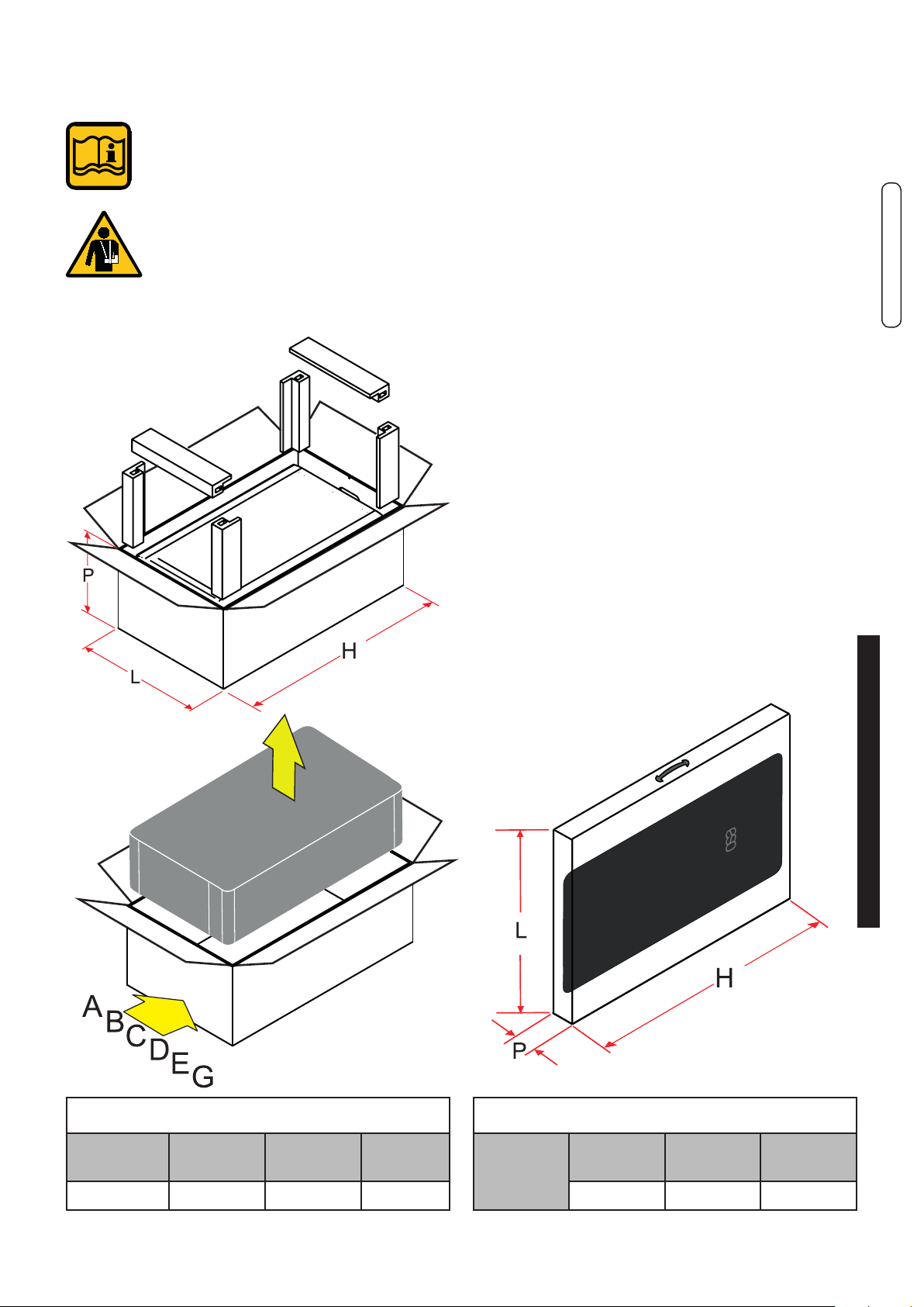
3.4 - PACKAGING
The OSA boiler is supplied completely assembled
in a sturdy cardboard box.
After having removed the appliance from
the packaging, make sure that the supply
is complete and undamaged.
The packaging elements (cardboard
box, straps, plastic bags, etc.) must be
kept out of the reach of children as
they are potential sources of danger.
Unical AG S.p.A. will not be held liable
1
for damage to persons, animals or objects due to
failure to comply with the instruction above.
As well as the appliance, the packaging contains:
A DOCUMENTATION ENVELOPE
- User operating instructions booklet
- Instruction booklet for the installer and
maintenance engineer
- Warranty
- 2 Spare parts form
- Certicate of conformity
- Gas conversion label
B - Connection predisposition paper template
D - Chimney spacer
E - Bracket for xing
F - Uy BOX
G - Outer sensor + Remote temperature sensor
ENGLISH
2
BOILER
OSA S P
Depth
200 mm 540 mm 1010 mm
L
Width
H
Height
3
SHELL
OSA S P
L
Depth
62 mm 592 mm 1000 mm
Width
H
Height
Installation Instructions
17

3.5 - POSITIONING THE BOILER
When choosing the place of the installation of the
appliance, follow the safety instructions below:
- Place the appliance in rooms protected from frost.
- Avoid installation in rooms with a corrosive or very
dusty atmosphere.
- The appliance must only be installed on a vertical
and solid wall which can support its weight.
- The wall must not be made of ammable material.
Since the temperature of the wall on which the boiler is installed and the temperature of the coaxial
exhaust pipe do not exceed, in normal operating
conditions, a room temperature beyond 60 K, it is
not necessary to observe the minimum distances
from ammable walls.
For boilers with double intake and exhaust pipes, in
the event of crossing ammable walls, insert insulation between the wall and the ue gas exhaust pipe.
OSA S 24 - OSA S 28 - OSA S 35
Clearance
18

3.6 - FLUE GAS EXHAUST PIPE CONNECTION
FOR BOILERS WITH FORCED DRAUGHT
To connect the ue gas exhaust pipe, local and national standards must be observed
In the event the boiler is replaced, ALWAYS re-
C13x C13
% Slope towards inlet = 3%
TOTAL LENGTH (LA intake + L Exhaust)
COAXIAL Ø60/100 DOUBLE Ø80
FROM [m] TO [m] FROM [m] TO [m]
1 5,5 1 + 1
COAXIAL Ø80/125 DOUBLE Ø60
FROM [m] TO [m] FROM [m] TO [m]
1 8 1 + 1
Distance between air
inlet pipe and ue gas
exhaust pipe: min 250
mm - max 500
Horizontal exhaust and intake terminals directed
outside via coaxial or double pipes..
40
(20A+20S)
20
(10A+10S)
place the ue gas pipe as well.
The boiler is type approved for the exhaust congurations listed below:
C43x C43
ENGLISH
Collective chimney ue system, consisting of two
pipes, one for combustion air intake and the other
one for combustion products evacuation, coaxial
or double.
C53x C53
C33x C33
TOTAL LENGTH (LA intake + L Exhaust)
COAXIAL Ø60/100 DOUBLE Ø80
FROM [m] TO [m] FROM [m] TO [m]
1 7 0,5 + 0,5
COAXIAL Ø80/125 DOUBLE Ø60
FROM [m] TO [m] FROM [m] TO [m]
1 9 1 + 1
ertical exhaust and intake terminals directed out-
side via coaxial or double pipes.
40
(20A+20S)
20
(10A+10S)
C53
NOT ALLOWED C53
TOTAL LENGTH (LA intake + L Exhaust)
DOUBLE Ø80 DOUBLE Ø60
FROM [m] TO [m] FROM [m] TOA [m]
1 + 1
40
(max 30 S)
1 + 1
(max 15 S)
20
Separate combustion air intake and combustion
products evacuation pipes.
These pipes can discharge into areas with different
pressure.
Installation Instructions
19

C63x C63
Boiler intended for connection to a combustion air
intake and combustion products evacuation system,
approved and sold separately
ATTENTION:
The ue must comply with standards
in force.
C83x C83
B23P
TOTAL LENGTH (LS)
DOUBLE Ø80
FROM [m] TO [m]
1 30
Connection to a combustion products evacuation
pipe outside the room; the combustion air is taken directly from the room where the appliance is
installed.
Connection to a terminal for combustion air intake
and ue gas exhaust via a single or collective
chimney.
C93x C93
Air / ue gas through concentric pipes in the boiler
room and single pipes in the chimney (combustion
air with counterlow in the chimney)
ATTENTION:
(*) Values in the MT018 available on the website.
For the type of connection B23P the
room follows the same installation rules
for boilers with natural draught.
CAUTION
LT total length is a reference value
for the dimensioning of the ducts of A
(intake) and S (Exhaust). Subtracting
the values of LT reported, at values of
bends* / terminals* / extensions* you
get the value:
if > 0 = OK - POSSIBLE conguration
if < 0 = NO - WRONG conguration
Please note:
These values relate to exhausts/
made by means of rigid pipes and
smooth original UNICAL.
20
NOTE!
For more information
See Technical Info
from site indicated at pag. 2

GENERAL INFORMATION ON THE FLUE GAS EXHAUST SYSTEM
Rear smoke
outlet
not possible
ENGLISH
Rubber sealing caps
(Remove according to the type
Exhaust used:
HIGHER
- Split (remove both)
- Coaxial (leave only one shown)
REAR NOT VISIBLE
(rear in the boiler)
installation instructions in the kit.
it is possible only with coax
(Leave 2 above).
(+) Adapter for double systems
Departure Coaxial
It is recommended to only use original
Unical exhaust pipes.
The supplier will have no contractual
or extra-contractual liability for damage
caused due to incorrect installation and
use and in any case failure to comply
with the instructions provided by the
manufacturer.
NOTE!
For further details relating to pressure drops of
the individual components, for information on
standards, rules and regulations for proper ue
gas exhaust, refer to the "Technical Information"
section on the boiler page of the www.unicalag.
it website
Installation Instructions
21

3.7 - CONNECTION
G GAS 3/4’’
Danger!
The gas connection must be carried out
only by a qualied installer who must respect and apply that foreseen by relevant
laws in force in the local prescriptions of
the supply company. Incorrect installation
can cause damage to persons, animals
and objects for which the manufacturer
cannot be held responsible.
If you smell gas:
a) Do not operate electric switches,
the telephone or any other object that
may cause sparks;
b) Immediately open doors and
windows to create air current
to purify the room;
c) Shut the gas cocks.
M FLOW 3/4’’
R RETURN 3/4’’
Condensation drain
The boiler, during the combustion process, produces condensation that, through pipe “A”, ows
into the trap.
The condensation that forms inside the boiler ows
into a suitable drain via pipe “B”.
Danger!
Before commissioning the appliance:
- check that the trap is assembled
properly
- ll the trap and check that
the condensation is drained properly
If the appliance is used with an empty
condensation drain trap, there is an
intoxication hazard due to the release
of exhaust gasses.
C HOT 1/2’’
F COLD 1/2’’
Sc BOILER DRAIN
S.cond CONDENSATION DRAIN
Rc FILLING VALVE
Svs SAFETY VALVE DRAIN
Provide a drain pipe with funnel and a
trap that lead to a suitable drain, in correspondence of Svs.
This drainage must be controlled on
sight.
If this precaution is not taken, triggering of the safety valve can cause damage to persons, animals and objects,
for which the manufacturer cannot be
held responsible.
Aves
Connection for additional expansion
vessel.
22
The mains pressure must be within 1 and 3
bar (in the event of greater pressure install
a pressure reducer).
Condensation outlet, pipe to be connected to
the drainage system

The connection between the appliance
and the domestic waste system must
be made in compliance with the specic
reference standards.
3.8 - FILLING THE SYSTEM
Attention!
Do not mix the heating water with incorrect concentrations of antifreeze
or anti-corrosion substances! This
could damage the gaskets and cause
noise during operation.
When the system connections have been completed,
the circuit can be lled.
This operation must be performed carefully, respecting the following phases:
- open the radiator vent valves and make sure the
automatic valve is working properly in the boiler.
- ONLY FOR FIRST FILL - normally the lling is
automatic - open the lling tap gradually Rc (mediante cacciavite) making sure that the automatic
air release valves installed on the system work
properly.
- close the radiator air release valves as soon as
water comes out.
- check the pressure gauge U-y until pressure
reaches approximately 0.8/1 bar.
- close the lling tap Rc and bleed air once again
through the radiator air release valves.
- make sure that all the connections are watertight.
- after commissioning the boiler (see par. 3.10) and
bringing the system to the operating temperature,
stop the boiler and repeat the air bleed operations.
- let the system cool down and, if necessary, return
the water pressure to 0.8/1 bar.
(See par. 4.5).
NOTE!
For more information
See Technical Info
from site indicated at pag. 2
ENGLISH
Note: The rst ll of the boiler must
be made manually.
FILLING VALVE
Screw in load position
LOAD
FILLING VALVE
Screw in position of
NORMAL OPERATION.
Unical will not be held liable for damage to persons, animals or objects
due to failure to comply with the above
instruction.
Installation Instructions
Rc
The lling valve RC is positioned
behind the siphon.
23

3.9 - ELECTRICAL CONNECTIONS
Danger!
Only a qualied technician may perform the electrical installation.
Before performing connections or
any type of operation on electrical parts, always
disconnect electrical power and make sure that
it cannot be reconnected accidentally.
The external connections have to be made on the
GATEWAY (connector Y3), the cable exits wil be
made in groves on cover A.
OT/TA = ON-OFF room thermostat (*)
OT (OpenTherm) is not enabled
- Arranged on GATEWAY connector, Y 3 5-6.
Remove the jumper and connect the wires of
the room thermostat between terminals.
(*) Optional
SA = Room sensor supplied
- Arranged on GATEWAY connector, Y3 9-10,
Remove the bridge between terminals 5-6.
24

SE = Outside sensor supplied
SHC = Multifunction module (*)
ENGLISH
- Arranged on GATEWAY connector, Y3 7-8.
Electric power supply connection
Modulation
Board
INSIDE
BOILER
- Arranged on GATEWAY connector, Y3 4-3.
The boiler is equipped with a power
cable, boiler installation requires electric al connection to the mains power
supply. This connection must be made
up to standard, as required the regulations in force.
Remember that a bipolar switch must
be installed on the boiler power line
with over 3 mm between contacts, easy
to access, making maintenance quick
and safe.
The power cable must be replaced
by technical personnel authorised by
UNICAL AG S.p.A., using original spare
parts only. Failure to comply with the
above can jeopardise the safety of the
appliance.
Installation Instructions
If necessary the shield of the sensor
cable, can be connected to the terminal. (Ground connections - modulation
board).
See par. 4.5 positioning on the board
(*) Optional
25

3.10 - COMMISSIONING
Commissioning must be done by professionally qualied personnel. Unical AG
S.p.A. will not be held liable for damage
to persons, animals or objects due to
does the installation meet the specic standards and regulations in force, both relating to the
gas part as well as the electrical part?
do the combustion air intake and ue gas exhaust take place properly according to what is
dened by the specic rules and regulations in force?
is the fuel supply system sized according to the capacity required by the boiler?
Is it equipped with all safety and control devices required by the standards in force?
is the power supply of the boiler 230V - 50Hz?
has the system been lled with water (approximately 0.8/1 bar pressure on the pressure gauge
with the pump stopped)?
Has the condensation drain trap been lled with water as indicated in chapter 3.7?
are any system shut-off gate valves open?
does the gas to be used correspond to the boiler calibration gas?: otherwise, perform the boiler
conversion in order to use the gas available (see section: 4.3”);
this operation must be carried out by technical staff qualied in compliance with the standards in force;
is the gas supply valve open?
failure to comply with the above instruction.
Before commissioning the boiler, check that:
has the system been checked for gas leaks?
is the outside main switch ON?
is the system safety valve efcient and is it connected to the drains?
is the condensation drain trap connected to the drains?
has the system been checked for water leaks?
are the ventilation conditions and minimum distances to perform any maintenance
ensured?
have the GAS, HEATING and DOMESTIC HOT WATER pipes been cleaned thoroughly with
products suitable for each circuit?
has a surveillance and protection system against gas leaks been installed? (Optional)
are the system pipes NOT used as the electrical system earthing?
has the system been sized properly bearing in mind the radiator pressure drops?
thermostatic valves, radiator stop valves
has the operator been trained and has the documentation been supplied?
26
Please tick the operations performed
Switching boiler on and off
NOTE!
For more information
See Technical Info
from site indicated at pag. 2

3.11 - MEASUREMENT OF COMBUSTION EFFICIENCY DURING INSTALLATION
3.11.1- ACTIVATION OF THE CALIBRATION
FUNCTION
ATTENTION!
Function reserved for Authorised
Assistance Centres only.
ENGLISH
3
1 - Inserit psw and select the function
4
4 - Activation
2
2 - Activation
3 - Available choice generator indicated by
es: usually 1 / modulex 1÷8
Installation Instructions
27

5 - Generator active modulation max 100%.
6 - Change the % modulation to minimum
10%, and select the generator
7 - Generator active modulation min.
3.11.2 - POSITIONING THE PROBES
To determine the combustion efciency
one must make the following measurements:
- measurement of the combustion air temperature
taken in the relevant hole 2.
COAXIAL PIPES
A
Air
probe
1
Air
probe
2
Flue gas
probe
SEPARATE PIPES
B
Flue gas
probe
8 - Disable function Chimney sweep
- measurement of the ue gas temperature and
content of CO2 taken in the relevant hole 1.
Take the measurements with the generator in
steady state conditions (see par. 3.11.1).
PIPES Ø 80 TYPE B23
C
1
Air
probe
1
2
2
Flue gas
probe
28
NOTE:
Do not enter immediately the analyzer
probe in the sampling point, to avoid the
saturation analyzer.
It’s important to perform also the
combustion air of combustion analysis,
(Observing that the concentration
of oxygen falls O
tolerance 0.2 - 0.4%).
This is to prevent there being any
recirculation of the fumes.
= 20.8%
2

3.12 - ADJUSTING THE BURNER
Check the levels of CO2 often,
especially with low ow rates. They
refer to the boiler with a closed
combustion chamber.
PRESSURE - FLOW RATES TABLE
OSA S 24
Type of
Gas
Nat. gas (G20) 2,96 - 23,0 3 - 23,4 20 - - - 9,2 (*) 9,2 (*) 0,32 m³/h 2,48 m³/h -
Propane (G31) 2,96 - 23,0 3 - 23,4 37 - - - 10,5(+) 10,5(+) 0,23 kg/h 1,82 kg/h -
(*) 9,0 ± 9,8 Acceptable range for G20 (+) 10,0 ± 11,0 Acceptable range for G31
OSA S 28
Type of
Gas
Gas nat. (G20) 4,3 - 27,3 4,4 - 28,0 20 - - - 9,2 (*) 9,3 (*) 0,47 m³/h 2,96 m³/h -
Propano (G31) 4,3 - 27,3 4,4 - 28,0 37 - - - 10,4(+) 10,5(+) 0,34 kg/h 2,17 kg/h -
(*) 9,0 ± 9,8 Acceptable range for G20 (+) 10,0 ± 11,0 Acceptable range for G31
Effective
Output
[kW]
Effective
Output
[kW]
Heating
Thermal
[kW]
Capacity
Heating
Thermal
[kW]
Capacity
Supply
Press.
[mbar]
Supply
Press.
[mbar]
Fan
speed
[rpm]
min max min max min max
Fan
speed
[rpm]
min max min max min max
Collector
diaphragm
[Ø/n.
holes]
Collector
diaphragm
[Ø/n.
holes]
CO2 levels
[%]
CO2 levels
[%]
Con-
sumption
Con-
sumption
Con-
sumption
Con-
sumption
Start-up
power
IG [%]
Start-up
power
IG [%]
ENGLISH
OSA S 35
Type of
Gas
Gas nat. (G20) 4,3 - 32,2 4,4 - 33,0 20 - - - 9,2 (*) 9,3 (*) 0,47 m³/h 3,49 m³/h -
Propano (G31) 4,3 - 32,2 4,4 - 33,0 37 - - - 10,4(+) 10,5(+) 0,34 kg/h 2,56 kg/h -
(*) 9,0 ± 9,8 Acceptable range for G20 (+) 10,0 ± 11,0 Acceptable range for G31
Effective
Output
[kW]
Heating
Thermal
[kW]
Capacity
Supply
Press.
[mbar]
Fan
speed
[rpm]
min max min max min max
Collector
diaphragm
[Ø/n.
holes]
CO2 levels
[%]
Con-
sumption
Con-
sumption
If the CO2 level detected is out of recommended range, verify the integrity of the electrode.
In case of necessity replace the electrode.
If the problem persists you can use the functions described below.
Start-up
power
IG [%]
Installation Instructions
29

3.12.1 - COMBUSTION ADJUSTMENT FUNCTION ACTIVATION
This function allows a partial adjustment of the
value on the following modulation points:
CO
2
Maximum output 100 %
Start-up output xx %
Minimum output 0 %
After Auto Calibration GAC par. 4.3.1
Perform combustion adjustment calibration
as indicated:
If the CO2 value is not as expected, when
appears box (+/-), you can retouch the value of the
Maximum Power.
If the desired value has been reached, proceed to
the next level by pressing: Ignition
If the CO2 value is not as expected, when
appears box (+/-), you can retouch the value of the
Minimum Power.
If the CO2 value is not as expected, when
appears box (+/-), you can retouch the value of
the Ignition. If the desired value has been reached,
proceed to the next level by pressing: Minimum
The combustion adjustment is nished.
30

3.12.3 - ADAPTATION OF THE POWER TO THE HEATING SYSTEM
ATTENTION!
Function reserved for Authorised
Assistance Centres only.
It is possible to adjust the maximum thermal capacity
in heating mode, by decreasing the burner pressure
value.
E.g.: OSA S 24
to decrease the output of the
boiler to 18 kW, edit parameter
792 on Uy BOX (about 70)
E.g.: OSA S 28
to decrease the output of the
boiler to 20 kW, edit parameter
792 on Uy BOX (about 65)
E.g.: OSA S 35
to decrease the output of the
boiler to 24 kW, edit parameter
792 on Uy BOX (about 68)
.
.
.
The user is NOT authorised to activate the function described below.
Act on parameter 792 (par. 4.2 SE parameters list)
to achieve the value corresponding to the desired
output.
ENGLISH
parameter 792 (HP %)
Installation Instructions
31

4
INSPECTIONS AND MAINTENANCE
Inspections and maintenance performed
professionally and according to a regular
schedule, as well as the use of original
spare parts, are of the utmost importance
for fault-free operation of the boiler and
to guarantee its long life.
Yearly maintenance of the appliance is
mandatory in compliance with Laws in
force.
4.1 - INSPECTION AND MAINTE NANCE INSTRUCTIONS
To assure long-term functioning of your appliance
and to avoid altering its approved status, only original
Unical AG S.p.A. spare parts must be used.
If a component needs to be replaced:
• Disconnect the appliance from the electrical mains
and make sure that it cannot be reconnected
accidentally.
• Close the gas shut-off valve upstream the boiler.
• If needed, and depending on the intervention to
be carried out, close any shut-off valves on the
ow and return line of the heating system, as well
as the cold water inlet valve.
Failure to perform Inspections and Maintenance can entail material and personal
damage.
• Remove the front casing from the appliance.
Once all maintenance operations are complete
resume boiler operation
• Open the heating ow and return pipes, as well
as the cold water inlet valve (if closed previously).
• Vent and, if necessary, restore the heating pressure until reaching a pressure of 0.8/1.0 bar.
• Open the gas shut-off valve.
• Switch the boiler back on.
• Make sure the appliance is gas tight and watertight.
• Remount the front casing of the appliance.
TABLE OF RESISTANCE VALUES, ACCORDING TO THE TEMPERATURE, TO THE HEATING PROBE 11 (SR)
AND TO THE DOMESTIC HOT WATER PROBE 1 (SS) AND ANY HEATING RETURN PROBE 22 (SRR) see par. 4.5.
T°C 0 1 2 3 4 5 6 7 8 9
0 32755 31137 29607 28161 26795 25502 24278 23121 22025 20987
10 20003 19072 18189 17351 16557 15803 15088 14410 13765 13153
20 12571 12019 11493 10994 10519 10067 9636 9227 8837 8466
30 8112 7775 7454 7147 6855 6577 6311 6057 5815 5584
40 5363 5152 4951 4758 4574 4398 4230 4069 3915 3768
50 3627 3491 3362 3238 3119 3006 2897 2792 2692 2596
60 2504 2415 2330 2249 2171 2096 2023 1954 1888 1824
70 1762 1703 1646 1592 1539 1488 1440 1393 1348 1304
80 1263 1222 1183 1146 1110 1075 1042 1010 979 949
90 920 892 865 839 814 790 766 744 722 701
Relation between the temperature (°C) and the nom. resistance (Ohm) of the heating probe SR and of the domestic hot
water probe SS
Example: At 25°C, the nominal resistance is 10067 Ohm At 90°C,the nominal resistance is 920 Ohm
32

4.1.1- CONTROL PANEL Uy BOX
Uy BOX is hidden inside the boiler, to
access it, rotate as indicated.
General Operating Instructions for UyBOX, are contained in specic manual
provided with the boiler.
This section only lists the steps requi-
red to
Adjustment / maintenance of the boiler:
- Chimney sweep function (Par. 3.11.1)
- Calibration (Par. 3.12.1)
- Edit parameters (Par. 4.2)
- Automatic calibration GAC
Adaptive Calibration Gas (Par. 4.3.1)
ENGLISH
Maintenance instructions
33

ROUTINE YEARLY VERIFICATION OPERATIONS
COMPONENT: VERIFY: CONTROL/INTERVENTION
METHOD:
FL
(domestic hot water
Is the minimum domestic hot water
ow rate 3 l/min.?
The burner must ignite with an
intake above or equal to: 3 l/min.
priority ow switch ( 2 )
VG
(Gas valve) ( 3 )
SR (heating sensor)( 11 )
SS (domestic hot water sensor)
( 1 )
SSR (return sensor) ( 22 )
E ACC/RIV. (ignition/detection
electrode) ( 4 )
TL (anti-overheating
limit thermostat) ( 10 )
DK (safety pressure switch
against water deciency) ( 13 )
Does the valve modulate properly? Open a hot water tap at maxi-
mum ow rate and then at minimum. Make sure that the ame
modulates.
Do the sensors maintain the
original characteristics?
12571 ohm at 20° C / 1762 ohm
at 70° C.
Measurement to be taken with
the wires disconnected (see
table Res/Temp).
Does the discharge of sparks before
putting the boiler in safe conditions last
less than 10 sec.?
Does the TL put the boiler in safety
conditions when overheating?
Detach the electrode ionisation
wire and check the securing
time.
Heat the TL until it intervenes
at 95°C and check that it intervenes at 95°.
Does the pressure switch block the
boiler
if the water pressure is below 0.4 bar?
Without request: close the shutoff valves of the heating circuit,
open the drain valve to make the
water pressure decrease. Before
pressurising again, check the
pressure of the expansion vessel.
Expansion vessel ( 8 ) Does the vessel contain the right
amount
of air?
Check the pressure in expansion
vessel (1 bar when the boiler
is empty). Pressurise the boiler
(open the pump automatic vent
valve). Open the heating circuit
closing valves.
Condensation drain trap (26) Has the trap got deposits on the
Clean the trap with water.
bottom?
Domestic hot water ow rate Filter in cold water inlet ( 2 ) Clean the lter with limescale
remover.
Heat exchanger body ( 24 ) 1) Measure the Thermal Capacity
using a meter and compare the value with that contained in table 3.12.
The data measured indicates if the
exchanger needs cleaning.
It is recommended to use the
products purposely created by
Unical (see system protection
ACCESSORIES sect. in the
domestic price list), being careful to wash the area with most
2) Check that the space between
the rungs of the exchanger are not
clogged
Burner ( 5 ) Check the state of cleanliness of the
burner mesh
rungs rst (lowest part visible
from above) and then the upper
part if necessary.
Remove any deposits using
compressed air, blowing from
the mesh side.
( Num ) = see key Par. 2.2
34

4.2 - PROGRAMMING OF THE OPERATION PARAMETERS
WARNING!
Function reserved exclusively to
authorized service centers.
ENGLISH
At every boiler lighting UFLY scans devices, if new
devices are recognized, such as:
hcm /
bcm
shc
bmm
Heating / Burner Control Manager
Slave Heating Controller
Multifunction module
Burner Modul Manager
They are displayed on the next screen, and is
prompted to save the new conguration.
Icon scanning devices
icon save new conguration
Device detected
Not installed device
previously recognized device, but not detected.
Maintenance instructions
35

To change the parameters is required password.
Parametri
Code Description
803
322
787
789
807
792
31
36
Enabled Services:
0: CH & DHW disabled
1: CH enabled
2: DHW enabled
3: CH & DHW enabled
Pump: Post-circulation
0: overrun 5 min.
1: continuous
Outdoor minimum
temp °C
Night shift °C
0: T.A.
5÷30: Value night shift
ACS Preheating
CH: Modulation max
CH#1 Minimum Set
point
Set. Min.
3 0 3
0 0 1
10 0 30
0 0/5 30
0 0 1
100 0 100
30 20 45
Max.
39
650
385
48
832
CH#1 Max. Set point
ACS Set point Min.
ACS Set point Max.
CH#1 Set point °C
Access Code (#)
85 50 85
35 25 45
60 50 65
70 20 85
0 0 199
To change the following parameters you must
enable the access code.
778
341
313
312
775
309
771
Burner:
0: G20 - 1 GPL
Pump: Minimum
Control
Pump: Maximum
Control
Pump: temp. diff. °C
Valvola Dev.: Stroke
time sec.
System congurations:
1: W1
2: W2
3: W3
4: W4
Sensore pressione
Acqua
0: assente - 1 presente
0 0 1
-- 0 100
-- 20 100
-- 5 20
-- 0 6
-- 1 4
-- 0 1

896
806
848
483
672
2590
619
Unit:
0 = °C / bar
1 = °Fahrenheit / PSI
Frequency:
0: 50 Hz - 1: 60 Hz
Dis. local setpoint:
0: bidirectional
1: Only by remote
Temp. different. Max
Min modulation
CH/ACS
Burner power
Modulation and ignition
0 0 1
0 0 1
0 0 1
1 0 1
0 0 100
-- 0 9
-- 10 70
346
319
353
354
478
323
324
325
(#) Enable (insert value)
to change parameter
(*) ( x 10 + 750) = rpm x 100
(**) ( x 10 + 5000) = rpm x 100
Fan min speed
fan max speed
Regolation
Proportional
Regolation Integrative
Regolation Derivative
ACS PID:Proportional
ACS PID:Integrative
ACS PID:Derivative
(*) 0 199
(**) 0 199
-- 1 20
-- 1 20
-- 1 20
-- 1 20
-- 1 50
--
1 20
ENGLISH
Historical Error
Clean display Error with CLEAR .
Maintenance instructions
37

4.3 - ADAPTATION
TO THE USE OF OTHER GAS
The boilers are produced for the type of gas specically requested upon ordering.
Gas Conversion
DANGER!
The conversion for the operation of
the boiler with a type of gas other
than that specically required in the
order, must be performed by pro-
fessionally qualied personnel, in
compliance with the standards and
regulations in force.
The manufacturer cannot be held
liable for any damage resulting from
a conversion operation that is incorrect or not performed in compliance
with the laws in force and/or with the
instructions given.
ATTENTION!
After performing the conversion for
the operation of the boiler with a type
of gas (e.g. propane gas) other than
that specically requested when or-
dering, the appliance will only work
with this new type of gas.
ATTENTION!
Indications for propane gas-fired
appliances
Make sure that the gas tank has been
deaerated before installing the appli-
ance.
For state-of-the-art deaeration of the
tank, contact the LPG supplier or a
person qualied in compliance with
law.
If the tank has not been profession-
ally deaerated, ignition problems
could arise.
In that case, contact the supplier of
the LPG tank.
NOTE!
For more information
See Technical Info
from site indicated at pag. 2
In order to change the gas one must change
the Factory parameter:
PARAMETER par 4.2
CODE GAS NAT. PROPANE
778 0 1
Once the 778 parameter has been
edited one must perform the GAC
automatic calibration (Gas Adaptive
Calibration) Chapter 4.3.1
- when the conversion is complete, ll in the
information required on the label supplied in
the documentation envelope and apply it next
to the technical data label of the boiler.
EXAMPLE OF COMPILATION
38

4.3.1 - GAC AUTOMATIC CALIBRATION
One can perform the GAC in domestic hot water
mode as well.
Make sure that there are no heating requests present and that all the valves of the heating system
are open.
If during this stage one wishes to disperse the heat
on the domestic hot water circuit, open at least 2 hot
water taps (ONLY AFTER HAVING ACTIVATED THE
GAC FUNCTION).
WARNING!
Function reserved exclusively to
authorized service centers.
ENGLISH
Start Calibration phase - Wait:
Step 1 = Calibration Maximum Power
Step 2 = Calibration Power Start
Step 3 = Calibration Minimum Power.
Maintenance instructions
39

Step 1: CALIBRATION MAX POWER
Step 3: CALIBRATION MIN POWER
Step 2: CALIBRATION POWER START
The automatic calibration is completed.
To perform the calibration adjustment of combustion, see par. 3.12.1.
40

(This page is intentionally left blank)
ENGLISH
Maintenance instructions
41

KEY
BOARDBMM
A1.....A9 Services connectors
ALIM.P.sup Supply.PumpExtra
CMP Control modulating Pump
E.ACC./RIL Ignition/detection electrode
EVCI (*) Caricamento Impianto (Only OSA S)
FLS Domestichotwaterrequestowswitch
MEMORY
Memory
CARD
42

4.4 - WIRING DIAGRAM
Practical connection board
ENGLISH
MVD Diverter valve motor
MDV (**) Controlpredispositiondiverter(externalwater
heater)onlyHeatingboilers
PM Circolatore Modulante
SPI Pressure Sensor System
SR Flowheatingsensor
SRR Returnheatingsensor
SS
TL Limitthermostat
TLC Fluegascollectorlimitthermostat
Domestichotwaterprobe(Pred.forRmodels)
VG Gas valve
VM (A) Soupply modulating fan
VM(R) Rilev./Reg.ModulatingFun
SchedaGATEWAY
Y1....Y3 Services connectors
230V-50Hz Boiler Supply
EXT DEVICE Externaldevices:SHC(eBUS+/eBUS-)
SA TerminalRoomsensor
SE Terminal Outer sensor
OT/TA TerminalTAon-off/OT disabled)
UFLY
connection
U-yBOXsupply
Maintenance instructions
43
4.5 - ERROR CODES
Failure that causes the stop of the boiler:
- The error code is displayed, the boiler is in lock.
After resolving the fault press Reset to restart the
boiler.
ERROR CODES (FAULT) ( Num ) = see key Par. 2.2
CODE
01
04
06
08
09
10
11
12
13
14
15
DESCRIPTION SOLUTIONS
SAFETY THERMOSTAT
Intervention of the safety thermostat (10)
BLOCK
No gas or failed burner ignition
High Temperature
Boiler temperature too high
Water Decency
Insufcient water pressure and consequent
intervention of the minimum water pressure
- pressure switch ( 13 ).
Outer Sensor Check the wiring, if needed replace outer sensor
Internal failure
Parasite Flame
Flame detected upon ignition
Heating Sensor (11)
Heating sensor fault
Domestic Hot Water Sensor
Domestic hot water sensor fault (1)
Inlet temperature Sensor
(SRR)
Water circulation insufcent
Primary circuit water circulation insufcient
(∆t > 35° C)
Failure that could NOT cause stop of the boiler:
Error code is displayed, the boiler is in CH
-
demand, Icon Reset (note that was detected
a fault even if the fault was temporary.
Is therefore necessary always push reset to
clear the display’ ‘‘error’’
Press Reset and/or check that the thermostat or
its connections are not interrupted.
Check the gas supply or that the ignition/detection
electrode is working properly (4).
Check pump operation and if needed
clean the exchanger (24)
Fill the heating circuit as described in chap. 3.8 and
wait for the values to return within default limits.
If needed, check the electrical connections and
replace the minimum water pressure switch.
Check the wiring of the Ign/Det. electrode and remove any oxidation. Check for humidity between
drain wire and ceramic, if necessary, replace the
electrode, press the unblock key, if the anomaly
persists, replace the electrode (4).
Check the efciency of the sensor (see table Res/
Temp) (Par.4) or its connections.
Check the efciency of the sensor (see table Res/
Temp) (Par.4) or its connections..
Check the efciency of the sensor / and replace it
Check pump operation (12) and speed - remove
any heating system obstructions - clean the scaled
domestic hot water exchanger
44
16
Exchanger Freezing ( 24 )
Exchanger freezing is detected If the heating
sensor detects a temperature below 2° C,
burner ignition is inhibited until the sensor
detects a temperature above 5°C
20 Parasite Flame
Flame detected after swtich-off
24
Speed out of control
Check fan operation (18) and the con-
nections
25
26
28
30
31
32
38
44
45
47
49
50
56
57
58
60
62
66
74
75
Exhaust smoke overheating
Speed out of control
Alteration of the fan speed; the speed is
above that requested
Scambiatore Ostruito
Service Parameter
Service parameters altered due to possible
electromagnetic interferences.
System conguration invalid or
corrupted
Low line voltage Correction: if the line voltage is <190 Vac: the
Factory Parameters
Alteration of the factory parameters due to
possible electromagnetic interferences.
Water sensor pressure
detected if the pressure Transducer is
present
Water Overheater
detected if the H
present with pressure > 2.5 bar; it is reset
automatically when H
Communication error
HCM, SHC: host controller missing
Room1: temperature sensor
Host controller missing
Burners NOT detected
Global ow temperature sensor
Date and Time not valid
Actuators SGV
Missing calibration
Temp. sensors swap
Temperature slope exceeds the limit
O pressure Transducer is
2
O pressure < 2 bar
2
Disconnect the from the power supply, close the
gas valve, defrost the exchanger carefully.
Check the wiring and for any leaks from the
gas valve (3), if needed replace the gas valve.
Check fan operation (18) and the connections
ENGLISH
Check fan operation (18) and the connections
Reset and via Uy restore the altered parameters
line voltage is really below the minimum limit,
otherwise the line monitor error: replace BMM
Press RESET; if the anomaly persists, replace
the board.
Wait for the values to return to default limits / Replace the Transducer
Wait for the values to return to default limits /
Replace the Transducer
Maintenance instructions
45

94
95
99
100
101
102
103
Gas valve wiring
Frequent loss of ame
Internal error
General Lockout not listed
Ignition failure
Short circuit of the iono electrode
Gas valve open delay
46

4.5.1 - FILL THE SYSTEM
By pressing reset icon, start the automatic lling,
up to a pressure of 1.2 bar (60 sec. max).
If the system does not reach 1.2 bar pressure within
60 seconds, activate the ll manually by pressing
LOAD icon.
47
4.6 - IMPORTANT NOTES
REPLACING COMPONENTS
Before replacing components one must follow the
notes of chap. 4 "Inspections and maintenance".
To replace the components:
- GAS VALVE
- FAN
- BURNER,
- IGNITION/DETECTION ELECTRODE,
- MODULATION BOARD (in the event the
memory board CANNOT be reused) (*),
GAC calibration is required
MODULATION BOARD
A universal
board
memory
board (*)
B
(*) In the event the memory board can be reused, there is no need to reprogram parameters, settings and automatic calibration.
The memory board is
programmed by default for METHANE
gas operation.
In the event of LPG
operation the 778 parameter must be edited
(Factory parameters),
see (Chap. 4.2).
A
B
Act carefully, pay attention to the insertion direction of the memory board.
48

4.6.1 - SERVICE PANEL
The boiler can be programmed also by
means of the service inner panel.
Remove the screws indicated to extract the panel and turn.
Indications related to programming
with the emergency panel, can be
found at the address indicated on
page 2, or on the user / installation
manual and maintenance of KONE
model boiler.
49


www.unical.eu
ed. 06/15
st.
00336315 - 1
46033 casteldario - mantova - italia - tel. +39 0376 57001 - fax +39 0376 660556
AG S.p.A.
info@unical-ag.com - export@unical-ag.com - www.unical.eu
Also reserves the right to bring those changes that it will hold necessary to it own products or prots, without jeopardizing its essential characteristics.
Unical declines every responsibility for the possible inaccuracies if owed to errors of transcript or press.
 Loading...