


.it AQ
USER OPERATING INSTRUCTIONS
15

2
Dear Customer,
Installation must be performed by skilled personnel, who shall be entirely responsible for nal installation and
consequent proper operation of the installed product. There shall be no liability on the part of the Manufacturer
in case of installation by unqualied person and in case of non-compliance with the general warnings and
installation instructions.
After removing the packaging, check integrity and completeness of the contents. In the event of non compliance,
contact the dealer the heat stove was purchased from.
Prior to installation it is recommended to perform accurate washing of all the system's piping in order to remove
any residues which might aect proper operation of the appliance.
In the event of not using the heat stove for a long time it is recommended to perform the following operations:
• disconnect the power supply plug;
• close water cocks, both of the heating and domestic hot water systems
• if freezing is likely to occur empty the heating and DHW systems.
Extraordinary maintenance of the heat stove must be performed at least once a year. This maintenance must
be scheduled in time with the Technical Support Service, and is borne by the Customer.
For safety it should be remembered that:
• Use of the heat stove by children or unassisted disabled persons is recommended against;
• do not touch the heat stove if you are barefoot and/or with wet or moist parts of the body;
• it is forbidden to modify the safety or adjustment devices without the manufacturer's authorisation or
instructions;
• do not pull, detach, twist the electrical wires coming out of the heat stove, even if it is disconnected from the
power mains;
• avoid blocking or reducing the combustion air duct, which is essential for proper combustion;
• do not leave packaging items within the reach of children or unassisted disabled persons.
ATTENTION!
During the rst couple of heat stove operations, the vapours emitted by the paint may
cause unpleasant smells due to hardening, it is therefore advisable to aerate the room
well and avoid remaining long by the heat stove.
In the event of a re, disconnect electric power, use an approved re extinguisher and, if needed, call
the Fire Brigade. Then contact the Authorised Service Centre.
In congratulating you for purchasing one of our heat stoves, we would like to remind you that pellet heat stoves
are the most innovative heating solution, the result of the most advanced technology with an extremely high
level of workmanship quality. Their neat and elegant design ts well into any room and makes it cosy thanks to
the unique enveloping warmth that re alone is able to give.
This manual will help you to use your heat stove correctly. We therefore recommend to read it carefully before
use.
The heat stoves work exclusively with wood pellet of maximum 6mm diameter, and are tted with an exchanger
that produces approximately 90% yield.
The heat stoves are tted with a timer-thermostat that assures up to 4 weekly on and o-cycles, thus making
control independent. The heat stoves convey heat to the radiators of your system with a thermal power that is
regulated according to the rooms to be heated: just manually set the water temperature of the heating system,
recommended to be at 60°- 75.°
The heat stoves are also tted with tangential fan for spreading hot air, which allows forced convection heating
of the room where it is installed.
Thanks to an optional kit, they also produce continuous domestic hot water in a healthy and safe manner throu-
gh automatic operation, with no need for storage tank.
The heat stoves have been equipped with sophisticated automatisms and control and safety systems that
assure eective and convenient operation.
Installation and maintenance shall be eected by qualied personnel, in compliance with applicable laws in
force and according to the Manufacturer's instructions.
This operating and maintenance manual is an integral part of the product.
Before proceeding with installation, use and maintenance of the product, it is required to carefully read the
instructions in this manual.
This heat stove shall be intended solely for the use for which it was expressly designed. Therefore, any liability
for any harm to people, animals or damage to property for product misuse shall be borne by the user.

3
Technical Specications
Weight
Flue gas exhaust pipe diameter
Air inlet pipe diameter
Water inlet/outlet diameter
Power supply
Min. electric consumption
Min. electric consumption
Tank capacity
Kg 145
80 mm
50 mm
3/4”
230V - 50Hz
90 W
350 W in ignition phase only
17 kg / 26 litres
Approximate dimensions (mm).
221
30
338
121
Ø 50
Ø 80

4
Heat Stove Ignition
ATTENTION!
The burn pot must be cleaned before each
ignition.
Control panel (Fig. 2)
The button is used to ignite or extinguish the
heat stove and to quit programming.
The buttons and are used to adjust the
temperature, for programming display and
functions.
The buttons and are used to adjust the
heating power.
The button is used to set the temperature and
programming functions.
The upper and lower displays are used to view
the various messages.
Control panel signals
Before igniting the heat stove ensure the pellet
tank is lled, the combustion chamber is clean, the
glazed door is closed, the plug is plugged in and
the switch at the rear is in position “1”.
The LED is on when parameter
UT0 1 in the menu is other than
OFF, thus setting the weekly or
daily program.
ATTENTION!
It is recommended to use wooden pellets of
maximum 6 mm diameter, not moist.
Fig. 2
6
1
2
3
4
5
“SET”
LED SYMBOL
DESCRIPTION
The LED is enabled every time
the pellets are being lled.
The LED ashes when the panel
receives a temperature/power
change signal from the infrared
remote control.
The LED is on when the room
temperature reaches the gure
set in the SET Water menu.
The LED ashes to signal that
the user/technician menu is
being accessed, or that the
temperature setting is being
modied.
The LED switches on when
the water circulation pump is in
operation.
1
2
3
4
5
6
Loading pellets into tank
Pellets are loaded into the tank through the specific
door at the back of the stove.
To load pellets, act as follows:
• Open the door at the top;
• Pour the desired amount of pellets into the tank,
with due care (pour enough pellets to guarantee
sufficient stove autonomy);
• Close the door.
LED SYMBOL
DESCRIPTION
5
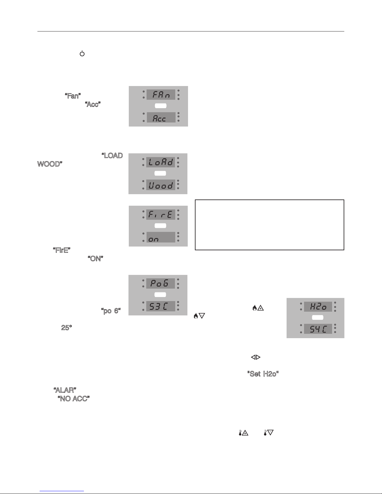
Ignition
Press button for a few seconds until the heat
stove starts.
The upper display will show
the word “Fan” and the lower
display the word “Acc”. During
this stage the appliance will
perform a diagnosis (about
20 seconds) on ue gas
extraction.
The next stage “LOAD
WOOD”, indicates the
pellets are lled and the
igniter will light up to start
the ame.
When the ue gas
temperature is at 50° C
(about 10 minutes) the heat
stove will enable ignition:
the top display will then
read “FirE” while the bottom
display will read “ON”.
After this stage which lasts
5 minutes approximately
the top display will
simultaneously show the
heating power (e.g. “po 6“)
and ambient temperature
(e.g. 25°), while the
lower display will show
the system's ow water
temperature.
If the ame is not correctly ignited after 10 minutes,
the heat stove locks down: the upper display will
read “ALAR” and the lower display will ash the
words “NO ACC”: wait 10 minutes for the cooling
cycle to be completed, open the door, empty the
burn pot and proceed with a new ignition.
PLEASE NOTE:
In the event there should be repeated failed
ignitions, but the pellets are fed properly, there
might be an issue connected to breakage of the
electrical igniter. In this case, while waiting for a
technician to service it, the heat stove may be lit
manually using solid fuel cubes (re starters).
Manual ignition procedure:
• open the door;
• take a cube of solid fuel and place it on the burn
pot together with a handful of pellets;
• strike a match and light the solid fuel inside the
burn pot;
• wait a few minutes, close the door;
• perform the normal ignition procedure.
ATTENTION!
Do not use any ammable liquids for
lighting. During the recharge stage do
not bring the pellet bag in contact with
the hot heat stove.
The heating power is adju-
sted with buttons
and
. It is recommended
to set it at Po 9 for the rst
hours of stove operation.
To adjust water temperature press button
once
only. The upper display will
show the words
"Set H2o"
ashing while the water
temperature is shown on
the lower display.
Adjustment of the work power and water
temperature
Press buttons and to respectively increase and decrease the desired value.
Water temperature range: 30°C - 80°C.
Heat Stove Ignition

6
To extinguish the heat stove
press the button for a few
seconds, until the upper
display reads “OFF”.
To adjust the room
temperature press the
button
twice: the lower
display will show the words
"SET AIR" ashing, whereas
the set temperature is
shown on the upper display.
Use buttons
and to
change the value.
The pellets will immediately stop dropping while
the heat stove will continue operating until the
accumulated heat is completely exhausted, and
go out after 30 minutes at the most.
PLEASE NOTE:
The heat stove is equipped
with an automatism to clean the
burn pot after a certain length
of time: when this happens the
ame is automatically lowered
and the display will read “PUL
FIRE”; after a few minutes the
heat stove will resume normal
operation.
Air temperature range: 7°C-40°C
ATTENTION!
To extinguish the heat stove, do not unplug
it but let the automatic extinction cycle end:
prolonged ue gas exhaust fan operation is
normal and may indicate that the stove is
still hot.
In case of low temperatures, moreover, ue
gas exhaust fan and circulating pump may
still start up for a few minutes with stove
o, in order to prevent possible formation
of ice in the system's pipes. In the event of
a power outage, when the power supply
is restored the heating controller will
expel the residual ue gas, increasing the
extractor's speed and displaying the words
“Cool FIRE”. Upon completing the cooling
cycle, the stove will restart automatically
and go back to the operating mode prior to
the power outage.
Heat stove extinction
Room temperature adjustment
Heat Stove Ignition

7
Chronothermostat
The chronothermostat function is used to program
automatic cycling on and o of the heat stove
throughout the week.
To enter programming hold the button
for
about three seconds, the upper display will
show the parameter “UT01” : press the button
several times and refer to the table below to
program the stove according to your needs. To
exit programming mode at any time press the
button
. The chronothermostat parameters are
as follows:
Parameter
Description
Settable values
UT01
OFF; Day 1, ...,Day7
Chrono enable and disable. Set day of the week
UT02
from 00 to 23
Set current hour
UT03
from 00 to 60
Set current minutes
UT04
Reserved
Set technical parameters
UT05
From 00:00 to 23:50
with 10 minute steps
Adjustment of rst heat
stove ignition time
UT06
From 00:00 to 23:50
with 10 minute steps
Adjustment of rst heat
stove extinction time
UT07
Between on/o for
days from 1 to 7
Selection of days of the
week when rst time is
activated
UT08
From 00:00 to 23:50
with 10 minute steps
Adjustment of second
heat stove ignition time
UT09
From 00:00 to 23:50
with 10 minute steps
Adjustment of second
heat stove extinction
time
UT10
Between on/o for
days from 1 to 7
Selection of days of the
week when second time
is activated
UT11
From 00:00 to 23:50
with 10 minute steps
Adjust third time of
heat stove ignition
UT12
From 00:00 to 23:50
with 10 minute steps
Adjustment of third heat
stove extinction time
UT13
Between on/o for
days from 1 to 7
Selection of days of the
week when third time is
activated
UT14
From 00:00 to 23:50
with 10 minute steps
Adjustment of fourth
heat stove ignition time
UT15
From 00:00 to 23:50
with 10 minute steps
Adjustment of fourth
heat stove extinction
time
UT16
Between on/o for
days from 1 to 7
Selection of days of the
week when fourth time is
activated
Below is the meaning of user parameters in detail:
UT01
Enable and disable/chronothermostat and set
current day.
This parameter is used to set the current day of
the week or disable programming.
Press buttons and to select the desired
value as shown in the following table:
Example:
if today is Thursday you must select “Day 4”,
whereas if you wish to ignite the heat stove
manually (without programming) you must select
“OFF”, in order to disable the chronothermostat.
Press button
to move to the next parameter.
Display
To p
MEANING
Day 1
Day 2
Day 3
Day 4
Day 5
Day 6
Day 7
OFF
Monday
Tuesday
Wednesday
Thursday
Friday
Saturday
Sunday
Chronothermostat o
Parameter
Description
Settable values

8
UT05
Adjustment of rst heat stove ignition time
This parameter indicates the time when you wish
to ignite the heat stove: set the desired time with
buttons and , with 10-minute steps.
Press button to move to the next parameter.
UT06
Adjustment of heat stove extinction time
This parameter indicates the time when you wish
to extinguish the heat stove: set the desired time
with buttons and , with 10-minute steps.
Press button to move to the next parameter.
UT07
Select days of the week
Press the button to select the days of the
week, whereas by pressing button you enable
(ON) or disable (OFF) the heat stove ignition day
as shown in the following table:
Display
top
MEANING
Day 1
Day 2
Day 3
Day 4
Day 5
Day 6
Day 7
Monday
Tuesday
Wednesday
Thursday
Friday
Saturday
Sunday
Display
bottom
ON1/OFF1-Yes or No
ON2/OFF2-Yes or No
ON3/OFF3-Yes or No
ON4/OFF4-Yes or No
ON5/OFF5-Yes or No
ON6/OFF6-Yes or No
ON7/OFF7-Yes or No
In the example below, the heat stove is lit on
Saturday and Sunday only.
Conrm and continue with button
.
In case the stove is controlled by external ther-
mostat, when the thermostat reaches the pre-
set temperature, the heat stove display will read
“ECo TERM”.
Day 1
Mon
o 1
Day 2
Tu e
Day 3
Wed
Day 2
Thur
Day 2
Fri
Day 2
Sat
Day 2
Sun
o 2 o 3
o 4
o 5 on 6
on 7
UT08 UT16
continue as above to set the second, third and
fourth ignition.
ATTENTION!
The room thermostat does not implement
the function of cycling the heat stove on
and o, but sets it to saving mode.
UT02
Set current hour
This parameter is used to set the current hour,
press buttons and to select the current
time.
Press button to move to the next parameter.
UT03
Set current minutes
Press buttons and to adjust the current
minutes.
Press button to move to the next parameter.
UT04
Set technical parameters
Press button to move to the next parameter.
Chronothermostat

9
Remote control
Fig. 3
Fig. 4
The remote control (Fig. 3) is used to adjust water
temperature, power and heat stove ignition/
extinction.
Press key
to ignite the heat stove, the heat
stove automatically enters the start up stage.
Press keys and to adjust water
temperature, while use keys
and to
adjust operation power.
To switch o the heat stove press key
; the
heat stove display will read “OFF”.
To replace the 3 volt battery (CR 2025), located
at the rear of the remote control, prise the cover
open with a screwdriver, replace the battery
complying with its polarity (Fig. 4.)

10
Alarm signals
In the event a heat stove operation fault should
occur, the system informs the user on the type of
fault.
Inspection operations must be carried out by the
user and the Technical Support Centre must only
be contacted in case no solution is found.
Display
To p
Display
Bottom
Type of problem
Solution
ALAR
FAN FAIL
ALAR
DEP FAIL
ALAR
SIC FAIL
ALAR
SIC FAIL
ALAR
PRESS
Flue gas extractor fault or block
Obstructed ue
Pellet tank overheating
Excessive water temperature
It indicates that the system pressure is
lower than 0.5 bar or higher than 2.3 bar
Contact the authorised technical support
centre
Clean the chimney or ensure there are no
obstructed grilles on ue gas exhaust outlet
Reset the pellet safety thermostat on the
rear of the stove. If the problem persists,
contact the authorised service centre.
Reset the water safety thermostat on the
rear of the stove. If the problem persists,
contact the authorised service centre.
Decrease pressure in the system
Fill the system
ALAR
NO ACC
-The heat stove is unable to ignite
-It is the rst ignition
Fill the tank with pellet Repeat ignition
ALAR
NO FIRE
- Heat stove extinction during operation
Fill tank with pellets
ALAR
SOND FUMI
The ue gas probe is broken or discon-
nected from the board
Contact the authorised technical support
centre
ALAR
HOT H20
The water temperature exceeds 90 °C.
The circulation pump is blocked or the
plumbing system is discharging water
Ensure the pump is powered.
Ensure the pump impeller is not seized by
limescale
ALAR
SOND H20
The water probe is interrupted
The water probe is shorting
Ensure the water probe is not disconnected.
Contact the authorised service centre
ALAR
HOT TEMP
The ue gas temperature exceeds 280°C
Flue gas probe fault
Contact the authorised service centre
COOL
FIRE
Power outage
When the power supply is restored, the stove performs a cooling cycle, at the end of
which it will automatically restart
SERV
It indicates that the stove has reached
1300 hours of operation. Extraordinary
maintenance must be performed
Contact the authorised service centre
The following table summarises the alarms, type
of problem and possible solution:
Electrical device faults

11
Electrical device faults
Electrical safety
Should a sudden electrical surge occur (lightning)
the heat stove is protected by a 2.5 A 250V fuse
located at the rear of the heat stove, next to the
power supply cable.
Extract the drawer that contains it and replace it.
ATTENTION!
do not try igniting the heat stove before
the required time, as it might lock down.
In the event of lock turn o the switch at
the rear of the heat stove for 1 minute,
turn it on again and wait 10 minutes
before igniting again.
ATTENTION!
the power outlet where the heat stove is
plugged in must be tted with "earthing
connection according to regulations
in force". The Manufacturer disclaims
any liability for damage to property and
harm to people caused by installation
negligence.
Failed ignition
If no ame develops during the ignition stage or
the ue gas temperature does not reach an adequate level in the time interval set for ignition, the
stove in set to extinction and the display reads
“Alar No Acc”.
Press the "On/O" key to reset the alarm. Wait for
the cooling cycle to be complete, clean the burn
pot and proceed with a new ignition.
Extinction during working phase
This occurs when the stove unexpectedly goes
out during normal operation (for instance be-
cause pellets in the tank have run out or due to a
pellet lling gearmotor fault).
The stove continues operating until it processes
any pellets in the burn pot, after which the display
reads “Alar No Fire” and the stove enters extinc-
tion mode.
Press the "On/O" -----button to reset the alarm.
Wait for the cooling cycle to be complete, clean
the burn pot and proceed with a new ignition.
These alarms remind you that before performing
ignition, one must ensure the burn pot is com-
pletely free, clean and correctly placed.
Power outage
Should there be a power outage for a period
longer than one minute, the heat stove might emit
a minimal amount of smoke in the house: this
does not pose any risk for safety.
When the power supply is restored, the heat stove
will display the words “Cool Fire”.
After completing the cooling cycle, the stove will
automatically restart and go into the work mode
prior to the power outage.

12
System pressure safety
The system pressure is controlled electronically
and must be kept between 0.5 and 2.3 bar. If this
is not so the heat stove goes into alarm mode and
the display will read “Alar Press”.
Check system pressure, holding button for a
few seconds: the upper display will read the gu-
re in bar.
In any case the safety valve prevents exceeding
2.5 bar, by automatically venting the excess water
outside.
pellets
pipes
Fig. 5
Flue gas exhaust safety
A mechanical vacuum pump ensures there is
the right vacuum for proper ue gas exhaust.
Otherwise, in the event of ue obstruction, the
heat stove goes into extinction mode and the
display reads “Alar Dep Fail”.
Pellet temperature safety
In the extremely rare cases where an excessive
temperature occurs inside the tank, the manual
reset pellet safety thermostat triggers an alarm
(Alar Sic Fail) and stops heat stove operation.
The customer must reset the above mentioned
device, which is placed behind the heat stove
( g.5)
Water temperature safety
In the event the water temperature should exceed
a 100 °C threshold, the water safety thermostat is
tripped and sets the stove into extinction mode.
The display will read “Alar Sic Fail”. After waiting
a minimum time required for water cooling, the
user needs to reset said thermostat, located at
the rear of the stove ( g.5).
Manual reset thermostats
Electrical device faults

13
Heat stove cleaning
After burning three-four bags of pellets, open the
lower door and unscrew the two knobs that hold
the inspection pan (Fig. 8);
remove the inspection pan, empty it and only clean
the walls and corners with an ash vacuum cleaner
or suitable tools (Fig. 11).
Fig. 8
Fig. 9
The heat stove needs simple and accurate
cleaning in order to always assure ecient
performance and regular operation.
During internal cleaning of the heat stove the
ue gas fan may be started to prevent spilling
out the ashes. Button and then button must
be pressed to actuate this function. The display
reads “PUL STUF” (stove cleaning). To stop the
fan just press and hold button or wait for a
cleaning cycle to be completed (255 seconds) .
DAILY: remove the burn pot and clean it (g.6)
Fig. 6
Fig. 7
Scraper
PERIODICALLY: perform complete cleaning
of the exchanger every other day. When stove
is cold, operate the exchange duct scraper by
pulling and pushing the lever located between
the front grates, through which the heating air
comes out (g. 7-8).
ATTENTION!
Do not clean the glass during heat stove
operation.
Fit the inspection pan back on and screw the two
knobs back in, ensuring it is hermetically closed.
Close the door again.
Glass cleaning: the ceramic glass of the central
door is cleaned with a damp cloth and a little ash,
rub the glass until completely clean. Suitable
detergents may also be used.
ATTENTION:
in the event of lapsed or inadequate cleaning
the heat stove might have functionality
issues such as:
• poor combustion;
• glass blackening;
• burn pot clogging with accumulated ash
and pellets;
• ash deposit and excessive scaling on the
exchanger leading to poor performance.
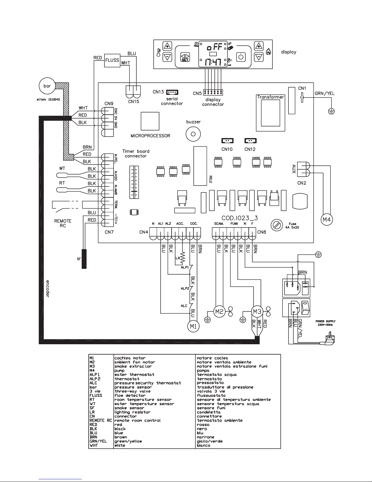
Wiring diagram
230V
Mains
lter

NOTES

00335583 - 1
st
edition 03/15
Unical shall not be held liable for any inaccuracies due to transcription or printing errors.
Furthermore, it reserves the right to modify its products as deemed necessary or useful, without affecting their essential features.
46033 casteldario - mantova - Italy - tel. +39 0376 57001 - telefax +39 0376 660556
info@unical-ag.com - export@unical-ag.com - www.unical.eu
www.unical.eu
 Loading...