

Page 1

ENGLISH
REMOTE CONTROL /
ROOM THERMOSTAT Wireless
INSTALLATION SERVICING AND USER MANUAL
Page 2

2
Attention:
The manufacturer will not be held liable in case of damage to persons, animals or objects resulting from
failure to comply with the instructions contained in the manuals supplied with the boiler.
Index
1 Genera features..................................................................................................................................................3
2 Package Contents .............................................................................................................................................. 3
3 Description buttons and symbols........................................................................................................................3
4 Application ......................................................................................................................................................... 5
5 Installation .......................................................................................................................................................... 6
6 Easy User Guide ................................................................................................................................................7
NOTE!
Tips
for the user
ATTENTION!
Possible dangerous
situation for the product
and the environment
DANGER!
Serious danger
to safety
and health
Page 3

3
1
General Features
2
Package content
No. Description
A 1 EASYr chronotermostat
2 Dowels
2 Batteries
B 1 Bridge OT+
2 Dowels
C 1 Table stant EASY
r
TECHNICAL CHARACTERISTICS AND DEFAULT SETTINGS
Time setting 12:00
Day setting Day 1 = Monday
Operation mode Automatic
Manual mode heating temperature 20°C
Room antifreeze temperature 5°C
Guaranteed average life of batteries 1 year
CU Compensation curve 0 = Deactivated
OF Parallel curve offset 30 °C
P1 Enable DHW programming 0 = Deactivated
P2 Pre-Heating Function 0 = Deactivated
P3 Max. number of daily time bands 6
P4 Heating min. temperature -
P5 Filling the system 0 = Deactivated
P6 Temperature unit of measure
selection
0 = °C
P7 Room temperature reading cor-
rection
0
P8 Telephone contact input operation
selection
0 = Heating
OFF
P9 Manual temperature on closing of
telephone contact input
20°C
EASYr is a remote control with the chronotermostat
functions integrates (it allows to obtain and display
information such as temperature, operating states,
and anomalies related to the unit controlled by the
Open-therm Wireless System (Wireless) system,
with weekly programming capability.
Page 4

4
EASYr
1 OFF, summer-winter mode/reset faults
selection button
2 Automatic/manual heating programs button
3 Heating - DHW programming button
4 Time and day setting button
5 Heating temperature adjustment button
6 DHW temperature adjustment button
7 User information/settings button
8 Holiday function button/copy heating - DHW
programme day
9 Manual room temperature decrease button
10 Manual room temperature increase button
BRIDGE
1 TEST mode button
2 LED behind the button
DISPLAY KEY
11 Heating programme time bands
12 Day of week
13 Holiday function button/copy heating - DHW
programme day
14 Programs:
OFF/HEATING MANUAL/HEATING AUTO-
MATIC/HOLIDAY
15 Winter Mode
16 Heating demand
17 Summer Mode
18 DHW demand
19 Flame presence and level
20 Room temperature
21 Outside temperature (Only with external
probe available with the boiler)
22 Room antifreeze
23 Fault
24 Batteries at
25 Flashing: Finding synch.
25 Fixed: RF communication ok
3
Button and symbol description
Page 5

5
ENGLISH
Connect the Bridge to the TA1 / OT ter-
minals of the boiler after removing the
jumper from TA2.
4
Application
Bridge can be hidden inside the boiler.
Page 6

6
5
Installation
Wiring (EASYr and Bridge)
EASYr can be installed anywhere, but is
better to follow the directions.
Disconnect the power supply from the
boiler
EASYr (A)
Warning: EASYr does NOT need to be wired. if is the
replacing of another Chrono, insulate the conductors
and bring them back into the wall.
Remove the front by loosening it with a screwdriver
at points A and B.
Fix the back of EASYr to the wall with the dowels.
Do not insert the batteries
- Step 1: Verify installation
- Step 2: Installing Batteries.
Insert the front of EASYr.
BRIDGE (B)
Remove the front part of the RF Bridge by prising
with a screwdriver at A e B.
Then x the back of the bridge to the wall with the set
of screws supplied, running the two wires inside the
rectangular hole at the bottom (near the terminals):
use the “OT” terminals for the electrical connection.
If the telephone contact (voltage-free contact) has
to be connected use the GSM terminal.
Ret the front part of the Bridge.
Use a two-core cable (2 x 0.75 mm², max. 2 x 2.5
mm²), making sure its path is dierent from that of
the mains power cables.
The cable must not be longer than 50 m.
EASY r can be placed on the ‘’ C ‘’ table
stand, avoiding wall mounts.
The left LED must activate 3 fast blinks every 2
seconds, communication with the Remote is absent.
A single blink shows the correct communication with
boiler and EASYr.
Page 7

7
ENGLISH
6
User guide
1 Installation check (Bridge)
Make sure the bridge is electrically fed through the
connection with the boiler card.
Comunication EASYr Bridge (left led)
OK COMUNICATION
1 ashing every 3 sec.
NO COMUNICATION
3 fast ashing every 2 sec.
2 Installation battery (EASYr)
Note: Follow the instruction in this section only for
the rst installation of EASYr or if the EASY
r display
shows the symbols or numbers appears)
a. Remove the front cover by prising with a
screwdriver at points
b. Insert two 1,5V AA LR6 batteries, making
sureto t them in the right direction.
c. Ret front panel of EASYr.
d. Wait: nding automatic syncronism between
EASYr and Bridge.
3. Setting the time and day
a. Press the button
The day starts ashing:
use the button
to set the correct day of the week, where DAY 1
is monday and DAY 7 is sunday.
b. Press the button
Hours starts ashing:
use the button
to set the correct hours from 00 to 23.
c. Press the button
Minutes starts ashing:
use the button
o set the correct minutes from 00 a 59.
d. Press the button
Synchronization (EASYr e BRIDGE)
Note: During installalion,it is recommended to supply
the Bridge before EASYr so that this searches the
synchronization with the base when this one is
already working.
The kit comes already associated,so the EASYr will
begin immediately the search of synchrony. This is
showed by the symbol ; ashing for max 2 minutes and when it stops, the synchrony has occurred lf
there is no communlcation and the error E94 appears
the system will retries automatically synchrony every
15 minutes.
What you can do lf there is not communlcation:
a. Make sure the Bridge is electrically supplied
through the connection with the boiler card (see
step 1).
b. Bring EASYr nearer the Bridge
c. Wait: Finding automatic synchronism between
EASYr and Bridge.
lf after completing the above steps there is no syn-
chrony, symbol ashing, remove and reinsert the
batteries from the Remote Control.
Wait for search of communlcatlon.
lf the problems remain, see:
EASYr - BRIDGE ASSOClATION.
Conguration and Activation
EASYr - BRIDGE ASSOCIATION
The kit comes already associated, the process
1. Keep the button pressed for 10 sec.
2. The display shows LINK window.
3. If you see “dE” devices are not associates
(the middle numbero indicates the local ad dress)
4. If you do NOT want to make any changes
press the button again.
4b Press the buton to diassociate devices.
5. The display shows “In”, the devices are not
associated (the middle number 0 blinks)
6. Press the middle button of the Bridge for 5
seconds. (the left LED blinks)
7. Press the Remote buton
8. The display shows >> for a few seconds
9. If you see “dE”, devices are associated (the left
LED of the bridge blinks)
9b. If the display shows “In” the devices are not
associated and you must start the process from
step 6
10. Press the button to exit.
Page 8

8
Mode selection
OFF
If you are going away for prolonged period (also see
Holiday Function) or if you simply want to switch o
the heating, press the button and the sym-
bol is displayed. The heating is switched o, and
switched on again only if the room temperature falls
below 5°C: freezing protection function.
If equipped with a hot water tank, the boiler will not
deliver domestic hot water; instant-type hot water
boilers will deliver hot water.
SUMMER
To switch o the heating while maintaining the domestic hot water function, press the button and
the symbol is displayed.
The heating is switched o, and switched on again
only if the room temperature falls below 5°C: freezing
protection function.
Whatever the type of boiler, it will deliver hot water.
WINTER
To reactivate heating and restore the previously set
operation mode, press the button again and
the symbol will appear on the display.
Whatever the type of boiler, it will deliver hot water.
PROGRAMS
Heating AUTOMATIC operation (in Winter mode)
Press the button and the symbol will appear
on the display.
The Remote Control will function according to the
automatic weekly programme, displaying the 6 time
bands: the time band active at that moment is displayed in a box.
If the box is not shown, this means that the current
time is between 00:00 hours and the start of time
band 1.
Set temperature level exclusion
In automatic mode the room temperature value can
be temporarily changed by pressing the buttons
in 0.1°C increments. By keeping the button
pressed the temperature will change rapidly. The
exclusion function, indicated on the display by the
symbol time band change.
Heating MANUAL operation (in Winter mode)
To use Remote control at a xed room temperature
level, press the button the symbol appears
on the display (the 6 time bands are not displayed).
Then set the room temperature value by pressing
the buttons in 0.1°C increments. By keeping
the button pressed the temperature will change rapidly. Manual mode will be maintained until another
operation mode is selected.
Test
Follow the instruction given below to activate
test procedure
1. Press the middle button of the Bridge
The heating demand is activated for 30 seconds with
maximum set.
The left LED lights up for 2 seconds to indicate that
there is communication. Otherwise, see the point 3
of the ‘‘CONFIGURATION AND ACTIVATION’’.
Page 9
9
ENGLISH
Setting automatic weekly programme
The heating programme provides for 6 daily time bands for temperature levels, numbered from 1 to 6. The
time bands can be set between 00:00 and 24:00 in 10 minute increments. Each temperature level can
be set between 7°C and 32.5°C in 0.1°C increments. Therefore any combination of time and temperature
during the day can be programmed, and dierent for each day of the week.
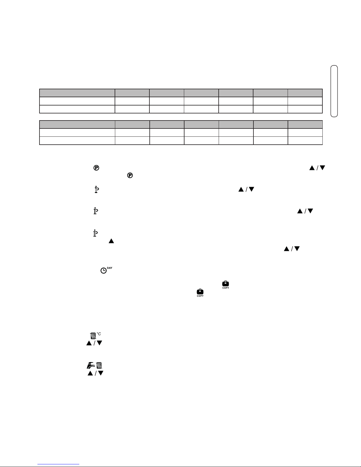
The preset automatic programme is:
MONDAY - FRIDAY BAND 1 BAND 2 BAND 3 BAND 4 BAND 5 BAND 6
START TIME 6:30 8:00 12:00 14:00 18:00 22:30
TEMPERATURE LEVEL 21°C 18°C 21°C 18°C 21°C 16°C
SATURDAY - SUNDAY BAND 1 BAND 2 BAND 3 BAND 4 BAND 5 BAND 6
START TIME 8:00 10:00 12:00 14:00 18:00 22:30
TEMPERATURE LEVEL 21°C 21°C 21°C 18°C 21°C 16°C
Follow the instructions given below to modify the preset automatic programme.
1. Press the button . If DHW programming is enabled, select the radiator symbol with the buttons
and conrm with thew button and numebre 1 of DAY 1 is show down in a box to indicate
that time band 1 of Monday can be modied
2. Press the button . The hours and minutes start ashing: use button to change the
time band start time in 10 minutes increments. By keeping the button presses the hours will change
rapidly.
3. Press the button . The room temperature inside the house starts ashing: use the buttons
to change the temperature level in 0.1 °C increments. By keeping the button pressed the temperature
will change rapidly.
4. Press the button . The 6 daily time bands ash
5. Then press the button to disply time band 2 of Monday, modiable by repeating step 2 to 4.,
6. The remaining time bands can be displayed by selecting bands 3, 4, 5 or 6 with buttons and
repeating step 5
7. The programme setting for the following day can now be selected:
a. Press the button to display time band DAY 2. The Thuesday programme can be modied
by repeating steps 2 to 6.
b. To copy the Monday programme to Tuesday, press the button . To copy the same programme
also to the other days of the week, press the button repeatedly.
Important! When setting the programme make sure each band has a dierent start time.
Heating - Domestic Hot Water Temperature Adjustment
Heating
Press the button : the display shows the current heating circuit water temperature setting, adjustable
using the buttons in 1°C increments. Press any button to exit the menu.
DHW
Press the button : the display shows the current domestic hot water temperature setting, adjustable
using the buttons in 1°C increments (only if function is enabled). Press any button to exit the menu.
Page 10

10
Holiday Function
The Holiday Function is used to switch o heating (also domestic hot water production for boilers with a
storage tank) for a given period of time, from 1 hour to 45 days, adjustable in 1 hour increments. This makes
it possible to save energy when away from home, whereas the previously set operation mode resumes
as soon as the Holiday function ends. Heating is activated only if the room temperature falls below 5°C:
freezing protection function.
Follow the instructions given below to activate and set the Holiday function.
1. Press the button . The symbol starts ashing and the hours minutes became -00:01, which is
the time remaining before the end of the Holiday function
2. Use the buttons to extend the time remaining until the end of the Holiday function in 1 hour
increments (-00:01 means 1 hour; -45:00 means 45 days). By keeping the button pressed the
time and days will change rapidly.
3. During the Holiday function the display will continue to show the time remaining until the end of the
function.
To cancel the Holiday function press the button or any other button associated with a dierent operation
mode.
Telephone contact input (GSM)
Normal Remote Control operation is ensured as long as the telephone contact remains open. The closing
of this contact, indicated on the display with the symbols ( ), can be used to force the Remote Control to
switch o heating or to set the room temperature to a preset xed value.
Follow the instructions given below to activate and set the two functions.
1. Keep the button pressed for 3 seconds.
2. The display shows the CU parameter.
3. Press the button 9 times.
4. The display shows parameter P8.
Set to 0 using the buttons to switch o heating when the contact is closed.
Set to 1 using buttons means of parameter P9) when the contact is closed.
ad un valore sso preimpostato (attraverso il successivo parametro P9) alla chiusura del contatto.
5. Press the button .
6. The display shows parameter P9
Set the room temperature value that the Remote Control will adjust when the contact is closed
(if parameter P8 is set to 1) by pressing the buttons in 0.1°C increments. By keeping the
button pressed the temperature will change rapidly.
7. Press any other button to exit the menu.
Modication of the Remote Control operating mode on opening or closing of telephone conctact can occur
in a maximum time of 120 seconds.
Page 11

11
ENGLISH
User parameter Editing
Sliding Temperature - Compensation Curve
By installing the external probe (optional), the control system can work with a Sliding Temperature. The
external probe must be connected to the boiler card: refer to the relevant handbook for details. In this mode,
the heating system temperature is adjusted according to the outside weather conditions in order to ensure
high comfort and energy saving throughout the year. In particular, as the external temperature increases
the system delivery temperature decreases according to a specic compensation curve. With the Sliding
Temperature adjustment the temperature set through the “Heating temperature adjustment” setting becomes the maximum system delivery temperature. It is advisable to set a maximum value to allow system
adjustment throughout its useful operating range.
The compensation curve can be set from 1 to 10
according to the following graph.
1. Keep the button pressed for 3 seconds
2. The display shows the CU parameter.
Press the buttons to modify the compen sation curve by increments of 1 unit. By
keeping the button pressed the value will
change rapidly.
3. Press any other button to exit the menu
Set the compensation curve to 0 to disable Sliding
Temperature adjustment.
Sliding Temperature - Paralell Curve Oset
Once the Compensation curve has been set, parallel curve oset can be adjusted from 20 to 40 as shown
in the following graphs:
The system must be adjusted at the time of installation by qualied personnel. Possible adjustments can in
any case be made by the user to improve comfort. If the room temperature is lower than the required value,
it is advisable to set a higher order curve and vice versa. Proceed by increasing or decreasing in steps of
one and check the result in the room
1. Keep the button for 3 seconds.
2. The display shows the CU parameter.
3. Press the button .
4. The display shows the OF parameter.
Press the buttons to modify parallel
curve oset in 1°C increments. By keeping
the button pressed the value will change rapidly
5. Press any other button to exit the menu.
Page 12

12
Enable DHW programming
Follow the instructions given below to enable domestic hot water programming.
1. Keep the button pressed for 3 seconds.
2. The display shows the CU parameter.
3. Press the button twice.
4. The display shows parameter P1.
Set to 0 using the buttons to disable domestic hot water programming. Set to 1 using the
buttons to enable domestic hot water programming.
5. Press any other button to exit the menu.
To set the weekly automatic programme proceed as described in the section “Step 2. Automatic weekly
programme setting”, selecting the tap symbol at step “1” and setting EC (Economy) or CO (Comfort) at step
“3” rather than a temperature value. In fact the remote control has a weekly time programmer based on two
levels: during the COMFORT level, the boiler will maintain the set hot water tank temperature; during the
ECO level, the boiler will not deliver domestic hot water. Refer to the boiler documentation for information
on the type of hot water storage tank.
Important: Make sure the remote control is set to Winter mode with automatic operation
Pre-heating Function
This function is active only if the automatic heating mode has been selected. When set to Automatic, the
function anticipates the heating system start time (not before 00:00 hours on the same day) so that the
room temperature set by the user is reached at the start of the programmed time band. The Remote Control
calculates an initial hypothetical Pre-activation time: if the programmed room temperature is reached in a
shorter time than that calculated, the Pre-Heating time will be decreased, and vice versa. This creates a
self-learning process, for identifying the minimum necessary Pre-activation time.
The Remote control also oers also the possibility of setting a xed Pre-Heating slope: In this case, the
room temperature will be increase by 3°C an hour. Therefore the automatic heating programme should
be set according to the time when heat is required and not that when the heating system is to be started.
Follow the instructions given below to activate or deactivate this function.
1. Keep the button pressed for 3 seconds
2. The display shows the CU parameter.
3. Press the button 3 times.
4. The display shows parameter P2.
Set to 0 using the buttons to deactivate Pre-Heating.
Set to 1 using the buttons to activate Automatic Pre-Heating
Set to 2 using the buttons to activate Pre-Heating. Set to 2 using the butons to activate
the Pre-Heating function with a xed slope of 3°C per hours.
5. Press any other button to exit the menu.
During the preheating function the room temperature °C symbols ashes
The pre-heating function ends when the dierence between the programmed room temperature and the
actual room temperature is less than 0.5 °C.
Page 13

13
ENGLISH
Maximum number of daily time bands
The heating programme provides for 6 daily time bands for temperature levels, numbered from 1 to 6. If
necessary, the time bands can be reduced to a minimum of two.
1. Keep the button pressed for 3 seconds.
2. The display shows the CU parameter..
3. Press the button 4 times.
4. The display shows parameter P3.
Use the buttons to modify the number of daily time bands from 2 to 6.
5. Press any other button to exit the menu.
Heating minimum temperature
Follow the instructions given below to set the minimum heating circuit water temperature in 1°C steps.
1. Keep the button pressed for 3 seconds.
2. The display shows the CU parameter.
3. Press the button 5 times.
4. The display shows parameter P4.
Use the buttons to adjust the parameter in 1°C increments. By keeping the button pressed the
value will change rapidly.
5. Press any other button to exit the menu.
System lling
This function manages the operation mode of the electric device for lling the water circuit in a certain
model boiler
1. Keep the button pressed for 3 seconds.
2. The display shows the CU parameter.
3. Press the button 6 times.
4. The display shows parameter P5.
Set to 0 using the buttons to deactivate the electric lling device. Set to 1 using the buttons
to activate Automatic system lling
5. Press any other button to exit the menù.
Important:
Set the boiler control card to manual lling. In manual mode, if the sensor installed in the boiler detected
insucent pressure, the bar icon will ash on the display: press the Reset button to activate the special
solenoid valve. During manual or automatic. Once the nominal pressure is restored, the remote control will
return to the normal display.
Temperature Unit of measure selection
Follow the instructions given below to use the Remote Control in °C or in °F.
1. Keep the button pressed for 3 seconds.
2. The display shows the CU parameter.
3. Press the button 7 times.
4. The display shows parameter P6.
Set to 0 using the buttons to select °C. Set to 1 using the buttons to select °F
5. Press any other button to exit the menu
Room temperature reading corerction
Follow the instructions given below to correct the room temperature reading between -2°C and +2°C in
0.1°C steps.
1. Keep the button pressed for 3 seconds.
2. The display shows the CU parameter.
3. Press the button 8 times.
4. The display shows parameter P7
Set to 0 using the buttons to adjust the parameter in 0.1°C increments.
5. Press any other button to exit the menu
Page 14

14
Other function
Information menu
The remote control can provide the user with information on boiler status. Each press of the button allows
the cyclic display of the following information:
T1 - Heating circuit delivery water temperature
T2 - Domestic hot water temperature
T3 - Heating circuit return water temperature (boilers with sensor only)
T4 - Delivery water temperature setpoint calculated by the remote control
P5 - Actual burner power
F6 - Actual fan speed (condensing boilers only)
F7 - Actual DHW owrate (instant hot water boilers with owmeter only)
P8 - Actual system pressure (boilers with pressure sensor only)
v - Remote control software version
Press any other button to exit the menu.
Power Failure
In this case the Bridge RF stops working, because it is electrically fed by the boiler card. The symbol ( )
shown on the Remote Control display starts ashing. If the power is restored within 2 minutes, the symbol
becomes xed again and RF communication is immediately activated. Otherwise the display activates
fault E94 and the symbol : once the power is restored, it is necessary to wait 15 minutes. After which
the symbol becames xed and RF communication is avaible again.
Diagnostic
The remote control constantly monitors boiler staus and signals any faults by activating an alarm icon and
specic fault code: for a description of the fault, refer to the boiler documentation. Certain faults cause permanent shutdowns (indicated with the letter “A”): to reinstate operation just press the RESET button; other
faults (indicated with the letter “F”) cause temporary shutdowns which are automatically reset as soon as
the value returns within the boiler’s normal working range.
Room temperature probe fault
In case of a Remote Control room temperature probe, the display activates fault code E92 and the
symbol . Heating is switched o.
External temperature probe fault
In Sliding Temperature operation and in case of an external temperature probe (optional) fault, the display
activates fault code E93 and the symbol . The adjustment temperature become xed at the ‘‘Heating
temperature adjustment’’ value. To eliminate the fault, reset the external probe or disable Sliding Temperature adjustment.
Page 15

15
ENGLISH
Page 16

Unical declines every responsibility for the possible inaccuracies if owed to errors of transcript or press.
Also reserves the right to bring those changes that it will hold necessary to it own products or prots, without jeopardizing its essential characteristics.
46033 casteldario - mantova - italia - tel. +39 0376 57001 - fax +39 0376 660556
info@unical-ag.com - export@unical-ag.com - www.unical.eu
AG S.p.A.
00337153 - 1
a
ed. 04/17
www.unical.eu
 Loading...