


DUA plus
BTN 28 - BTFS 28
00333957 - 1st edition - 09/2011
INSTALLATION AND USER
INSTRUCTION MANUAL

2
General info
While thanking you for buying an UNICAL product we invite you to carefully read the following forewarnings:
IMPORTANT
This INSTRUCTION MANUAL, which is an integral and indispensable part of the product, must be handed over to the user by
the plumber.
Read carefully the forewarnings contained in this manual because they supply important indications concerning the
safetywhen using and maintaining the boiler. Kept the manual in a safe place for any future reference.
The boiler must be installed by qualified personnel, in compliance with all applicable laws and standards, according to the
manufacturer’s instructions given in this manual.
Incorrect installation may cause injury to persons and/or animals and damage to property. The manufacturer shall not be held
liable for any such injury and/or damage.
After removal of the packaging, which has to be sent to specific waste management sites for recycling, check that the boiler is intact and
that it has not been damaged during transport and handling. Keep the packaging out of the reach of children as it may represent a choking
and suffocation hazard. Do not install equipment which is patently damaged and/or faulty.
Before installing the boiler, check that the technical data supplied by Unical, correspond to requirements for its correct use in the system.
Before making any service on to the boiler switch off the power supply.
In the event of failure and/or faulty functioning, switch off the boiler. Do not attempt to make repairs: contact qualified technicians.
Original parts must be used for all repairs to the boiler.
Non-observance of the above requirement may jeopardize the safety of the boiler and expose people, animals and proper ty to danger.
To grant the efficiency of the appliance and for its proper operation it is necessary to do a periodical service according to the
UNICAL's indications and local laws in force.
The manual must be handed over with the boiler should it be sold or transferred, in order that the new owner and/or installer can consult it.
Only original accessories must be used for all boilers supplied with optional kits (including electrical ones).
This boiler must be used for the purposes for which it has been designed. Any other use shall be considered incorrect and therefore
dangerous.
Damage and/or injury caused by incorrect installation or use and/or damage and/or injury due to non-observance of the manufacturer’s
instructions shall relieve UNICAL from any and all contractual and extracontractual liability.
To guarantee efficiency and correct functioning of the equipment it is legally binding to service the boiler once a year according to the
schedule indicated in the relative section of this manual.
In the event of long periods of inactivity of the boiler, disconnect it from the power mains and close the gas tap (Warning! In this case the
boiler’s electronic anti-freeze function will not be operative).
Should there be a risk of freezing, add anti-freeze: it is not advisable to empty the system as this may result in damage; use specific antifreeze products suitable for multi-metal heating systems.
N.B.: IF YOU SMELL GAS:
- do not turn on or off electrical switches and do not turn on electrical appliances;
- do not ignite flames and do not smoke;
- close the main gas tap;
- open doors and windows;
- contact a Service Centre, qualified installer or the gas supply company.
Never use flames to detect gas leaks.
WARNING
This boiler has been built for installation in the country indicated on the technical data plate, which shows, in addition to the technical
features, also the gas type for which it is prepared to work. In case these indications do not correspond to your requirements, please
contact your nearest Unical supplier. Thanks for that.
"WATER TREATMENT IN C.H. SYSTEM FOR CIVIL USE"
NOTE FOR INSTALLER AND USER
1) The frequency of the cleaning of the D.H.W. heat exchanger is related to the hardness of the feeding water.
2) With a water hardness higher than 14°f the use of antiscaling devices, whose choice will be made on the base of water characteristics,
is suggested.
3) To increase the resistance to the scaling, a D.H.W. temperature adjustment very close to that one of the actual use, is suggested.
4) The adoption of a modulating room thermostat reduces the scaling danger.
5) We advise you to verify the state of cleaness of the D.H.W. heat exchanger at the end of the first year and subsequently every two
years.
PED Declaration
The appliance DUA plus BTN 28 e DUA plus BTFS 28
is not under the scope of the PED Directive 97/23/CE, because it belongs to a category lower than the 1st, on the base of the comparation
of their features with the limits shown on the table 4 of the directive. Furthermore the appliance is already covered by the Directives 90/396/
CE (GAD - Gas Appliances Directive) and 73/23/CEE (LVD - Low Tension Directive)
3
General info
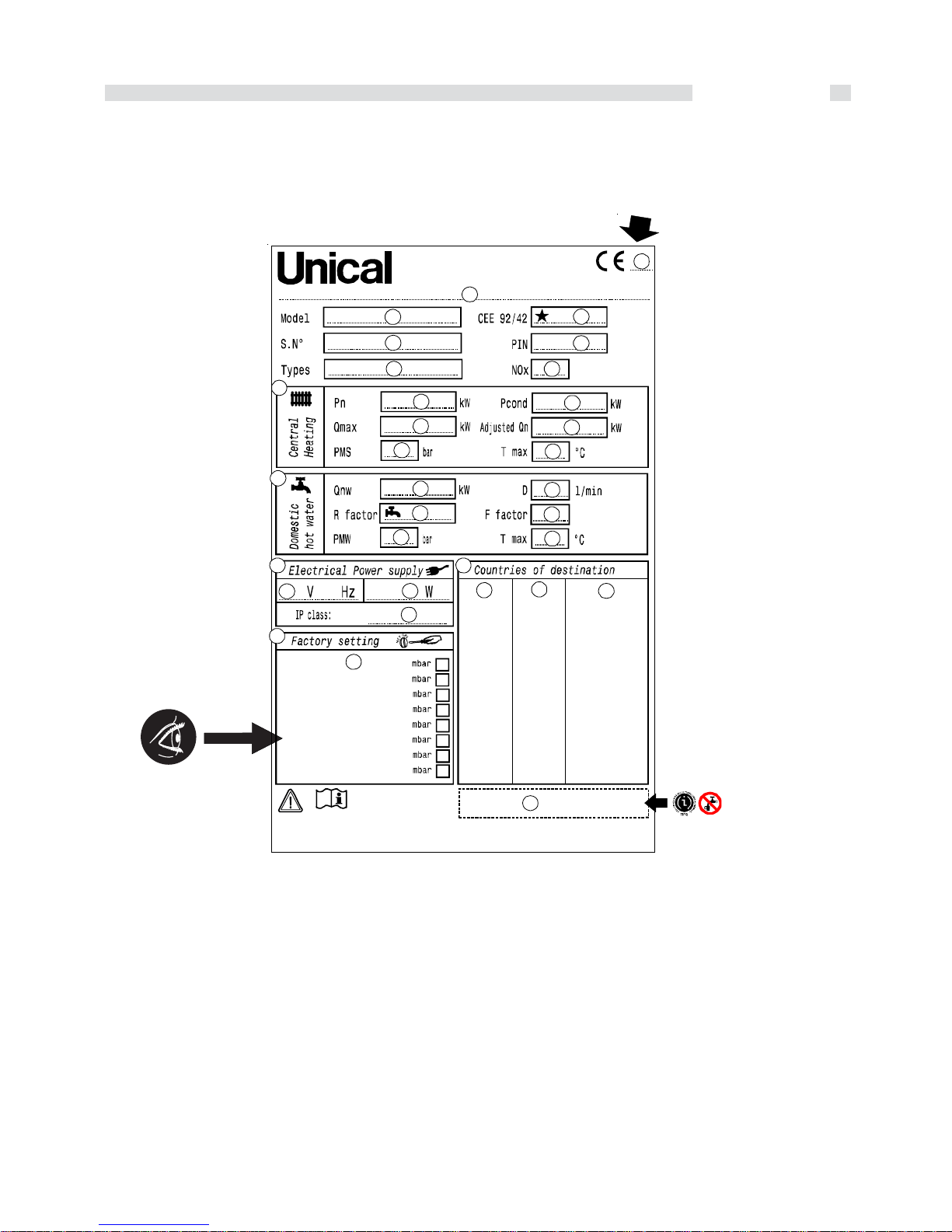
DATA PLATE DESCRIPTION
LEGEND:
1 = CE Surveillance notify body
2=Boiler type
3=Boiler model
4=Number of stars (Directive 92/42/CEE)
5=(S.N°) Serial number
6=P.I.N. code
7=Approved fluing configurations
8=(N0x) N0x class
A Central Heating circuit features
9=(Pn) Nominal output
10 = (Pcond) Condensing nominal output
11 = (Qmax) Nominal heat input
12 = (Adjusted Qn) Adjusted for nominal Heat input
13 = (PMS) Max. pressure C.H. system
14 = (T max) Max. C.H. temperature
B Domestic Hot Water circuit features
15 = (Qnw) Nominal heat input in D.H.W. mode (if different from Qn)
16 = (D) Specific D.H.W. flow rate according to EN 625-EN 13203-1
17 = (R factor) N° taps based on the quantity of water declared EN
13203-1
18 = (F factor) N°stars based on the quality of water declared
EN 13203-1
19 = (PMW) Max. pressure D.H.W. system
20 = (T max) Max. temperature D.H.W system
C Electrical features
21 = Electrical power supply
22 = Consumption
23 = Protection grade
D Countries of destination
24 = Direct and indirect country of destination
25 = Gas family
26 = Supply pressure
E Factory setting
27 = Adjusted for gas type X
28 = Space for national brands
CE Marking
- The CE marking documents that the boilers satisfy:
- The essential requirements of the Directive regarding gas
appliances (Directive 90/396/CEE)
- The essential requirements of the Directive regarding
electromagnetic compatibility (Directive 89/336/CEE)
- The essential requirements of the Efficiency Directive (Directive
92/42/CEE)
- The essential requirements of the low voltage Directive (Directive
73/23/CEE)
®
1
2
3
5
7 8
6
4
9
11
13
10
12
14
15
17
19
16
18
20
28
A
B
21 22
23
24
25
26
27
C D
E

4
General info
TECHNICAL CHARACTERISTICS AND
DIMENSIONS....................................................................... pag. 5
1.1 Technical characteristics ...................................................... pag. 5
1.2 Dimensions ............................................................................. pag. 5
1.3 Hydraulic circuits ................................................................... pag. 6
1.4 Operational data ..................................................................... pag. 8
1.5 General specifications ........................................................... pag. 8
INSTRUCTIONS FOR
THE INSTALLER .............................................................. pag. 9
2.1 Installations conditions .......................................................... pag. 9
2.2 Installation ............................................................................... pag. 9
2.2.1 Packaging .................................................................. pag. 9
2.2.2 Position of the boiler .................................................. pag. 10
2.2.3 Assembly the boiler ................................................... pag. 10
2.2.4 Ventilation ................................................................... pag. 11
2.2.5 Smoke evacuation systems ..................................... pag. 11
2.2.6 Smoke discharge system forced draught boilers ... pag. 14
2.2.7 Smoke discharge system forced draught boilers ... pag. 15
2.2.8 Smoke discharge with separate ducs Ø80 mm ...... pag. 16
2.2.9 On site combustion efficiency measurement .......... pag. 18
2.2.10 Gas supply line ......................................................... pag. 18
2.2.11 Hydraulic connections .............................................. pag. 18
2.2.12 Electrical connections ............................................... pag. 19
2.3 Electrical wirings .................................................................... pag. 20
2.3.1 Actual connection diagram ....................................... pag. 20
2.3.2 Jumper position ......................................................... pag. 22
2.4 Filling of the heating system .................................................. pag. 23
2.5 Burner adjustment.................................................................. pag. 23
2.6 Burner adjustment.................................................................. pag. 24
2.7 Adaptation to the use of other gas ........................................ pag. 26
2.8 Fault finding and reparation ................................................... pag. 27
INSTRUCTIONS FOR THE USER ...................... pag. 28
3.1 Panel board ............................................................................ pag. 28
3.2 Ignition and extinction ............................................................ pag. 30
3.3 Notes....................................................................................... pag. 30
1
2
3
For your own safety, observe these safety instructions.:
PLEASE NOTE:
User tip for the optimum utilisation
and setting of the control(s) plus
useful information.
WARNING
from risk of electric shock.
WARNING
Identifies potentially dangerous
situations.

Technical features and dimensions
5
1
- EMC Directive 89/336/EEC dated 3 May
1989 amended by Directive 92/31/EEC
dated 28 April 1992;
- European Community’s Low Voltage
Directive 73/23/EEC dated 19 February
1973 amended by Directive 93/68/EEC
dated 22 July 1993;
The main technical features of the DUA
plus B boilers are summarised below:
· 60 litre enamelled upright storage tank
with a helical steel heat exchanger;
· Monothermal, copper, high performance
heat exchanger;
· Adjustment of maximum output in heating
mode;
· Adjustment of the flame modulation as a
function of the absorbed power;
· NTC sensor for D.H.W. priority;
· Safety pressure switch for low water
level;
· System water inlet tap;
· Storage tank exhaust tap;
· Circulation pump with automatic air vent;
· Filling tank pump with automatic air vent;
· High limit thermostat (105°C);
· Anti-freeze protection;
· 7,5 litre expansion vessel;
· 4 litre sanitary expansion vessel
(optional);
· Automatic differential by-pass;
· Control panel with IP X4D insulation
protection;
· Led indication of: D.H.W. demand, C.H.
demand, voltage presence, burner in
operation, temperature scale, faults,
chimney sweeper mode;
· Manometer;
· Tap water flow rate restrictor set at 12
litres/min;
· Unlocking of check valves;
· C.H. temperature selector (35 - 85°C);
· D.H.W. temperature selector (35 - 65°C);
· Main selector Winter / Summer /
Antifreeze / Only Heating;
· Minimum outer temperature calibration (if
an outer sensor is connected);
· Mounting frame with valves for easy
hydraulic connections (optional);
· Electronic ignition with double electrode;
· Casing painted with epoxypoliester
pouders;
· Flue gas antispillage thermostat (natural
draught open chamber version);
· Heating exhaust tap.
1.1- TECHNICAL
FEATURES
DUA plus is a wall hung gas boiler with
built-in atmospheric gas burner for heating
and D.H.W. production; it is available in the
following versions:
DUA plus BTN 28 with natural draught
open chamber
DUA plus BTFS 28 with forced draught
room sealed
combustion
chamber
All versions have electronic ignition.
DUA plus B boilers are supplied with all
control and safety features according to the
latest laws in force, and comply with the
fundamental requirements of the following
EEC directives:
The BEA boilers comply with the
fundamental
requirements of the following EEC
directives:
- Directive Gas 90/396/EEC dated 29 June
1990;
- Yield Directive 92/42 EEC dated 21 May
1992;
fig. 1
182
167
600
870
475
®
plus
DUA
R
F
M
G
140
42
175
69 189
65
71,5
57 148,5
C
1.2 - DIMENSIONS
TECHNICAL FEATURES ET DIMENSIONS
view from above
view from below
Technical features and dimensions
6
fig. 2
fig. 3
DUA plus BTN 28
DUA plus BTFS 28
MRGCF
13
12
9
8
7
6
5
4
3
2
1
10
11
14
20
26
19
18
17
16
21
22
23
24
25
27
28
29
RGMCF
5
4
3
2
1
6
7
9
10
16
15
14
13
12
11
19
18
17
20
21
23
22
24
29
25
26
27
28
30
31
32
33
34
8
15
30
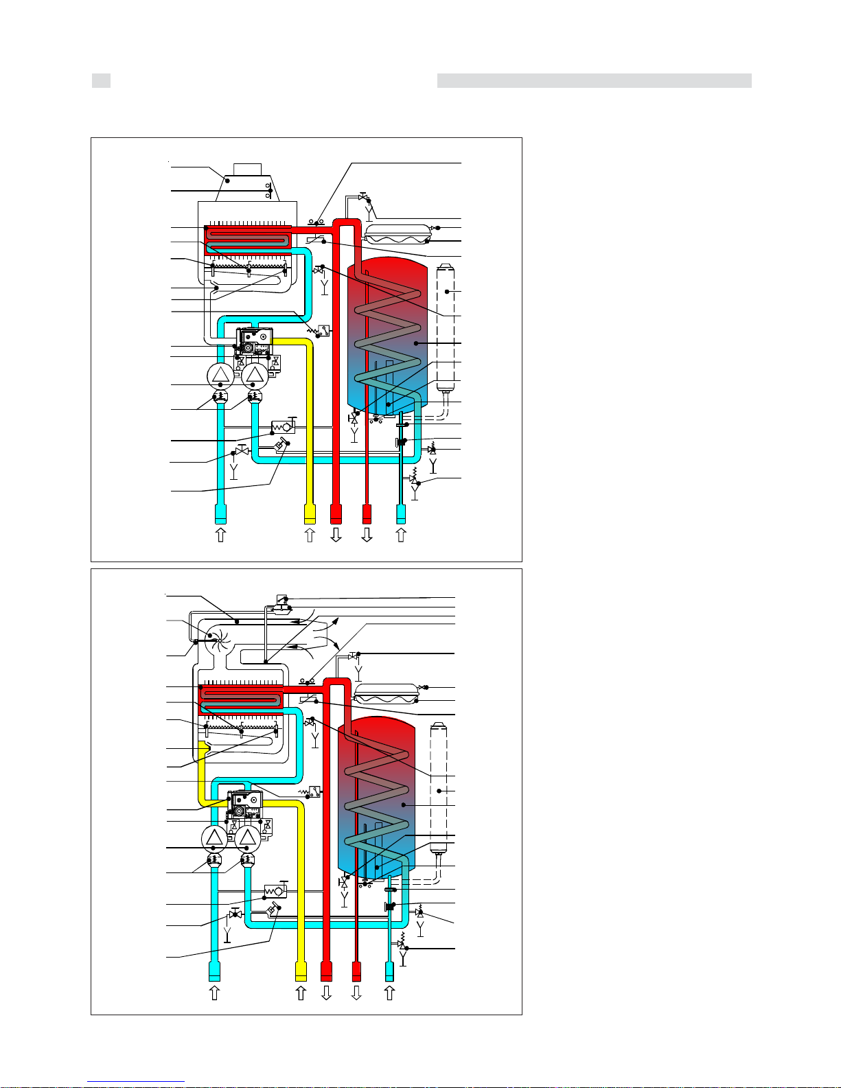
1.3 - HYDRAULIC CIRCUITS
1 Filling system cock
2 Boiler draining valve
3 By-pass
4 No-return valve
5 Pump
6 Air vent
7 Modulating gas valve
8 Low water pressure switch
9 Ignition electrode
10 Burner injectors
11 Ignition electrode
12 Ionisation electrode
13 Main heat exchanger
14 Smoke safety thermostat
15 Draught diverter
16 Safety thermostat
17 Manual air vent
18 Boiler expansion tank valve inflation
19 Expansion vessel
20 Flow temperature sensor
21 Expansion vessel l. 4 (optional)
22 Heat exchanger draining valve
23 Tank
24 Tank draining valve
25 Magnesium anode
26 Tank temperature sensor
27 Domestic Hot Water flow restrictor
28 Filter
29 C.H. safety valve
30 Boiler safety valve
M C.H. flow 3/4"
C D.H.W. outlet 1/2"
G Gas inlet 3/4"
F D.C.W. inlet 1/2"
R C.H. return 3/4"
1 Filling system cock
2 Boiler draining valve
3 By-pass
4 No-return valve
5 Pump
6 Air vent
7 Modulating gas valve
8 Low water pressure switch
9 Ignition electrode
10 Burner injectors
11 Ignition electrode
12 Ionisation electrode
13 Main heat exchanger
14 Smoke pressure nipple
15 Extraction fan
16 Air intake and smoke evacuation duct
17 Microswitch of the smoke pressure
18 Safety pressureswitch of smoke circuit
19 Smoke pressure nipple
20 Safety thermostat
21 Manual air vent
22 Boiler expansion tank valve inflation
23 Expansion vessel
24 Flow temperature sensor
25 Heat exchanger draining valve
26 Expansion vessel l. 4 (optional)
27 Tank
28 Tank draining valve
29 Magnesium anode
30 Tank temperature sensor
31 Domestic Hot Water flow restrictor
32 Filter
33 C.H. safety valve
34 Boiler safety valve
M C.H. flow 3/4"
C D.H.W. outlet 1/2"
G Gas inlet 3/4"
F D.C.W. inlet 1/2"
R C.H. return 3/4"

Technical features and dimensions
7
DUA plus BTN 28
II2H3+
8,9
0,5
3
3,25
85
35
7,5
139,9
0,5
6
60
16
12
8,98
9,98
11,43
13,33
15,99
187
35 - 65
230/50
4
89
X4D
82
l/min
bar
bar
l
°C
°C
l
l
bar
bar
l
l/min.
l/min.
l/min.
l/min.
l/min.
l/min.
l/min.
l
°C
V-Hz
A (F)
W
IP
kg
kW
kW
%
%
%
%
n.
%
%
%
°C
g/s
%
%
mg/kwh
%
%
DUA plus BTN 28
27,9
12,5
89,95
89,89
89,68
87,34
2
92,87
88,88
2,62 - 2,92
64,6 - 83,4
22,05 - 24,3
126,46
2,3 - 4,6
186
2
11,12 - 7,13
0,449
DUA plus BTFS 28
28,8
12,9
92,94
92,92
92,04
90,38
3
94,96
90,74
2,04 - 2,02
60,4 - 69,6
19,51 - 20,55
89,4
2,6 - 5,9
-
-
130
3
11,03 - 6,61
0,489
DUA plus BTFS 28
II2H3+
8,8
0,5
3
3,25
85
35
7,5
139,3
0,5
6
60
16
12
9,1
10,2
11,7
13,6
16,4
187
35 - 65
230/50
4
148,5
X4D
89
1.4 - OPERATIONAL DATA
For some data (NOZZLES - BURNER GAS PRESSURE - DIAPHRAGMS - INPUTS - GAS CONSUMPTIONS)
refer to paragraph ADAPTATION TO THE USE OF OTHER GAS on page 26.
1.5 - GENERAL SPECIFICATIONS
(*) Warning: The utilisation of this type of boilers in the "floor heating systems" needs the use of specific equipments (e.g.:
UNICAL Thermic Module) to avoid all risks of smoke condensation within the boiler.
Nominal output
Minimum output
Actual water efficiency at 100 % of nominal load
Minimum water efficiency required at 100 % of nominal load
Actual water efficiency at 30 % of nominal load
Minimum water efficiency required at 30 % of nominal load
Star number (according to Efficiency Directive 92/42/CE)
Combustion efficiency at 100 % of nominal load
Combustion efficiency at minimum load
Heat losses through the casing (min. / max.)
Maximum net smoke température (Ts- Ta)
Massive smoke flow rate (min. / max.)
Air exces (lambda)
CO
2
NOx (ponderal value according to EN 297/A3+EN 483)
NOx class (ponderal value according to EN 297/A3 + EN 483)
Chimney heat losses with burner in operation (min./max.)
Chimney heat losses with burner shut-off
Boiler category
Minimum water low rate in heating circuit (ΔT 20°C)
Minimum pressure in heating circuit
Maximum pressure in heating circuit
Water content of the primary circuit
Maximum operation temperature in heating mode
Minimum operation temperature in heating mode (*)
Expansion vessel total content
Maximum water content of the heating circuit (max. temp. 90°C)
Minimum pressure in the D.H.W. circuit
Maximum pressure in the D.H.W. circuit
Tank capacity
Specific D.H.W. flow rate ( t 30°C according to EN 625)
Flow rate of the D.H.W. flow restrictor
Contiunuous D.H.W. production with t 45 K
Contiunuous D.H.W. production with t 40 K
Contiunuous D.H.W. production with t 35 K
Contiunuous D.H.W. production with t 30 K
Contiunuous D.H.W. production with t 25 K
DHW available at a temp. of 45°C in the first 10 mins of draw-off with storage
tank water at 60°C and cold water at 10°C (*)
D.H.W. temperature adjustable between
Electrical power supply Tension/Frequency
Supply fuse
Maximum absorbed output
Insulation degree
Net weight (dry)

Installation info
8
fig. 4
650
960
665
2
INSTRUCTIONS FOR
THE INSTALLER
2.1 - INSTALLATION
CONDITIONS
DUA plus is a gas boiler which must be
installed in accordance with the latest
regulations or rules in force.
For the boiler category, which changes
according to the destination country,
see page 3.
NOTE:
Observe the corresponding technical rules
and the building supervisory and statutory
regulations of the country of final use
when installing and operating the system.
Always ensure that an appropriately
specialised company is entrusted with
installation, gas supply and flue gas
connection, commissioning and power
supply, as well as all servicing and repair
works.
Work on gas conduits and fittings must only
be carried out by a registered service
provider.
The system must be cleaned and serviced
once a year. This includes an inspection of
the entire system to see if it is in full
working order.
Defects and faults must be eliminated
immediately.
Please note that we can accept no liability
whatsoever for loss or injury resulting from
unauthorised adjustment or manipulation of
the system’s control or regulating devices.
2.2 - INSTALLATION
2.2.1 - PACKING
Dua plus B is packed and delivered in a
strong cardboard box. Once the boiler has
been unpacked check that it is intact. The
packaging material can be recycled and it
must be disposed of accordingly.
Keep the packaging out of the reach of children as it represents a choking and suffocation hazard.
UNICAL waives all liability for injury to
persons and animals or damage to property resulting from non-observance of
the above.
The packaging contains:
- the copper pipe kit for hydraulic connec-
tion of the boiler to the heating and water
system and to the gas mains;
- a bag with:
a) installation, use and maintenance hand-
book,
b) template for fixing the boiler to the wall,
c) 4 screws with dowels to fix the boiler to
the wall,
d) for models TFS, a diaphragm for flue gas
exhaust.

Installation info
9
fig. 5
2.2.3 - ASSEMBLING THE BOILER
Before connecting the boiler to the D.H.W.
and heating system pipes, carefully clean
the pipes to remove all traces of metal
resulting from processing and welding
operations as well as any oil and grease
which could damage the boiler or
jeopardize its operation.
Unical refuses all liability for injury to persons
and animals or damage to property resulting
from non-observance of the above.To install
the boiler:
- Fix with tape the paper template to the
wall
- make two Ø 12 holes in the wall and
insert the hooks;
- position the junction points for the
connection of the gas supply pipe, cold
water supply pipe, D.H.W. outlet, CH flow
and return in the positions shown by the
template.
- fit the boiler onto the support hooks;
- connect the boiler to the gas pipe,
domestic cold and hot water pipes, CH
flow and return pipes.
- connect to electrical supply.
NOTE:NOTE:
NOTE:NOTE:
NOTE:
--
--
-
Do not use solvents which couldDo not use solvents which could
Do not use solvents which couldDo not use solvents which could
Do not use solvents which could
damage the components.damage the components.
damage the components.damage the components.
damage the components.
M = C.H. flow 3/4"
C = D.H.W. outlet 1/2"
G = Gas inlet 3/4"
F = D.C.W. inlet 1/2"
R = C.H. return 3/4"
S = Draining safety valve
MOUNTING TEMPLATE
2.2.2 - POSITIONING OF THE BOILER
Every boiler is supplied with a dedicated
"Metallic mounting jig" to allow the correct
positioning of the gas, water and C.H.
system connections when the hydraulic
system is being laid out and before the boiler
is installed.
This mounting jig must be fixed to the wall
chosen for the installation of the boiler using
two screws with expanding dowels.
The lower part of the mounting jig allows the
correct marking on the wall of the points
where the fittings for the gas, C.H. flow and
return, D.H.W. and D.C.W. have to arrive.
Determine the position of the boiler taking
care:
- of leaving a minimum clearance of 50
mm on both sides of the boiler to allow
accessibility for service.
- of a good resistance of the screws
supporting the boiler on the wall.
- of avoiding to position the boiler above
an equipment whose use could be
prejudicial for the boiler (stove with
emission of greasy vapours, washing
machines, etc...).
IMPORTANT:
350 mm free space must be left between
the top of the boiler and the ceiling to
allow replacement of the magnesium
anode. This condition is met when there
is a space of 436 mm between the axis of
the holes in the boiler bracket and the
ceiling.
The mounting jig allows the completion of all
the connections and the making of the
soundness test of the full installation without
the boiler in place.
If the boiler is not put in place immediately,
protect the different connections in order to
avoid that the mortar and the paint
cannot compromise the soundness of the
subsequent connections.
Because the temperature of the wall, on
which the boiler is fitted, does not rise more
than 60 K when the boiler is in operation,
there are no special requirements to comply
with.

Installation info
10
2.2.4 - VENTILATION
The boiler must be installed in a suitable room
according to the rules in force and particularly:
NATURAL DRAUGHT OPEN FLUE BOILERS
(TYPE B11bs and VMC INSTALLATIONS)
The boilers DUA PLUS TN, are open flue
boilers and are foreseen for chimney
connection: the air for combustion is taken
directly from the room in which the boiler is
installed.
The room can have both a direct ventilation
(i.e. with ventilation openings facing outwards) or an indirect ventilation (i.e. with ventilation openings facing an adjacent room)
provided that the following requirements are
complied with:
Direct ventilation:
- The room has to have a ventilation opening of, at least,
6 cm² /kW of installed input (see input
table on par. 2.7) and, in no case, lower
than 100 cm² and made directly onto an
external wall.
- The opening has to be as close as possible to the floor.
- It should not be possible to close it and it
should be protected with a grate not reducing its usefull ventilation section.
- A correct ventilation can be optained also
through the addition of more openings,
provided the addition of the different sections is not less than that really needed.
- In case it is not possible to make a ventilation opening close to the floor, it will be
necessary to increase its usefull section
of at least 50%.
- If an open fire is present in the same room
it needs an indipendent air supply, otherwise the installation of a type B appliance
is not permitted.
- If in the room there are other devices
which need air for their operation (e.g. a
wall exhauster) the section of the ventilation opening has to be the properly sized.
Indirect ventilation
In case it is not possible to make a room
ventilation opening on an external wall, it is
possible to have an indirect ventilation,
sucting the air from an adjacent room,
making an
opening in the lowest part of a door.
This solution is possible only if:
- The adjacent room is not a bed room
- The adjacent room is not a common part
of the building and is not a room with fire
danger (e.g. a fuel deposit, a garage, etc..)
FORCED DRAUGHT ROOM SEALED BOILER
(TYPE C12 - C32 - C42 - C52 - C62 - C82)
The DUA PLUS TFS are forced draught,
room seal-ed boilers; so they do not need
particular ventilation openings for the
combustion air, in the room in which they
are installed.
FORCED DRAUGHT, OPEN FLUE
BOILER
(TYPE B22)
If the DUA PLUS TFS are installed in a room
ac-cording to the chimney configuration on
type B22, the same ventilation requirements
established in paragraphs Direct
ventilation and Indirect ventilation apply.
2.2.5 -FLUE GAS DISCHARGE
SYSTEM
NATURAL DRAUGHT OPEN FLUE BOILERS
Connection to the chimney
A good chimney is very important for the
correct functioning of the boiler; it must
therefore conform with the following
requirements:
- it must be made from waterproof material
and be resistant at the temperature of
the flue gas and relative condensate;
- it must have sufficient mechanical
strength and low thermal conductivity;
- it must be perfectly sealed to prevent
cool-ing due to parasite air inlets;
- it must be as vertical as possible and the
end section must have a chimney cap
which guarantees efficient and constant
evacuation of the combustion products;
- the chimney must have a diameter not
smaller than that of the boiler’s draught
diverter; for chimneys with a square or
rectangular section, the internal section
must be 10% larger than the section of
the connection duct to the draught
diverter.
- starting from the draught diverter, the duct
must have a vertical section with a length
more than twice the diameter, before getting into the chimney.
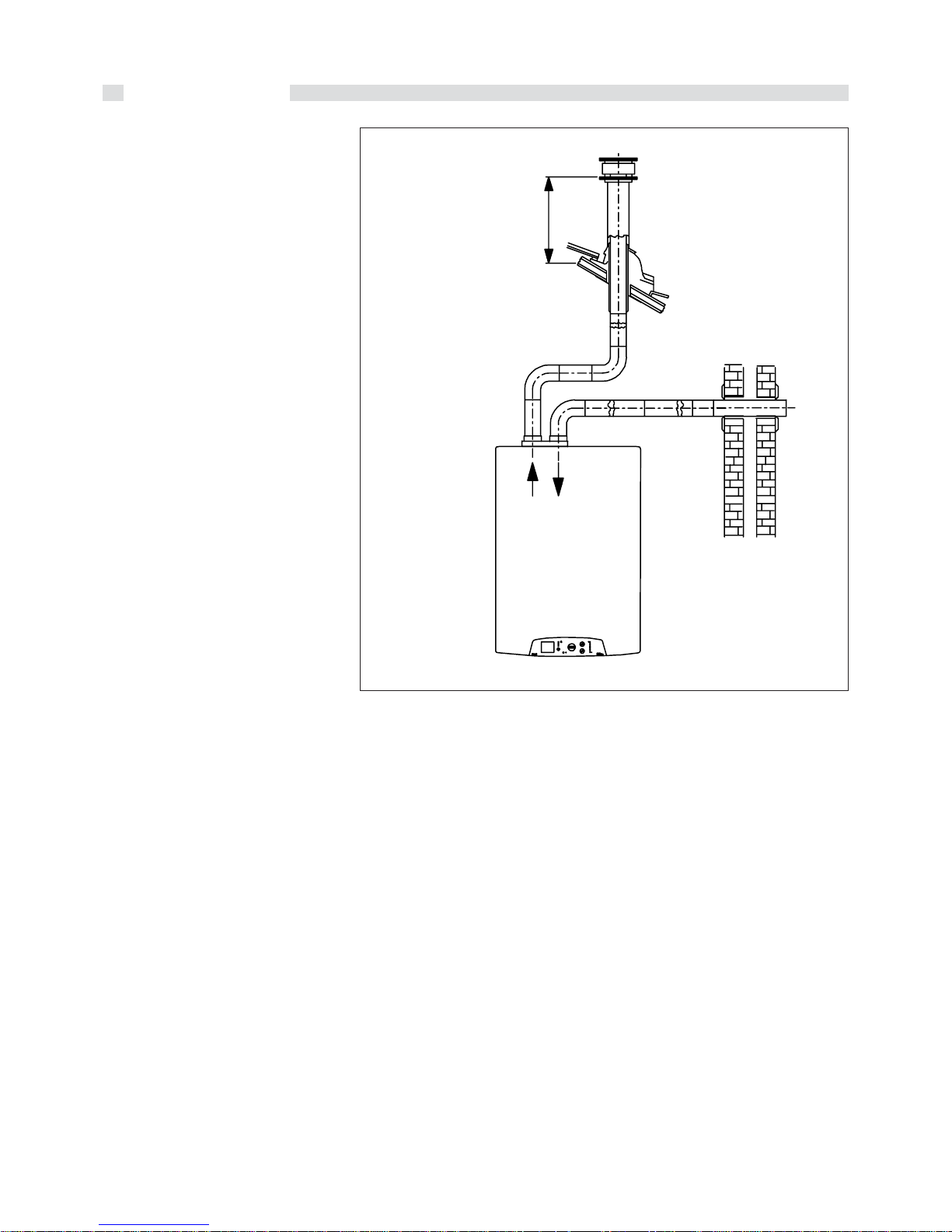
Direct emission into the atmosphere
Natural draught boilers can discharge
combustion products directly into the atmosphere using a duct, which goes through
the outside walls of the building, connected
to a flue exhaust terminal.
The exhaust duct must also comply with the
following requirements:
- the sub-horizontal part inside the building
must be as short as possible (no more
than 1 m);
- for boilers with vertical discharge, such
as boilers Dua plus B, there must be no
more than 2 direction changes;
- it must receive the discharge from a
single boiler;
- the part going through the wall must be
protected by a sheath duct; the part of
the sheath duct facing the inside of the
build-ing must be sealed and the part
facing outwards must be open;
- the final section, on which the draught
terminal will be fixed, must protrude from
the wall of the building for a length of at
least twice the diameter of the duct;
- the draught terminal must overlap the
connection to the boiler by at least 1.5 m
(see fig. 8).

Installation info
11
fig. 6
fig. 7
600
167
880
Ø 140
182
475
2 Ø min.
Slope
min. 3%
Ø
1,5 m min.
2 Ø
1 m max.
1,5 m min.
2 Ø
Ø
Slope
min. 3%
1 m max.
2 Ø min.
> 3 Ø
> 3 Ø
®
plus
DUA
®
plus
DUA
®
plus
DUA
WARNING:
The boiler is fitted with an automatic safety
reset device as protection against spillage
of combustion products inside the building.
In case of the device operation, the boiler
will remain in lock-out position indicating the
anomaly on the display.
After 15 minutes the boiler will be reset
automatically.
It is absolutely forbidden to
by-pass the smoke
thermostat.
If the boiler cuts off regularly,
it is necessary to ask a technician for a check
of the flue gas exhaust duct. This duct may
be obstructed or may be unsuitable for the
discharge of flue gas into the atmosphere.
UNICAL refuses all liability for
damage caused as a result of
incorrect installation, use, modi-
fication of the boilers or for non-observance
of the instructions provided by the manufacturer or applicable installation regulations
DIMENSIONS FOR CONNECTING FLUE GAS DUCT

Installation info
12
fig. 8
The DUA plus B is a forced draught, room
seled boiler; so it does not need particular
ventilation openings for the combustion air,
in the room in whichit is installed.
POSITIONING OF TERMINALS FOR TYPE ‘’C’’ BOILERS
Position of the terminalPosition of the terminal
Position of the terminalPosition of the terminal
Position of the terminal
Min. DistancesMin. Distances
Min. DistancesMin. Distances
Min. Distances
mm
- Under a window A 600
- Under a ventilation opening B 600
- Under a gutter C 300
- Under a balcony (1) D 300
- From an adjacent window E 400
- From an adjacent ventilation opening F 600
- From vertical or horizontal air pipes or drains (2) G 600
- From an external corner of the building H 300
- From an internal corner of the building I 1000
- From the ground or from another floor L 1800
- Between two vertical terminals M 1500
- Between two horizontal terminals N 1000
NOTES
(1) Terminals below a practicable balcony shall be arranged in such a way as to assure that the total run of smokes, from their outlet
from terminal up to outlet from balcony external perimeter, including the height of protection baluster, if any, is not less than 2 m.
(2) Distances of not less than 500 mm shall be adopted in placing the terminals, due to the proximity to materials subject to the action
of products of combustion such as plastic gutters or waterspouts, wooden jetties, etc.) unless adequate screening measures are
taken for the said materials.
The forced draught, room seled boilers, normally should evacuate the smokes on the
roof of the building.
When, in some country, it is allowed to evacuate on the front of the building, the following distances of the terminals, have to
be complied with:
TERMINALS POSITION

Installation info
13
2.2.5 - SMOKE DISCARGE AND AIR
SUCTION DUCTS CONFIGURATION
TYPES C12, C32, C42, C52, C82
The DUA plus boiler has been approved for
the following air suction and smoke
evacuation tipes:
C12
Boiler designed for connection to horizontal
exhaust and suction terminals directly into
the atmosphere using coaxial or dual ducts.
The distance between the air intake duct
and the flue gas outlet duct must be at least
250 mm and both end sections must
be located within a 500 mm square.
C32
Boiler designed for connection to vertical
discharge and suction outlets directly into
the atmosphere using coaxial or dual ducts.
The distance between the air intake duct
and the flue gas outlet duct must be at least
250 mm and both end sections must be
located within a 500 mm square.
C42
Boiler designed for connection to collective
chimneys including two ducts,
one for the suction of combustion
air and the other for the exhaust
of the combustion products,
through coaxial or dual ducts.
The chimney must comply with relevant
applicable law provisions.
C52
Boiler with separate combustion air
suction and combustion product
exhaust ducts.
These ducts can discharge into areas
with different pressure.
The dual ducts must not be located
on two opposite walls.
C82
Boiler designed for connection to an air
supply terminal and fitted to an individual
or shared chimney.
The chimney must comply with relevant
applicable law provisions.
type
C12
type
C32
type
C52
type C82
type
C42

Installation info
14
fig. 10
fig. 9
Ø 100
95
880
182
600
475
minimo 500
®
plus
DUA
167
DIMENSIONS FOR CONNECTION OF THE COAXIAL DUCTS
Type C12
The maximum autorised length for the
horizontal coaxial pipes is 3 meters; for each
supplementary bend the maximum length will
be reduced by 1 meter; furthermore the pipe
shal have a downward inclination of 1% on
the outlet direction in order to avoid the rain
enter the pipe.
For installations with horizontal coaxial pipe
with length between 1 m, it is necessary to
place, inside the fan outlet, the diaphragm
supplied with the boiler (see fig. 9).
Type C32
The maximum allowed length of the coaxial
vertical pipes is 5 meters, included the roof
terminal; for each supplementary bend the
maximum allowed length will be reduced by
1 meter.
For installations with coaxial ducts having a
length between 1.5 m, it is necessary to
place, inside the fan outlet, the diaphragm
supplied with the boiler (see fig. 9).
2.2.7 - SMOKE DISCHARGE SYSTEM
FORCED DRAUGHT BOILERS
C12: between 0.5 and 1 m
with
diaphragm
Ø 40 L m
ax = 3 m
Neoprene
Diaphragm
C12: between 1.2 and 2.5 m
with diaphragm Ø 40 L max = 3
Diaphragm
gasket

Installation info
15
fig. 11
fig. 12
600
475
880
120
167
Ø 80
182
®
plus
DUA
2.2.8 - SMOKE EVACUATION
THROUGH TWO SEPARATE
DUCTS Ø 80
(Type B accessories)
NB: The maximum allowed pressure
drop, according to the installation
type, must be equal to the value
indicated in the installation
examples given on page 17.
For installations with smoke
evacuation through separate
ducts, whose pressure drop value
is between 15 Pa and 30 Pa, it is
necessary to fit a diaphragm,
supplied with the boiler, inside the
smoke outlet (see fig. 11).
Diaphragm
Neoprene
gasket
Diaphragm
From
ΔΔ
ΔΔ
Δ
P=40 Pa
DIMENSIONS FOR CONNECTION THE AIR INTAKE AND THE FLUE GAS DISCHARGE WITH DUAL DUCTS
Installation info
16
fig. 13
>
500
_
Hmin. = 165 mm
CONFIGURATIONS FOR SEPARATE
PIPES (SUCTION AND OUTLET) Ø 80
Example N.1
Primary air suction from perimeter wall and
flue gas discharge on roof.
Maximum allowable pressure loss:
65 Pa
Example N.1

Installation info
17
fig. 14
135
45
Hmin. = 165 mm
250 min.
Example N.2
Primary air intake from an outer wall and
smoke evacuation through the same wall.
Maximum allowed pressure drop: 72Pa
CALCULATION OF PRESSURE LOSS
FOR DISCHARGE & SUCTION
DUCTS
Bear in mind the following parameters
when calculating pressure losses:
- for each metre of duct with Ø 80 (both
suction and discharge) the pressure loss
is 2 Pa;
- for each 90° Ø 80 (R=D) bend with long
radius, the pressure loss is 4 Pa;
- for the Ø 80 L = 0.5 m horizontal air inlet
terminal, the pressure loss is 3 Pa;
- Ø 80 L = 0.6 m horizontal discharge end
section, the pressure loss is 5 Pa;
NB: These values refer to discharges
through original UNICAL non flexible and smooth ducts.
In both of the following examples
the hypotized compositions of the
intake and evacuation ducts are
possible because the total pressure
loss is lower than 72 Pa, which is
the maximum allowed pressure loss.
Example of check using wide radius
bends:
- 15 m duct Ø 80 x 2 = 30 Pa
- 2x90° Ø80 long radius bends 2x4= 8 Pa
- horizontal Ø 80 air inlet terminal = 3 Pa
- horizontal Ø 80 terminal = 5 Pa
Total pressure loss = 46 Pa
Example N.2

Installation info
18
fig. 17
1
2
fig. 15
1
2
TSC0210C
ADA0160C
Analyser
probes
Analyser
probes
Smokes
Air
2.2.9 - ON SITE COMBUSTION
EFFICIENCY MEASUREMENT
Coaxial ducts
(Type A accessories)
To determine combustion efficiency the
following measurements must be made:
- the combustion air temperature measured
in hole 2 (see fig. 15).
- the flue gas temperature and CO2 %
measured in hole 1 (see fig. 15).
Make these measurements with the
boiler running in a steady state
condition.
(Type B accessories)
Separate ducts
To determine combustion efficiency the
following measurements must be made:
- the combustion air temperature measured
in hole 2 (see fig. 15).
- the flue gas temperature and CO2 %
measured in hole 1 (see fig. 15).
Make these measurements with the
boiler running in a steady state
condition.
Analyser
probes
2.2.10 - GAS SUPPLY LINE
The gas supply line must have a diameter
equal or larger than the one used in the boiler.
Comply with the applicable local installation
requirements which shall be considered as
having been incorporated in full in this
manual.
Before opening the internal gas supply
system; i.e. before connecting the gas
meter, all seals must be checked.
If any part of the system is concealed the
seals must be checked before the pipes
are covered.
The seal test must be conducted using air
or nitrogen at a pressure of at least 100
mbar.
The commissioning of the boiler also
includes the following operations and
checks:
- Opening of the gas gate valve and venting
of the air contained in the piping and boiler,
proceding appliance by appliance.
- Check, with the gate valve of all the
appliance
DIAGRAM FLOW RATE/MANOMETRIC HEAD AVAILABLE FOR C.H. SYSTEM
= By-Pass CLOSED
= By-Pass OPEN
..............
Flow rate l/h (Q)
Available Manometric Head m c.e.
2.2.11 - HYDRAULIC CONNECTIONS
Before installing the boiler we recommend
that the system be cleaned to remove any
impurities which could originate from
components and which could risk damaging
the circulating pump and heat exchanger.
HEATING
The heating flow and return must be
connected to the relevant ¾” connections
of the boiler M and R (see fig. 5).
When determining the size of the heating
circuit pipes it is essential to bear in mind
the pressure losses induced by radiators,
any thermostatic valves, radiator cut-off
valves and the configuration of the system.
In the boiler, between the flow and return
pipes,an automatic bypass device is fitted
(a differential valve with a flow rate of
about 150 l/h) which guarantees always
minimum flow rate through the heat
exchanger, also in the case, for instance,
that all the thermostatic valves fitted on the
radiators, are closed.
Off, that there are no gas leaks.
During the 2nd quarter of a hour from the
beginning of the test no pressure reduction
is to be detected on the gas pressure
gauge. If gas leaks have to be found, use
only water soap solution or any other
specific gas leak detector which can be
available on the market. Never look for gas
leaks using a nacked flame.
Installation info
19
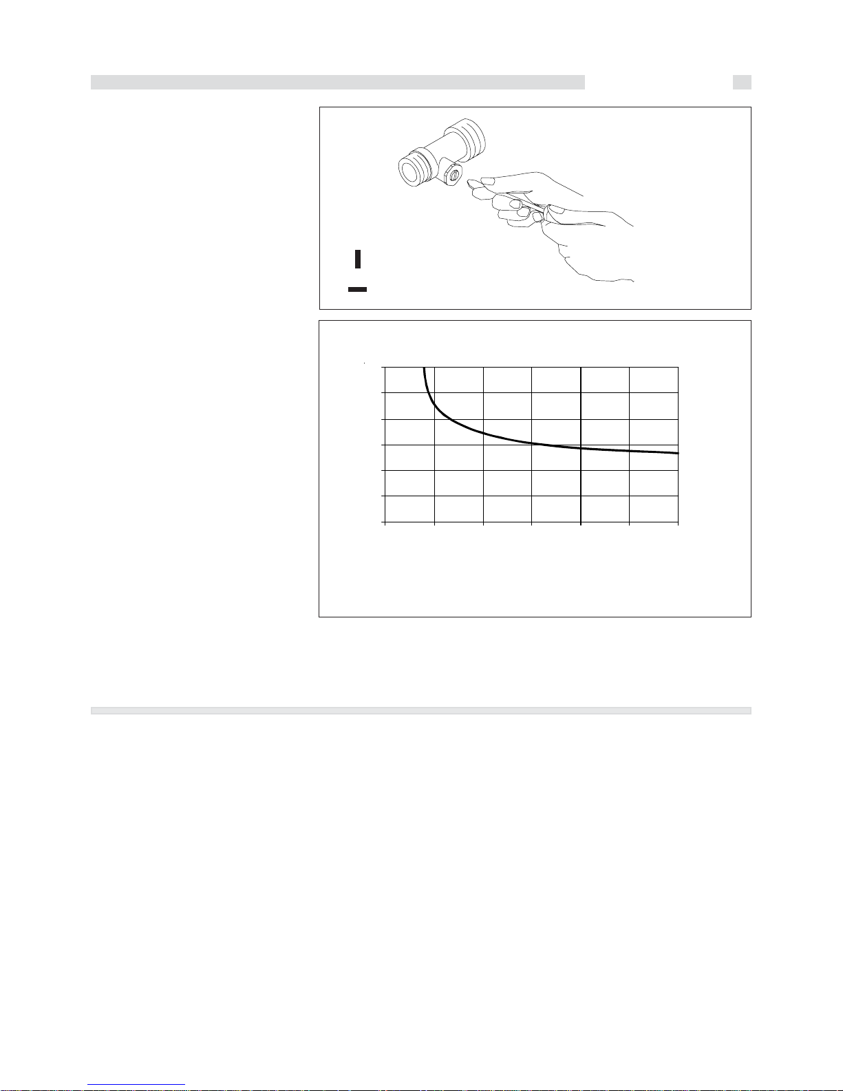
D.H.W. PRODUCTION
Cold water temperature = 15 °C
Quantity drawn at 14 litres/min
fig. 19
Drawing temperature °C
Quantity drawn in litres
By-Pass CLOSED
By-Pass OPEN
fig. 18
It is possible to adjust the by-pass by
acting onto the adjusting screw (see fig.
18).
D.H.W. (Domestic Hot Water)
Inlet and Outlet and of D.H.W. must be
connected to the relevant ½” connections
of the boiler C and F (see fig. 5).
The pressure in the water mains must be
between 1 and 3 bar (in case of higher
pressure it is necessary to fit a PRV
(Pressure Reducing Valve).
We recommend that the discharge of the
safety valve mounted in the boiler be
conveyed into the sewer.
If this precaution is not taken, activation of
the safety valve may result in flooding of
the room where the boiler is installed.
UNICAL shall not be held responsible for
damage caused by non-observance of this
technical precaution.
The hardness of the supply water affects
the frequency of the cleaning of the heat
exchanger; the opportunity to install a water
softning device depends on the
characteristics of the water it self.
NOTE:
With a water whose hardness is higher
than 20°f the use of a softner is strongly
recommended
60
55
50
45
40
35
0 50 100 150 200 250 300
6
5
2.2.12 - ELECTICAL CONNECTIONS
The electrical connections of DUA plus 30
μtank are shown in the clause ‘’WIRING
DIAGRAMS’’ (par. 2.3 - pag. 20).
The boiler must be connected to
the mains supply at 230 V - 50 Hz. This
connection is to be perfectly done, as
foreseen by the IEC and local rules and
must be earthed.
This fundamental requirement for safety
purposes must be checked; in case of
doubt, ask for a professionally qualified
technician to check the electrical system.
UNICAL disclaims all liability for damage or
caused by failure to earth the system.
Gas, domestic water and central
heating pipes are not suitable for
earthing purposes.
The boiler is supplied with 1.5 m long
3x0,75mm² cord.
PhasePhase
PhasePhase
Phase and
Neutral Neutral
Neutral Neutral
Neutral must
compulsory be connected to
PhasePhase
PhasePhase
Phase and
NeutralNeutral
NeutralNeutral
Neutral of the supply socket.
A double pole switch with a distance
between the contacts higher than 3 mm,
must be installed upstream the boiler to
enable all maintenance operations to be
carried out safely.
Installation info
20
fig. 20
A6
65432 17
7654321
A2
BLUE
BROWN
SS
E. RIV.
TEFLON WHITE
ROD
A9
BROWN
V
BLUE
YEL/GREEN
32 1
SR
GREEN
BROWN
WHITE
BLUE
87654 321
A3
4321
A1
54321
A4
WHITE
WHITE
WHITE
WHITE
WHITE
BLUE
BLUE
BLUE
BROWN
GREEN
VERSION E
TN
VERSION E
TFS
5432 1
DK
TF
TL
PV TL
MD
A8
65432 1
BROWN
BLUE
YEL/GREEN
BROWN
BLUE
YEL/GREEN
PS
PR
BROWN
E. ACC. 1
TEFL ON R ED
TEFLON RED
V2V1
E. ACC. 2
BLUE
BROWN
BLUE
YEL/ GREEN
DISPLAY PCB
BROWN
SE
TA 1
BLAC K
BLUE
YEL/GREEN
L1
N
L1
N
ALIME NTATION
230 V - 50 Hz
IG
54321
GND1
GND2
GND4
ROD
N
Y2
GND5
L1 EXT
SENSOR
Y1
A8
7654 321
43217654
8
321
2 1
21
A6
A9
A3 A1 A2 A4
TA 2
EVZ
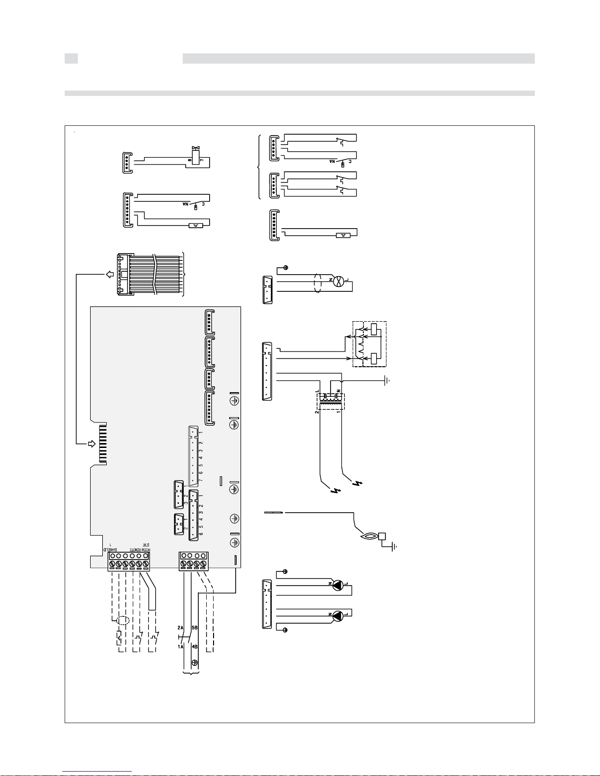
2.3 - ELECTRICAL WIRING
2.3.1 - ACTUAL CONNECTION DIAGRAM
KEY
A1…A8 = Utility connectors
ROD = Ionization electrode connection
on the main board
Y1 = Room thermostat and outer
sensor connectors
Y2 = Voltage connector
DK = Pressure switch for low water
level
E. RIV. = Ionization electrode
E.ACC1 = Ignition el ect rode
E.ACC2 = Ignition el ect rode
MD = Modulating coil
PR = Heating pump
PS = Sanitary pump
PV = Fan pressure switch (only fan
assisted version)
SE = Outer sensor (optional)
SS = D.H.W. temperature sensor
SR = C.H. temperature sensor
TA = Room thermostat (optional)
TF = Flue gas antispillage thermostat
(natural draught version)
TL = Limit thermostat
V = Fan (only fan assisted version)
VG = Gas valve
JP1 = Jumper for on/off or modulating
chronothermostat selection (see
page 22)
JP2 = Jumper for boiler version
selection (natural draught or fan
assisted)
Installation info
21
fig. 21
AZZURRO
AZZURRO (N)
GIA/VERDE
GIA/VERDE
CAVO PVC 3x0,75 Ø
MARRON E
MARRONE ( L)
A
B
C
D
Y2
GND 1
E
F
B
C
D
EF
®
plus
DUA
MAX
MAX
80° 60°
65°
70° 55°
60° 50°
50° 45°
40° 40°
30° 35°
20°
-20 °C
10 °C
0 °C
-10 °C
MIN - MAX
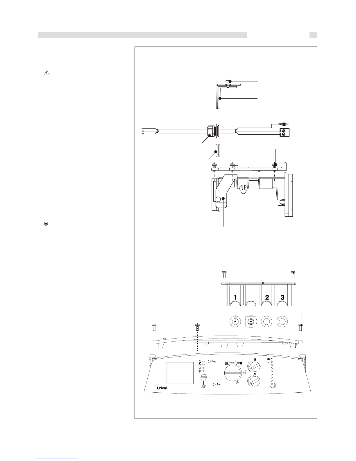
GENERAL INFORMATION ON THE
ELECTRICAL CONNECTIONS
Access to the supply terminal block
- WARNING! Disconnect power supply
- Remove the front casing.
- Widen the two plastic flaps (A); pull frontwards the panel board and rotate it
downwards.
- To get access directly to the connection
zone, unscrew the two screws (B) and
remove the cover (C); if this isn't enough,
unscrew the five screws (D) to get
access completely inside the panel board
(act carefully).
Replacement of the supply cable
When replacing the supply cord, the UNICAL
original one, Part. code 00610308, must be
used.
- Get access to the supply terminal block
Y2 (see previous paragraph).
- Insert the new power supply cord through
the extractable cable gland E
- Pul out the terminal block Y2 and make the
connections respecting the position and the
colours. The female faston of the earthing
wire must be introduced on the tab GND 1.
L1= phase = brown - terminal Y2 - 1
N =neutral = bleu - terminal Y2 - 2
= earth = yellow/green - tab GND1
Room thermostat connection
(ROOM STAT)
- Get access to the terminal block Y1
- Remove the link between terminals 4 - 5.
- Insert the room thermostat cable TA
through the extractable gland, supplied
with the boiler, and connect it to the
terminals 4 and 5.
- WARNING! If an ON/OFF room stat is
used, the jumper JP1 of the modulating
PCB must be positioned between pins 2
and 3 (see fig. 23).
External sensor connectionEXT SENS)
- Get access to the terminal block Y1
- Insert the external sensor cable through
the extractable cable gland, supplied with
the boiler, and connect it to the terminals 2
and 3 of the block Y1; if the cable is of
shielded type, then connect the shield to
the terminal 1 of the block Y1.
For the connection of the ROOM STAT and
the EXT SENSOR, replace the plastic plugs F
of the panel board with the cable glands
supplied with the boiler.
ACCESS TO THE MODULATING PCB
Front view
Panel board side view

Installation info
22
2.3.2 - POSITIONING OF THE JUMPERS
fig. 23
JUMPERS ON THE DISPLAY PCB
JP4 : GAS TYPE SELECTION
Naturl gas: Jumper on NAT (standard supply position)
Liquefied Petroleum Gas: move jumper to LPG position
The standard supply position correspond to the gas type shown on all
the labels within the boiler
JP3 : EXTRNAL TEMPERATURE COMPENSATION FOR OUTER SENSOR
Boiler with outer temperature sensor: jumper on
J
Boiler without outer temperature sensor: jumper on OFF
JP2 : SELECTION OF PUMP OPERATION MODE
If pump has to work continuously: jumper on 1
If pump has to stop after an overrun of 5 min since the stop of the heating
demande: jumper on pos. 2 (standard supply position)
JP1 : CHRONOSTAT FUNCTION (do not change posion of the jumper)
This function is not yet available.
Jumper on (Standard supply position: for a good working keep the jumper in
this position).
T°C0123456789
0 32755 31137 29607 28161 26795 25502 24278 23121 22025 20987
10 20003 19072 18189 17351 16557 15803 15088 14410 13765 13153
20 12571 12019 11493 10994 10519 10067 9636 9227 8837 8466
30 8112 7775 7454 7147 6855 6577 6311 6057 5815 5584
40 5363 5152 4951 4758 4574 4398 4230 4069 3915 3768
50 3627 3491 3362 3238 3119 3006 2897 2792 2692 2596
60 2504 2415 2330 2249 2171 2096 2023 1954 1888 1824
70 1762 1703 1646 1592 1539 1488 1440 1393 1348 1304
80 1263 1222 1183 1146 1110 1075 1042 1010 979 949
90 920 892 865 839 814 790 766 744 722 701
Relation between the temperature (°C) and the resistance (Ohm) of the heatin temp. sensor SR and the D.H.W. temp. sensor
SR. Example: At 25 °C the nominal resistance is 10067 Ohm - At 90 °C the resistance is 920 Ohm.
TABLE OF THE RESISTANCE VALUES ACCORDING TO THE TEMPERATURE OF THE HEATING SENSOR (SR) AND
D.H.W. TEMPERATURE SENSOR (SS)
NAT
GPL
OFF
JP4
JP3
J
JP2
JP1
1
2
1
2
POSITIONING OF THE JUMPER

Installation info
23
fig. 23
boiler
safety
valve
Filling
cock
tank
draining
valve
Adjustable
by-pass
R
F
G
C
M
manometer
boiler
draining
valve
2.4 - FILLING THE SYSTEM
After completing all the connections of the
system the heating circuit can be filled.
This filling operation must be performed
with care as follows:
- open the air vents of the radiators and
check that the automatic air vent in the
boiler is works properly;
- gradually open the water tap and check
operation of any automatic air vents
installed in the system;
- close the air vents on the radiators as
soon as water comes out;
- use the pressure gauge on the boiler to
check that the pressure has reached the
value of 0.8/1bar;
- close the water inlet tap and then release
the air again through the radiator air
vents;
- after switching on the boiler and after the
system has reached the correct
temperature, stop the pump and repeat
the air relief operations;
- let the system cool down and then adjust
the water pressure to 0.8/1 bar.
This must be performed when the system
is cold. Use the temperature and pressure
gauge on the boiler to read the pressure
value of the circuit.
WARNING
The minimum water pressure switch does
not give electrical impulse to the burner to
ignite when the pressure is lower than 0.4
bar. The pressure of the water in the C.H.
system must not be lower than 0.8/1bar; if
this value is lower use the water filling tap
on the boiler to adjust the pressure.
This must be performed when the system
is cold. Use the temperature and pressure
gauge on the boiler to read the pressure
value of the circuit.
NB: NB:
NB: NB:
NB:
AfAf
AfAf
Af
ter a given period of inactivityter a given period of inactivity
ter a given period of inactivityter a given period of inactivity
ter a given period of inactivity
and without electrical supply theand without electrical supply the
and without electrical supply theand without electrical supply the
and without electrical supply the
pump could be blocked.pump could be blocked.
pump could be blocked.pump could be blocked.
pump could be blocked.
Before switching on the boiler it isBefore switching on the boiler it is
Before switching on the boiler it isBefore switching on the boiler it is
Before switching on the boiler it is
important to restart the pump asimportant to restart the pump as
important to restart the pump asimportant to restart the pump as
important to restart the pump as
follows:follows:
follows:follows:
follows:
- loosen the protection screw in the
centre of the pump motor,
- insert a screwdriver in the hole and then
manually rotate the pump shaft
clockwise.
Once the pump has been restarted tighten
the protection screw and check that there
are no water leaks.
WARNING
Once the protection screw hasOnce the protection screw has
Once the protection screw hasOnce the protection screw has
Once the protection screw has
been removed a little water maybeen removed a little water may
been removed a little water maybeen removed a little water may
been removed a little water may
leak out. Before replacingleak out. Before replacing
leak out. Before replacingleak out. Before replacing
leak out. Before replacing
the casing of the boiler dry any wetthe casing of the boiler dry any wet
the casing of the boiler dry any wetthe casing of the boiler dry any wet
the casing of the boiler dry any wet
surfaces.surfaces.
surfaces.surfaces.
surfaces.
- there are no gas leaks;
- the external mains switch is on;
- the boiler’s safety valve is not locked;
- there are no water leaks.
SWITCHING ON AND OFF
To switch on and off the boiler follow the
indications in the “Users’ Instructions”.
- the supply voltage of the boiler is 230 V-
50 Hz;
- the system is correctly filled with water
(pressure at the gauge 0.8/1 bar);
- any gate valves of the system are open;
- the mains gas corresponds to that with
which the boiler has been adjusted;
otherwise convert the boiler to use the
gas available on site (see:
“MODIFICA TION FOR OTHER GASES “):
this operation must be performed
by qualified technicians;
- the gas supply taps are open;
2.5 - STARTING THE
BOILER
PRELIMINARY CHECKS
Before starting the boiler check that:
- the boiler installation has been made in
accordance with all the applicable
regulations concerning water and gas
installation, smoke evacuation and
electrical installation
- the flue gas exhaust duct and its
terminal are installed correctly: when
the boiler is switched on there
must be no leakage of any
combustion products from any
seals;

24
Adjustment info
fig. 25
2.6 - ADJUSTING THE
BURNER
All the instructions below are for the
exclusive use of qualified technicians.
All the boilers leave the factory adjusted
and tested.
If it is necessary to change the adjustment
due to changes in the gas or adaptation to
the supply network conditions, it will be also
necessary to re-adjust the gas valve.
Attention: during this re-adjustment do
not draw any Domestic Hot Water.
For this reason it’s necessary to know the
boiler operation in service mode.
In order to activate this function, push and
keep hold the service push button, on the
control panel, for 3 seconds: the service
mode green led will be continuously .lighted
( continuous)
and the boiler will
operate at the maximum capacity. Then
push once again the same button: the
service mode green led will start blinking
( blinking)
. The service mode function
remains active for 15 minutes.
For cleaning this function before this fixed
period, push the reset button: the service
mode led will switched off
( off).
.
To correctly adjust the gas valve, follow the
steps below:
A) Maximum output adjustment
- check the value of the supply pressure
(see table NOZZLES - PRESSURES);
- Remove the cover (A) protecting the
pressure regulator on the top of the
modulating coil.
- Connect a manometer at the outlet gas
valve pressure nipple.
- Activate the service mode function to
the maximum capacity (service mode led
continuous lighted).
- When the burner is ON, check that the
“MAXIMUM” pressure value
corresponds
to that indicated on the table “NOZZLES
- PRESSURES”:
- Adjust, eventually, the value rotating the
“C” nut (fig. 25) by clockwise rotation the
gas pressure increases, by anticlockwise
rotation the gas pressure decreases.
B) Minimum output adjustment
- Operate the boiler in service mode at
minimum output (service mode led
blinking).
- When the burner is ON, check that the
“MINIMUM” pressure value corresponds
to that shown on the table “NOZZLES
PRESSURES”:
- Adjust, eventually, the value by keeping
locked the ‘’C’’ nut with a 10 mm open
wrench and rotating the “B” screw (fig.
25) by clockwise rotation the gas
pressure increases, by anticlockwise
rotation the gas pressure decreases.
C) Ending of basic adjustments
- check the min. and max. pressure values
of the gas valve by acting the service
mode
- if necessary make any fine adjustments
- Clear the service mode function by
pushing the reset button or switching off.
- Remove the plastic pipe from pressure
test nipple and close the inner screw;
fig. 24
MP
Carry out the
adjustment Min.
output blocking the
position of the
retaining nut “C”
with a 10 mm.
spanner to avoid
uncalibration and
use a scewdriver
on the “B screw
A
- Use soap solution tocheck for gas
leaks.
Adjustment Max.
output “C”
retaining nut with
10 mm. wrench
SERVICE MODE AT
MAX CAPACITY
MIN - MAX
MIN - MAX
SERVICE MODE AT
MIN CAPACITY
SERVICE MODE
DISABLED
(BEFORE 15 MINUTES)
MIN - MAX
MP =
pressure test nipple
PRESSURE TEST NIPPLE
MODULATING COIL
GAS VALVE
Outlet
pressure
test
nipple
Inlet
pressure
test nipple
B = Minimum
pressure
adjust. screw
(red)
C = Maximum
pressure
adjust. nut
(wrench 10 mm)
25
Adjustment info
fig. 27
fig. 26
1612 1713 1814 1915 20 21 2522 2623 2724 28
BTFS 28
PROPAN
BUTAN
NAT. GAS
5
10
15
20
25
30
35
40
0
Power supply (kW)
Burner pressure (mbar)
CAP
CH - POWER
1612 1713 1814 1915 20 21 2522 2623 2724 28
BTN 28
PROPAN
BUTAN
NAT. GAS
5
10
15
20
25
30
35
40
0
Power supply (kW)
Burner pressure (
m
bar)
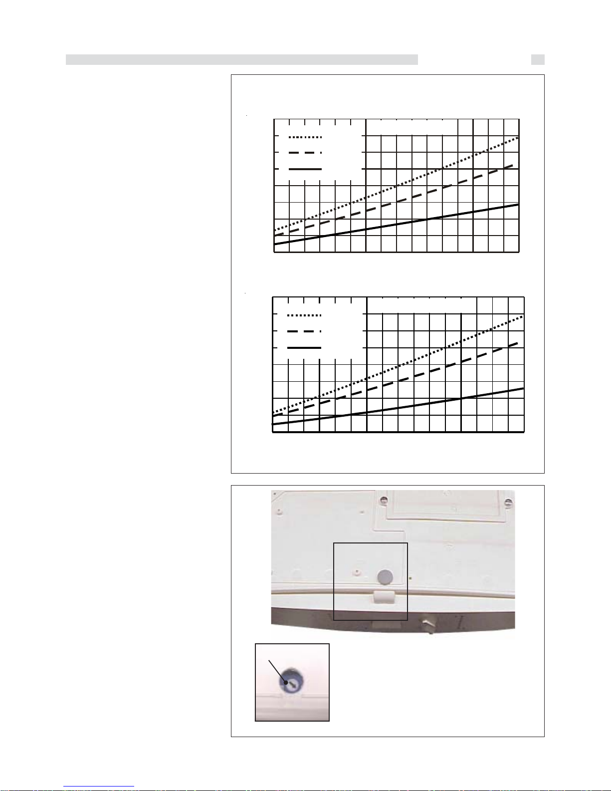
2.7 - ADAPTING THERMAL
POWER TO THE HEATING SYSTEM
With the heating system cold.
Connect the pressure gauge to the burner
as shown in fig. 24, switch on the boiler in
heating mode and proceed as follows.
- Wait about two minutes to allow the pressure to reach the operating value.
- Read the pressure measured and check
that the thermal power generated by the
boiler suits the installation requirements.
- If necessary – but this is not compul-
sory – you can regulate the potentiometer CH POWER on the modulation board
to adjust the thermal power to the heating
system. Turn the potentiometer clockwise
(seen from the front) to increase the
pressure or anticlockwise to decrease
it.
Note
Since the boiler is the modulating type, it
automatically adapts the thermal power
to the features of the heating system. By
operating potentiometer CH POWER you
effectively limit the maximum power of the
boiler and hence its pickup capacity.
Using the pressure/thermal power graph
(fig. 26)
Assuming that the heating system has a
total absorption of 18 kW, using the graph
in figure you can determine the maximum
pressure at which the burner can be set.
Example 1
If the boiler runs on methane gas, adjust
the potentiometer CH POWER to set the
pressure to 7,3 mbar for version TN and
to 7,1 mbar for version TFS.
Example 2
If the boiler runs on butane gas, adjust
the potentiometer CH POWER to set the
pressure to 12,5 mbar for version TN and
to TFS.
Example 3
If the boiler runs on propane gas, adjust
the potentiometer CH POWER to set the
pressure to 15,3 mbar for version TN and
to 15,5 mbar for version TFS.
GAS PRESSURE BURNER DIAGRAM CORRESPONDING TO
THE SYSTEMS OUTPUT

26
Adjustment info
fig. 28
DUA plus BTN 28
Metano (G20)
Propano (G31)
Butano (G30)
12,5 - 27,9
12,5 - 27,9
12,5 - 27,9
14,5 - 31
14,5 - 31
14,5 - 31
20
37
29
15
15
15
1,30
0,76
0,76
NO
NO
NO
2,3
7,8
5,8
9,7
34,3
27,3
1,53 m³/h
1,13 kg/h
1,14 kg/h
3,28 m³/h
2,41 kg/h
2,44 kg/h
DUA plus BTFS 28
Metano (G20)
Propano (G31)
Butano (G30)
12,9 - 28,8
12,9 - 28,8
12,9 - 28,8
14,5 - 31
14,5 - 31
14,5 - 31
20
37
29
15
15
15
1,30
0,76
0,76
NO
NO
NO
1,9
7,7
6
10,6
35,3
27,6
1,53 m³/h
1,13 kg/h
1,14 kg/h
3,28 m³/h
2,41 kg/h
2,44 kg/h
1
2.8 - MODIFICATION FOR
OTHER GASES
The boilers are manufactured for the type
of gas specifically required upon order.
Any subsequent conversion must be
performed by qualified technicians who will
use the kits supplied by Unical and perform
the conversion and required adjustments
for correct preparation of the boiler for use.
To convert the boiler from one type of gas
to another proceed as follows:
for conversion from natural gas to
LPG
- remove the main burner;
- disassemble the 15 injectors "
11
11
1"of the
main burner and replace them with those
with a diameter corresponding to the
new type of gas (see table “INJECTORS PRESSURES”);
- reassemble the main burner;
- position the jumper on the modulation PCB
in the panel board as shown in fig. 23
- remove plug ‘’A’’ (fig. 25) on the gas
valve and fully tighten max pressure
adjustment nut ‘’C"
- check the pressure value upstream the
gas valve (see table “INJECTORS PRESSURES”) and adjust the min.
pressure of the burner as shown in
section " ADJUSTING THE BURNER”, by
screwing the nut "B" to increase or
unloosing the nut "B" to decrease the
burner pressure.
- check that the burner is functioning
properly;
- check that there are no gas leaks.
- tighten and seal the plug “A” (fig. 25) of
the modulating coil;
- when the conversion is completed, fill in
the label, supplied with the kit, with the
information required and stick it onto the
boiler alongside the data plate.
for conversion from LPG to natural
gas
- remove the main burner;
- disassemble the 15 injectors of the main
burner and replace them with those with
a diameter corresponding to the new
type of gas (see “INJECTORS PRESSURES”);
- reassemble the main burner;
- get access to the modulating PCB inside
the panel board and position the jumper
shown in thefig. 28;
- remove plug ‘’A’’ (fig. 25) from the gas
valve modulating coil and adjust the
maximum and minimum output s
described in paragraph 2.6;
NAT
GPL
JP4
- check that the burner is functioning
properly;
- check that there are no gas leaks.
- tighten the screw “A” of the plug of the
gas governor (fig. 25);
- when the conversion is completed, fill in
label, supplied with the kit, with the
information required and stick it onto the
boiler alongside the data plate.
NOZZLES - DIAPHRAGMS - PRESSURES - GAS FLOW RATES
The pressures at the burner indicated in the following table must be checked after the boiler has been operating for 3
minutes.
Type of
gas
Supply
pressure
(mbar)
No. of
Nozzles
Ø
Diaphragme
(mm)
Ø
Nozzles
(mm)
min.
(mbar)
max
(mbar)
Burner pressure
max.
min.
Gas
consumption
Output
min. - max
(kW)
Input
min. - max
(kW)
Type of
gas
Supply
pressure
(mbar)
No. of
Nozzles
Ø
Diaphragme
(mm)
Ø
Nozzles
(mm)
min.
(mbar)
max
(mbar)
Burner pressure
max.
min.
Gas
consumption
Output
min. - max
(kW)
Input
min. - max
(kW)
POSITIONING OF THE JUMPER

27
Service info
2.9 – FAULT FINDING CHART AND POSSIBLE SOLUTIONS
In case of fault lamp lighting depress the Reset push button and, while kipping it
depressed, look at the error code given by the flashing leds.
Note: The error code is given by the combination of two, three, four of five leds,
flashing on the temperature scale.
SIGNIFICATION OF THE ERROR CODE
Fault on the outer temperature
sensor (if connected)
POSSIBLE SOLUTION
The control of the flow temperature by
the outer sensor is non active. Call
the After Sale Service
BOILER STATUS
This fault does not cause the locking
of the boiler.
SIGNIFICATION OF THE ERROR CODE
Faulty flame control PCB
POSSIBLE SOLUTION
Replace the ignition and/or modulating
PCB
BOILER STATUS
The boiler is in lockout position
SIGNIFICATION OF THE ERROR CODE
Fault on the gas valve modulation
system (coil interrupted)
POSSIBLE SOLUTION
Replace the gas valve modulation
coil, after checking of the harness,
the supply tension and the gas
pressure.
BOILER STATUS
Chaudière fonctionnant à la puissance
mini.
SIGNIFICATION OF THE ERROR CODE
The air pressure switch is faulty or in
short circuit (only for TFS version)
POSSIBLE SOLUTION
Inspect the air pressure switch
operation
BOILER STATUS
The boiler is in lockout position
SIGNIFICATION OF THE ERROR CODE
Too high boiler temperature
POSSIBLE SOLUTION
Make sure the pump is properly
operating and the heat exchanger is
clean inside
BOILER STATUS
The boiler is in lockout position
SIGNIFICATION OF THE ERROR
CODE
Fault on the smoke evacuation
system; after 15 min there is an
automatic reset.
POSSIBLE SOLUTION
For TN version: check the
chimney draught
For TFS version: ascertain the
good operation of the fan and its
air pressure switch.
Depress the Reset button.
BOILER STATUS
The boiler is in lockout position
SIGNIFICATION OF THE ERROR CODE
The water pressure within the
installation is below 0.5 bar
POSSIBLE SOLUTION
Reinstate the water pressure through
the filling valve (accessible also to
the user) and look for possible water
leaks. If the problem is not solved
call the After Sale Service.
BOILER STATUS
The boiler is in lockout position
SIGNIFICATION OF THE ERROR CODE
Probable freezing of the primary heat
exchanger; temperature below 2°C
detected by the SR or SS sensors.
POSSIBLE SOLUTION
Cut the power supply, close the gas
valve and call the After Sale Service.
BOILER STATUS
The boiler is in lockout position
SIGNIFICATION OF THE ERROR CODE
Fault on the DHW temperature sensor
(SS)
POSSIBLE SOLUTION
Ascertain that the SS sensor has the
right resistance values shown on the
table of the resistance values and it
harness is correct (see table on page
14)
BOILER STATUS
The boiler is in lockout position
SIGNIFICATION OF THE ERROR CODE
Fault on the CH temperat. sensor (SR)
POSSIBLE SOLUTION
Ascertain that the SR sensor has the
right resistance values shown on the
table of the resistance values and its
harness is correct (see table on page
16).
BOILER STATUS
The boiler is in lockout position
SIGNIFICATION OF THE ERROR CODE
Alteration of factory parameters
POSSIBLE SOLUTION
None. Replace the modulating PCB
BOILER STATUS
The boiler is in lockout position
SIGNIFICATION OF THE ERROR CODE
Fault on the modulation system of the
gas valve.
POSSIBLE SOLUTION
Check first the modulating coil or its
harness are not earthed or in short
circuit: if this is the case replace
them. If no result, replace the
modulating PCB.
BOILER STATUS
The boiler is in lockout position
SIGNIFICATION OF THE ERROR CODE
Main PCB (modulation) is damaged.
POSSIBLE SOLUTION
Cut and reinstate the power supply to
the boiler: if no result, replace the
main PCB.
BOILER STATUS
The boiler is in lockout position
80° 60°
65°
70° 55°
60° 50°
50° 45°
40° 40°
30° 35°
20°
80° 60°
65°
70° 55°
60° 50°
50° 45°
40° 40°
30° 35°
20°
80° 60°
65°
70° 55°
60° 50°
50° 45°
40° 40°
30° 35°
20°
80° 60°
65°
70° 55°
60° 50°
50° 45°
40° 40°
30° 35°
20°
80° 60°
65°
70° 55°
60° 50°
50° 45°
40° 40°
30° 35°
20°
80° 60°
65°
70° 55°
60° 50°
50° 45°
40° 40°
30° 35°
20°
80° 60°
65°
70° 55°
60° 50°
50° 45°
40° 40°
30° 35°
20°
80° 60°
65°
70° 55°
60° 50°
50° 45°
40° 40°
30° 35°
20°
80° 60°
65°
70° 55°
60° 50°
50° 45°
40° 40°
30° 35°
20°
80° 60°
65°
70° 55°
60° 50°
50° 45°
40° 40°
30° 35°
20°
80° 60°
65°
70° 55°
60° 50°
50° 45°
40° 40°
30° 35°
20°
80° 60°
65°
70° 55°
60° 50°
50° 45°
40° 40°
30° 35°
20°
80° 60°
65°
70° 55°
60° 50°
50° 45°
40° 40°
30° 35°
20°
SIGNIFICATION OF THE ERROR CODE
Intervention of the safety thermostat
POSSIBLE SOLUTION
Make sure the water is circulating
through the heat exchanger and the
safety thermostat TL and its harness
are not interrupted. Check as well the
CH temperature sensor (SR).
BOILER STATUS
The boiler is in lockout position
80° 60°
65°
70° 55°
60° 50°
50° 45°
40° 40°
30° 35°
20°

28
Service info
3
C
A
P
fig. 29
M
N
B D
LI
HG
O
E
F
®
plus
DUA
MAX
MAX
80° 60°
65°
70° 55°
60° 50°
50° 45°
40° 40°
30° 35°
20°
-20 °C 10 °C
0 °C
-10 °C
MIN - M AX
A = Mode selector: Heating only- Heating + D.H.W.
- Antifrost - D.H.W. only
B = Heating temperature adjusting knob
C = D.H.W.temperature adjusting knob
D = Thermometer
E = Signal lamp of heating temperature scale
F = Signal lamp of D.H.W. temperature scale
G = Power ON signal l
amp (antifrost)
H = Burner in operation signal lamp
I = Fault indication lampe
L = Burner lockout warning lamp
M = Manual reset button
3.1 - PANEL BOARD
N = Special functions button (for service purposes)
O = Special functions signal lampe
(for service purposes)
P = Outer temperature selector (opérational only
if outer temperature sensor is fitted).
USER'S INSTRUCTIONS
By acting on the selector the operation mode
is choosen :
CENTRAL HEATING ONLY
With the mode selector in this position the
boiler works for Central Heating only.
CH & DHW
With the mode selector in this position the
boiler works for Central Heating and
Domestic Hot Water production
MODE SELECTOR:
CH ONLY - CH & DHW ANTIFROST - DHW ONLY
D.H.W. TEMPERATURE
ADJUSTING KNOB
With this knob it is possible to set the
maximum desired temperature in the boiler.
The setting range of this temperature is
between a minimum of 35°C and a maximum
of 65°C.
By rotating COUNTER-CLOCKWISE this
knob a minimum temperature of 35°C is
reached.
By rotating completely CLOCKWISE this
knob a maximum temperature of 65°C is
reached.
D.H.W. only
With the mode selector in this position the
boiler works for D.H.W. only.
HEATING TEMPÉRATURE
ADJUSTING KNOB
With this knob it is possible to set the
maximum desired temperature in the heating
circuit.
The setting range of this temperature is
between a minimum of 35°C and a maximum
of 85°C.
By rotating COUNTER-CLOCKWISE this
knob a minimum temperature of 35°C is
reached.
By rotating completely CLOCKWISE this
knob a maximum temperature of 85°C is
reached.
MAX
MAX
ANTIFROST
With the mode selector in this position the
boiler is not in operation: the antifrost
protection on the heating circuit only is
operational.
The antifrost protection system is
operational only if the boiler is feeded
with gas and electrical supply.

29
Service info
MANOMETER
It shows the water pressure inside the
heating circuit, whose value, in cold
condition,should not be lower than 0,8/1 bar.
Note that if the pressure decreases below
0,4/0,6 bar the boiler goes into lockout, not
allowing the ignition of the burner.
In this case reinstate the minimum required
filling pressure (0,8/1 bar) following the
instructions given on figure 23.
POWER ON SIGNAL LAMP
The function of this GREEN lamp is to show
that the power to the boiler is ON; to get the
boiler ON, position the "A" switch on "I"
position.
BURNER IN OPERATION
SIGNAL LAMP
The function of this GREEN lamp is to show
the proper operation of the burner
FAULT INDICATION LAMPE
The function of this RED lamp is to show an
operation fault.
By depressing on the RESET button (N) it is
possible to see the error code given by the
combination od the flashing leds. See
paragrapf 2.9 "FAULT FINDING AND
REPARATIONS".
BURNER LOCKOUT
WARNING LAMP
La fonction de ce témoin (ROUGE) est de
signaler l’intervention du dispositif de mise
en sécurité du brûleur.
MANUAL RESET BUTTON
This button allows the re-establishment of
the boiler operation after a lockout of the
burner control and to know the error code
given by the combination of the flashing leds
(burner lockout warning lamp). (témoin de
défaut allumé).
SPECIAL FUNCTIONS BUTTON
(FOR SERVICE PURPOSES)
This button allows the activation of the
SERVICE mode. (see paragraphe 2.6
"Burner adjustment). To reset this mode
before the expiring time depress on the
manual reset button.
WARNING! OPERATIONS RESERVED
ONLY TO SERVICE TECHNICIANS.
SPECIAL FUNCTIONS LAMP
(FOR SERVICE PURPOSES)
The function of this GREEN LAMP is to
indicate the activation of the SERVICE mode:
Continuous ON led = Max output for 15 min.
Flashing led = Minimum output for 15 min.
OUTER TEMPERATURE
SELECTOR (OPERATIONAL
ONLY IF OUTER SENSOR IS FITTED
Si the kit outer sensor is fitted, it is possible,
through this button, to set an outer
temperature value between -20°C
(completely counterclockwise) and 10°C
(completely clockwise).
If the outer temperature is equal or lower
than the one selected by the selector "Q"
the boiler temperature will be the one adjusted
on the "C" button.
If the outer temperature is higher than the
one selected by the selector "Q"the boiler
temperature will decrease linearly,
independently from the one adjusted on the
"C" button.
WARNING! OPERATIONS RESERVED
ONLY TO SERVICE TECHNICIANS.
MODULATING ROOM
THERMOSTAT
Warning: The mounting of a modulating
room thermostat imply the modification of
the functions of the heating temperature
adjuster (C) and D.H.W. temperature
adjuster (D).
Refer to the specific instructions supplied
with the modulating thermostat.
F
G
80° 60°
65°
70° 55°
60° 50°
50° 45°
40° 40°
30° 35°
20°
80° 60°
65°
70° 55°
60° 50°
50° 45°
40° 40°
30° 35°
20°
Through the thermometer scale of the panel
board it is possible to verify:
on the L.H. side scale the flow température
of the heating circuit, (F green led ON); on
the following example the temperature will
be 80°C.
on the R.H. side scale the outlet
température of the D.H.W. (G green led ON);
on the following example the temperature
will be 55°C.
On both cases, when two leds are ON the
temperature value will correspond to the
half of temperature difference betwee the
two ON leds.
80° 60°
65°
70° 55°
60° 50°
50° 45°
40° 40°
30° 35°
20°
Manometer
THERMOMETER
75°C
57,5°C

30
Service info
3.3 - IMPORTANT
SUGGESTIONS
AND NOTES
According to the national laws the service of
the heating appliances is compulsory.
This service consistes, as a minimum, of an
annual systematic visit, during which the
serviceman will control the safety equipment
and will make the cleaning of the combustion
circuit of the boiler.
This annual visit must be conducted within
the frame of a service contract, whose
different variants can include all or part of
the interventions concerning the
deplacement, the manpower and the spare
parts.
Only persons professionally qualified can
perform interventions on the gas valve
adjustment.
Check regularly the filling pressure of the
heating system through the manometer, and,
if necessary, reinstate the minimum
pressure value (0.8/1 bar in cold condition).
When the boiler stays without been used for
a long period, before putting the boiler in
operation make sure the pump is not jamed.
To make it free, if necessary, remove the
plug on the motor axis, put a screwdriver in
the slot foreseen on the motor shaft end and
try to rotate it manually, clockwise.
Once this dejamming operation has been
concluded, replace the protecting plug and
make sure there are no water leaks.
This operation has to be made,
preferably, by the Unical Service Center
charged for maintenance of the boiler.
The hardness of the domestic water
conditions the frequency of the cleaning of
the coil heat exchanger.
The convenience of water treatment must
be examined on the base of the water
characteristics.
N.B. If the water hardness is higher than
20°f (french), the adoption of a water softer
is strongly recommended.
FROST PROTECTION
If the boiler is connected to the mains and
the main switch "A" is in the antifrost position,
the heating pump is put into operation, for a
few seconds, every day, in order to impede
the pump jamming.
The boiler is equipped with an automatic
antifrost protection system: this system is
operational when the temperature detected
by the flow temperature sensor falls below
7°C by switching on the heating pump.
Below 5°C, the burner and the pump are
switced on, untill the temperature of 15°C, is
reached with a 15 min. maximum time limit.
After that, burner and pump are swiched off.
This cycle will be repeated, if necessary.
3.2 - IGNITION AND
EXTINCTION
BOILER IGNITION
Position the main switch"A" on "I" position .
SUMMER mode
(D.H.W.production only)
Select the SUMMER operation mode acting
on the selector "B".
Turn the temperature adjusting knob "D" on
the desired value.
By CLOCKWISE rotation the maximum
temperature is achieved.
WINTER mode
(Heating and D.H.W. production)
Select the WINTER operation mode acting
on the selector "B".
Turn both, the heating temperature adjusting
knob "C" and the D.H.W. temperature
adjusting "D" on the desired values.
By CLOCKWISE rotation the maximum
temperature is achieved.
HEATING mode
(Heating only is activated)
Select the HEATING only operation mode
acting on the selector "B".
Turn the temperature adjusting knob "C" on
the desired value.
By CLOCKWISE rotation the maximum
temperature is achieved.
The boiler gives always the priority to the
D.H.W. mode (see SUMMER operation).
Once the D.H.W. demande is satisfied, if the
room thermostat asks for heat, the boiler
goes to HEATING mode.
During the heating operation mode the boiler
switches ON and OFF controled by the
room thermostat and by the electronic P.C.B.
of the panel board.
The electronic control built-in the panel
board, depending on the detected
temperature difference between the one
adjusted on the knob and the one mesured,
puts the burner into operation plus or minus
frequently in order to satisfy very quickly
the heat demande by the room thermostat.
ANTIFROST mode
Select, by acting on the selector "B" the
position (Antifrost)
NB: The signal lamp "H" is ON..
COMPLETE EXTINCTION OF THE
BOILER
Cut the elctrical power supply to the boiler
acting on the main switch "A" (position O).
If, for any reason (lack of gas or electricity),
the antifrost protection system does not
work and the temperature detected by the
flow temperature sensor falls below 2°C, the
operation of the burner is automatically
inhibited until the detected temperature rises
above 5°C.
This system protects the boiler and the eventual DHW tank from freezing, but it does not
protect the C.H. and sanitary circuits.
Moreover special anti-freeze products suitable for the multimetal installations can effectively protect the heating system from the
freeze.
Do not use the anti-freeze products for
car's engines because they can damage
the water sealing gaskets.
Note
The anti-freeze protection device system
will start running only if both the electrical
and gas supply of the boiler are left
connected.
Information for the user
The user can gain access only to the
parts of the boiler which can be reached
without the need of tools.
It is therefore forbidden to disassemble
the outer casing of the boiler and tamper with the internal parts.

31
Service info

AG S.P.A.
46033 casteldario - mantova - italia - tel. 0376/57001 (r.a.) - fax 0376/660556
www.unical.ag - info@unical-ag.com
The Unical declines every responsibility for the possible inaccuracies if owed to errors of transcript or press. Also
reserves the right to bring those changes that it will hold necessary to it own products or profits, without jeopardizing its
essential characteristics.
 Loading...