

®
N
I
M
bar
CoR
service
MAX
MAX
MIN
CoR
R 24 - C 24
ENGLISH
2
1
3
4
0
bar
INSTALLATION AND SERVICING MANUAL

https://www.unicalag.it/prodotti/domestico-50/condensazione-gas/2577/cor
Provisions for proper disposal of the product.
At the end of its life cycle the product must not be disposed of as urban waste. It can be taken to
a special recycling centre managed by the local authorities, or to a dealer who oers this service.
Separate disposal of a domestic appliance avoids possible negative consequences for the
environment and human health deriving from inappropriate waste handling and allows the recovery
of the materials of which it is made, in order to obtain signicant energy and resource savings.
2

Attention: this manual contains instructions for the exclusive use of the professionally qualied installer
and/or maintenance technician in compliance with current legislation.
The user is NOT qualied to intervene on the boiler.
The manufacturer will not be held liable in case of damage to persons, animals or objects resulting from
failure to comply with the instructions contained in the manuals supplied with the boiler.
1 GENERAL INFORMATION .............................................................................................................................4
1.1 General warnings ....................................................................................................................................4
1.2 Symbols used in the manual ...................................................................................................................5
1.3 Appropriate use of appliance ...................................................................................................................5
1.4 Information for system manager .............................................................................................................. 5
1.5 Avvertenze per la sicurezza ....................................................................................................................6
1.6 Technical data plate .................................................................................................................................7
1.7 Water treatment .......................................................................................................................................8
1.8 Boiler antifreeze protection ...................................................................................................................... 9
2 TECHNICAL FEATURES AND DIMENSIONS ............................................................................................10
2.1 Technical features .................................................................................................................................10
2.2 Main components view and dimensions ................................................................................................ 10
2.3 Available ow rate / pressure diagram .................................................................................................. 12
2.4 Operation data ....................................................................................................................................... 13
2.4.1 Data according to the directive ErP ............................................................................................. 13
2.5 General features .................................................................................................................................... 14
General information
ENGLISH
3 INSTALLATION INSTRUCTIONS ................................................................................................................ 15
3.1 General warnings ..................................................................................................................................15
3.2 Installation standards ............................................................................................................................ 15
3.3 Preventive system verication and adjustment operations ................................................................... 15
3.4 Packaging .............................................................................................................................................. 16
3.5 Positioning the boiler ............................................................................................................................. 17
3.5.1 References for boiler positioning .................................................................................................. 18
3.6 Flue gas exhaust pipe connection ......................................................................................................... 20
3.7 Connections ..........................................................................................................................................23
3.8 Filling the system ................................................................................................................................... 24
3.9 Electrical connections ............................................................................................................................ 25
3.10 Commissioning ................................................................................................................................... 27
3.11 Measurement of combustion eciency during installation ....................................................................28
3.11.1 Calibration function activation ................................................................................................... 28
3.11.2 Probes positioning ....................................................................................................................28
3.12 Burner adjustment ................................................................................................................................. 29
3.12.1 Adaptation of the power to the heating system ......................................................................... 30
4 MAINTENANCE INSTRUCTIONS ...............................................................................................................31
4.1 Inspection and maintenance instructions ..............................................................................................31
4.2 Parameters that can be edited from the control panel .......................................................................... 33
4.3 Adaptation to the use of other gas ....................................................................................................... 38
4.4 Adjustment ta ....................................................................................................................................... 38
4.4.1 Adjustment MANU ........................................................................................................................ 40
4.4.2 Adjustment AUTO ......................................................................................................................... 42
4.5 Wiring diagram ...................................................................................................................................... 45
4.6 Error codes ............................................................................................................................................ 46
Technical Features
Installation Instructions
Maintenance instructions
3

1
GENERAL INFORMATION
1.1 - GENERAL WARNINGS
The instruction booklet is an integral and essential
part of the product and must be kept by the user.
Read the warnings contained in this instruction
booklet carefully as they provide important guidelines
regarding installation, use and maintenance safety.
Keep the booklet with care for further consultation.
Installation and maintenance must be performed
in compliance with the standards in force according to the instructions of the manufacturer,
up to standard and by personnel qualied and
certied in compliance with law.
Systems for the production of domestic hot water MUST be constructed entirely with compliant
materials.
By professionally qualied personnel we mean:
personnel with specic technical skill in the eld
of heating system components for civil use, domestic hot water production and maintenance.
Personnel must have the qualications provided
for by current legislation.
Incorrect installation or improper maintenance can
cause damage to persons, animals or objects for
which the manufacturer is not responsible.
In case of failure and/or malfunctioning of the appli-
ance, switch it o and do not try to repair it or intervene on it directly. Contact only personnel qualied
in compliance with law.
Any repairs must be performed solely by personnel
authorised by Unical AG S.p.A., using original spare
parts only. Failure to comply with the above can
compromise the safety of the appliance and void
the warranty.
To guarantee appliance eciency and its correct
operation, yearly maintenance must be performed
by qualied personnel.
Should you decide not to use the appliance, parts
entailing potential sources of hazard must be made
safe.
Before commissioning an appliance that has not
been used, wash the domestic hot water production
system, making the water ow until it has been fully
replaced.
Should the appliance be sold or transferred to a new
owner or if you move and leave the appliance, always
make sure that the instruction booklet accompanies
it in order to be consulted by the new owner and/or
installer.
Before performing any cleaning or maintenance,
disconnect the appliance from the energy mains by
acting on the switch of the system and/or through
the specic cut-o devices.
Do not obstruct the terminals of the intake/exhaust
ducts.
Only original accessories must be used for all appliances with optionals or kits (including electric).
This appliance is intended solely for the use for which
it was expressly designed.
Any other use is to be considered improper and
therefore dangerous (*).
4

1.2 - SYMBOLS USED IN THE MANUAL
Pay special attention when reading this manual to the parts marked by the symbols:
DANGER!
Serious danger
to safety
and health
situation for the product
ATTENTION!
Possible dangerous
and the environment
DANGER!
Danger of burns!
1.3 - APPROPRIATE USE OF APPLIANCE
The boiler has been built according to the current level of engineering and acknowledged
technical safety rules.
Nonetheless, if improperly used, dangers could arise for the safety and life of the user
and other persons or damage to the equipment or other objects.
The appliance is designed to work in heating systems, with hot water circulation, for
the production of domestic hot water.
Any other use is considered improper.
For any damage resulting from improper use UNICAL AG. S.p.A. assumes no responsibility.
Use according to the intended purposes also includes strict compliance with the instructions in this manual.
NOTE!
Tips
for the user
OBLIGATION!
wear gloves
protective
NOTE!
For further details
refer to the Technical
Information:
at the web address
indicated
on page 2
1.4 - INFORMATION PROVIDED TO THE USER
The user must be instructed concerning the use and operation of his heating system, in particular:
• Deliver these instructions to the user, as well as other documents concerning the appliance
inserted in the envelope inside the packaging. The user must keep this documentation
safe for future consultation.
• Inform the user about the importance of the air vents and the ue gas exhaust system, highlighting their essential features and the absolute prohibition of modifying them.
• Inform the user concerning controlling the system's water pressure as well as operations to
restore it.
• Inform the user concerning correct temperature control, control units/thermostats and radiators
for saving energy.
• Please note that, in compliance with the standards in force, the inspection and maintenance of
the appliance must be carried out in compliance with the regulations and frequency indicated
by the manufacturer.
• Should the appliance be sold or transferred to a new owner or if you move and leave the appliance, always make sure that the instruction booklet accompanies it in order to be consulted
by the new owner and/or installer.
The manufacturer will not be held liable in the event of damage to persons, animals or
objects resulting from failure to comply with the instructions contained in this manual.
5

1.5 - SAFETY WARNINGS
ATTENTION!
The boiler cannot be used by children.
The boiler can be used by adults and only after having carefully read the user’s manual. Children should be supervised to ensure that they do not play or tamper with
the device.
ATTENTION!
The appliance must be installed, adjusted and maintained by professionally qualied
personnel, in compliance with the standards and provisions in force. Incorrect installation can cause damage to persons, animals and objects for which the manufacturer
cannot be held responsible.
DANGER!
NEVER attempt performing maintenance or repairs on the boiler on your own initiative.
Any work must be done by professionally qualied personnel. We recommend stipulating a maintenance contract.
Insucient or irregular maintenance can jeopardise the operating safety of the appliance
and cause damage to persons, animals and objects for which the manufacturer cannot
be held responsible.
Changes to the parts connected to the appliance (once the appliance installation is complete)
Do not modify the following parts:
- the boiler
- the gas, air, water and electricity supply lines
- the ue gas pipe, the safety valve and the exhaust pipe
- the construction parts which aect the operating safety of the appliance
Attention!
To tighten or loosen the screwed ttings, use only appropriate xed spanners.
Incompliant use and/or inappropriate tools can cause damage (e.g. water or gas leakage).
ATTENTION!
Indications for propane gas-red appliances
Make sure that the gas tank has been deaerated before installing the appliance.
For state-of-the-art tank venting, contact the LPG supplier or person qualied in compliance
with the law requirement.
If the tank has not been professionally deaerated, ignition problems could arise.
In that case, contact the supplier of the LPG tank.
Smell of gas
Should a smell of gas be perceived, follow these safety guidelines:
- do not turn electric switches on or o
- do not smoke
- do not use the telephone
- close the gas shut-o valve
- air out the area where the gas leakage has occurred
- inform the gas supplier or a company specialised in installation and maintenance of heating
systems.
Explosive and easily ammable substances
Do not use or store explosive or easily ammable materials (e.g. petrol, paints, paper) in the
room where the appliance is installed.
DANGER!
Do not use the appliance as a supporting base for objects.
In particular, do not place receptacles containing liquids (Bottles, Glasses, Jars or Detergents)
on top of the appliance.
If the appliance is installed inside a housing, do not insert or rest other objects inside this housing.
6

/
1.6 - TECHNICAL DATA PLATE
The CE marking
certies the compliance of the equipment with the
essential safety requirements dened in the directives and applicable European regulations and that
its functioning satisfy applicable technical standards.
The CE marking is axed to each piece of equipment with an appropriate label.
KEY:
1 = CE monitoring body
2 = Type of boiler
3 = Boiler model
4 = Number of stars (directive 92/42 EEC)
5 = (S.N°) Serial Number
6 = P.I.N.ProductIdenticationNumber
7 = Typesofapproveduegasexhaustcongurations
8 = (NOx)NOxClass
The CE declaration of conformity issued in accordance with international standards by the manufacturer, is placed in documentation envelope supplied with the product.
The technical data plate is located
inside the boiler on the back at the
bottom
A = Heatingcircuitcharacteristics
9 = (Pn) Effective nominal output
10 = (Pcond) Effective output in condensation
11= (Qn)Maximumheatoutput
12= (AdjustedQn)Adjustedforratedheatoutput
13= (PMS)Max.heatingoperatingpressure
14= (Tmax)Max.heatingtemperature
B = Domestichotwatercircuitcharacteristics
15= (Qnw)Ratedheatoutputindomestichotwaterfunction
(if different to Qn)
16= (D)SpecicD.H.W.owrateaccordingtoEN625 -EN
13203-1
19= (PMW)Max.domestichotwateroperatingpressure
20= (Tmax)Max.domestichotwatertemperature
C = Electricalcharacteristics
21= Electricalpowersupply
22 = Consumption
23 = Protection rating
General information
ENGLISH
D = Countries of destination
24 = Direct and indirect countries of destination
25 = Gas category
26 = Supply pressure
E = Factory settings
27 = Adjusted for gas type X
28 = Space for national brands
G = ErP
29=Seasonalspaceheatingenergyefciency
30 =EnergyefciencyinDHWproductionmode
7

1.7 - WATER TREATMENT
The treatment of the supply water
allows to prevent inconveniences
and maintain the functionality and
eciency of the generator over time.
The ideal water pH in heating systems
must be within:
VALUE MIN MAX
PH 6.5 8
Hardness [°fr] 9 15
To minimise corrosion, it is crucial to
use a corrosion inhibitor; in order for
it to work properly, the metal surfaces must be clean.
(see system protection ACCESSORIES sect. in domestic price list)
ATTENTION!
ANY DAMAGE TO THE BOILER CAUSED BY
THE FORMATION OF FOULING OR BY CORROSIVE WATER WILL NOT BE COVERED BY
THE WARRANTY.
ATTENTION (*) see general warnings 1.1
The heating only models are NOT suitable for
the production of water for human consumption
according to Ministerial Decree D.M. 174/2004.
NOTE!
Further details in the section
‘‘Technical Information’’ on the boiler
page of the www.unicalag.it website
For outdoor installations, in partially protected places, you must use the additional heater
kit (optional) for antifreeze siphon cap and DHW hydraulic tings.
Room Temperature led, with resistance kit = -15°C.
8

MAX
M
I
N
MAX
MIN
1.8 - BOILER ANTIFREEZE
PROTECTION
To activate the antifreeze function only, po-
sition the two knobs as shown in the gure.
The Antifreeze protection is always active.
Even by disabling the heating and domestic hot
water services.
This protection can intervene only if
the electricity and gas supplies are
connected.
If one of the two is not available and
upon reset
11 (SR) a temperature of < 2
°C is detected, the appliance will behave
as described in tab. pos 2.
The heating system can be protected
eectively from frost by using antifreeze
products with inhibitor for heating
systems (specic for multidmetal)
Do not use car engine antifreeze
products as they could damage the
water gaskets.
ENGLISH
P
O
S
1
2
(*) Sensor 11 par. 2.2
Power supplies 11 - SR (*) Status
Electric Gas
ON ON < 6 °C ON - Burner and Pump ON until T > 14°C
ON ON < 2 °C ON Only when both the power supplies are ON:
ON OFF < 7 °C OFF - Pump ON till T > 10°C
OFF ON OFF - Burner and Pump OFF
OFF OFF OFF - Burner and Pump OFF
ANTIFREEZE FUNCTION
Actions
function
antifreeze
Technical Features
- Burner and Pump OFF until T > 5°C
- When T > 5°C then Burner and Pump
ON until T > 14°C.
9

2
TECHNICAL FEATURES
AND DIMENSIONS
2.1 - TECHNICAL FEATURES
2.2 -
VIEW WITH THE INDICATION OF THE MAIN COMPONENTS AND DIMENSIONS
CoR C24
NOTE!
For further details refer to the Technical
Information from the website
KEY
N°
1 db SS Domestichotwatertemperaturesensor
2 FLS Flowswitchwithcoldwaterlter
3 VG Gas valve
4 Fd
8 Expansionvessel
10 HL TL1 Safetythermostat
11 Hb SR Heating temperature sensor
12 Ht P Pump
13 Lp DK Waterdeciencypressureswitch
10
C.E.
S.E. Description
E.ACC
Ignition/detection electrode
/RIL
15 Filling valve
16 Diverter valve
17 Plateheatexchanger
18 FL
FH
19 TDPA Air pressure transducer
20 Safety valve
22 SRR Returntemperaturesensor
23 HL TL2 Smokesafetythermostat
24 Mono-exchanger
26 Condensation drain trap
VM
Fan

345
0
1
2
3
4
bar
MAX
M
I
N
MAX
MIN
bar
service
700
420
CoR C24
205
225
125
8
ENGLISH
View from above
125
27 SL Condensate level sensor
28 LowNoxburner
29 Nozzle
30 Condensing recovery unit
C Domestichotwateroutlet G ½
G Gas inlet G ¾
F Coldwaterinlet G ½
M Heatingsystemow G ¾
R Heating system return G ¾
Rc Filling valve
View from below
Scond
CF G
Rc
207
Sc Boiler drain
Svs
Scond
C.E.
Safety valve drain
Condensation drain
=ERRORCODESseepar.4.6
S.E. =WIRINGDIAGRAM
KEY see par. 4.5
67
70 61130605643
Svs
RM
Sc
Technical Features
131
247
11

2.3 - DIAGRAM OF FLOW RATE/PRESSURE AVAILABLE FOR
INSTALLATION
O)
2
Avaible Head (mH
Flow rate (l/h)
12

2.4 - OPERATING DATA
Fortheadjustmentdata:NOZZLES-PRESSURES-DIAPHRAGMS-FLOWRATES-CONSUMPTIONSrefertotheparagraphADAPTATIONTOOTHERTYPESOFGAS.WW
CoR R 24 - C24
Nominal heat input in CH / DHW mode kW 25,0 / 25,0
Minimum heat input with Nat. Gas / Propane kW 7,5 / 8,5
Nominal heat output kW 23,8
Minimum heat output kW 7,0
Nominal output in condensation 50/30 °C kW 24,8
Minimum heat output in condensation 50/30 °C kW 7,2
Combustion eciency at full load % 96,4
Combustion eciency at part load % 95,9
Heat losses through the casing (min.-max.) % 3,1 - 1,2
(*) Net ue gas temperature tf-ta (max.) °C 58,5
Flue gas mass ow rate (min.-max) g/s 6,6 - 14,1
Air excess λ % 58,7
CO
2
CO at 0% of O
Maximum production of condensate kg/h 4,0
NOx class 6
Chimney heat losses with burner ON (min. - max.) % 4,1 - 3,6
Chimney heat losses with burner OFF % 0,46
Prevalenza disponibile alla base del camino min. / max.
Notes: (*) Room Temperature = 20°C Data obtained with appliance operated with Nat Gas (G20)
(min. - max) ppm 33 - 94
2
% 4,3 - 7,1
Pa 4 / 60
.
ENGLISH
2.4.1 - DATA ACCORDING TO ErP DIRECTIVE
Description Symbol Unit CoR
R24 C24
Nominal Heat Output Pnominal kW 24
Seasonal space heating energy
eciency
Seasonal eciency class in
heating mode
For CH only and combination boilers: useful heat output
Useful Heat Output in high-temperature regime
(Tr 60 °C / Tm 80 °C)
Useful eciency at nom. heat output
in high-temperature regime
(Tr 60 °C / Tm 80 °C
Useful heat output at 30% of nom.
heat output in low-temperature
regime (Tr 30 °C)
Useful eciency at 30% of nom. heat
output in low-temperature regime
(Tr 30 °C)
Range-rated boiler: YES / NO NO
Auxiliary electricity consumption
At full load elmax kW 0,090
At part load elmin kW 0,036
In stand-by mode P
Other items
Heat loss in stand-by P
Emissions of nitrogen oxides ref. PCI (PCS) NOx Mg/kWh 22 (20)
Annual electricity consumption Q
For CH & DHW production boilers
Declared load prole - XL
Energy eciency in DHW production mode ƞ
Daily electricity consumption Qelec kWh - 0,09
Daily fuel consumptionl Qfuel kWh - 22,64
Inside sound power level Lwa dB (A) -
Annual electricity consumption AEC kWh 402
Annual fuel consumption AFC GJ 17
Seasonal eciency class
in DHW production mode
s % 86
ƞ
B
4 kW 23,8
P
4 % 85,8
ƞ
1 kW 7,6
P
ƞ
1 % 91,3
SB kW 0,003
stb kW 0,1151
HE GJ 79,5
wh % - 86
- A
Technical Features
13

2.5 - GENERAL FEATURES
CoR
Appliance category
Minimum heat. circuit output (∆t 20 °C) l/min
Minimum heating circuit pressure bar (kPa)
Maximum heating circuit pressure bar (kPa)
Primary circuit content l
Maximum operating temperature in heat. °C
Minimum operating temperature in heat. °C
Expansion vessel total capacity l
Expansion vessel pre-load bar
Maximum system capacity (max temp. calc.) l
Minimum domestic hot water circuit ow rate l/min.
Minimum domestic hot water circuit pressure bar
Maximum domestic hot water circuit pressure bar
Domestic hot water specic ow rate (∆t 30 °C) ‘‘D’’ l/min.
Production of D.H.W. in continuous operation with ∆t 45 K
Production of D.H.W. in continuous operation with ∆t 40 K
Production of D.H.W. in continuous operation with ∆t 35 K
Production of D.H.W. in continuous operation with ∆t 30 K
Production of D.H.W. in continuous operation with ∆t 25 K (*)
l/min.
l/min.
l/min.
l/min.
l/min.
Adjustable DHW temperature °C
Voltage/Frequency electric power supply V-Hz
Fuse on the power supply A (F)
Protection rating IP
Net weight kg
Gross weight kg
F Factor - 1
R Factor - - -
(*) mixed
R 24 C 24
2H3P
II
5
0,5 (50)
3 (300)
2,2
80
45
8
1
174
- 2,0
- 0,5
- 6
- 11,5
- 7,4
- 8,3
- 9,5
- 11,0
- 13,3
-
35-60
230/50
3,15
X5D
32,3 33,8
35,5 37
14

3
INSTALLATION INSTRUCTIONS
3.1 - GENERAL WARNINGS
ATTENTION!
This boiler is intended solely for
the use for which it was expressly
designed. Any other use is to be
considered improper and therefore
dangerous.
This boiler heats water at a temperature lower than the atmospheric
pressure boiling temperature.
Before connecting the boiler, have professionally qualied personnel:
a) Thoroughly wash all the piping of
the system to remove any residues
or impurities which could jeopardise proper operation of the boiler,
even from a hygienic point of view.
b) Check that boiler is set up to oper-
ate with the available type of fuel.
This can be seen written on the
package and on the technical feature
plate;
c) Check that the chimney/ue has an
appropriate draught, without any
bottlenecks, and that no exhausts
from other appliances are inserted,
unless the ue has been implemented to accommodate several utilities
according to specic standards and
regulations in force. Only after this
check can the fitting between the
boiler and chimney/ue be mounted;
ATTENTION!
If there is dust and/or if there are
aggressive/corrosive vapours
present in the installation room,
the appliance must be protected
suitably and must be able to
operate independently from the air
in the room.
ATTENTION!
Only mount the appliance on a closed
wall, made of non-ammable materi-
al, at, vertical so that the minimum
distances required for installation and
maintenance can be observed.
The boiler must be connected to a central heating system and/or domestic hot
water supply network compatible with its
eciency and output.
The boiler can be installed outdoors
in a partially protected place or in
any case a place where the boiler is
not exposed to direct atmospheric
agents.
NOTE!
Further details in the section
‘‘Technical Information’’ on the boiler page of
the www.unicalag.it website
ENGLISH
Installation Instructions
3.2 - INSTALLATION STANDARDS
It must be installed by a professionally qualied
technician, who shall take the responsibility of
observing all local and/or national laws published
in the ocial journal, as well as the applicable
technical standards.
3.3 - PREVENTIVE VERIFICATION
AND VERIFICATION AND ADJUSTMENT OPERATIONS
NOTE!
For further details relating to the standards, rules
and regulations for safe installation of the thermal
unit, refer to the section "Technical Information"
on the boiler page of the www.unicalag.it website
NOTE!
Further details in the section
‘‘Technical Information’’ on the boiler page of the
www.unicalag.it website
15

H
P
L
3.4 - PACKAGING
The boiler is supplied completely assembled in a
sturdy cardboard box.
After having removed the appliance from
the packaging, make sure that the supply
is complete and undamaged.
The packaging elements (cardboard
box, straps, plastic bags, etc.) must be
kept out of the reach of children as
they are potential sources of danger.
Unical AG S.p.A. will not be held liable
for damage to persons, animals or ob-
jects due to failure to comply with the
instruction above.
OBLIGATION!
wear protective gloves
• The boilers must always be lifted and
carried by two people, or a carrier
carriage or special transport equipment must be used.
As well as the appliance, the packaging contains:
A DOCUMENTATION ENVELOPE
- User operating instructions booklet
- Instruction booklet for the installer and
maintenance engineer
- 2 Spare parts form
- Certicate of conformity
Siphon, (with corrugated pipe and xing strap)
inside the boiler.
21
P
depth
380 mm 470 mm 810 mm
L
width
H
height
16

3.5 - POSITIONING THE BOILER
When choosing the place of the installation of the
appliance, follow the safety instructions below:
- Place the appliance in rooms protected from frost.
- Avoid installation in rooms with a corrosive or very
dusty atmosphere.
- The appliance must only be installed on a vertical
and solid wall which can support its weight.
- The wall must not be made of ammable material.
Since the temperature of the wall on which the boiler is installed and the temperature of the coaxial
exhaust pipe do not exceed, in normal operating
conditions, a room temperature beyond 60 K, it is
not necessary to observe the minimum distances
from ammable walls.
For boilers with double intake and exhaust pipes, in
the event of crossing ammable walls, insert insulation between the wall and the ue gas exhaust pipe.
ENGLISH
Clearance
(200)
(200)
Installation Instructions
17

765
3.5.1 - REFERENCES FOR BOILER POSITIONING
125 125
125
100
Ø80
*
Ø80
Ø80
**
Ø100
**
33
=
=
43
***
C
56
F
702
®
N
I
M
MAX
MIN
60
bar
service
MAX
51
CoR
79
2
1
3
4
0
bar
70
61
4
G
R
M
420
18

** references for rear outputs
coaxial, (kit a)
* references for outputs with double
pipes Ø 80.
ENGLISH
** references for rear outputs
coaxial, with socket and bend
* references for rear outputs with double
pipes and bends Ø 80. (kit b)
Installation Instructions
distance from the wall drain safety valve
/ condensate drain
Scond
250
SVS
=
*** reference hydraulic outputs for
installation with pipe kit
00362526
19

3.6 - FLUE GAS EXHAUST PIPE CONNECTION
%
FOR BOILERS WITH FORCED DRAUGHT
To connect the ue gas exhaust pipe, local and national standards must be observed
In the event the boiler is replaced, ALWAYS re-
C13x C13
LT
% Slope towards inlet = 3%
TOTAL LENGTH (LA intake + L Exhaust)
COAXIAL Ø60/100 DOUBLE Ø80
FROM [m] TO [m] FROM [m] TO [m]
1 5 1 + 1
COAXIAL Ø80/125 DOUBLE Ø60
FROM [m] TO [m] FROM [m] TO [m]
1 7 NA NA
Distance between air
inlet pipe and ue gas
exhaust pipe: min 250
mm - max 500
Horizontal exhaust and intake terminals directed
outside via coaxial or double pipes..
25
(13A+12S)
place the ue gas pipe as well.
The boiler is type approved for the exhaust congurations listed below:
C43x C43
Collective chimney ue system, consisting of two
pipes, one for combustion air intake and the other
one for combustion products evacuation, coaxial
or double.
C53x C53
C33x C33
C53
NOT ALLOWED C53
TOTAL LENGTH (LA intake + L Exhaust)
COAXIAL Ø60/100 DOUBLE Ø80
FROM [m] TO [m] FROM [m] TO [m]
1 6 1 + 1
25
(13A+12S)
COAXIAL Ø80/125 DOUBLE Ø60
FROM [m] TO [m] FROM [m] TO [m]
1 8 NA NA
ertical exhaust and intake terminals directed out-
side via coaxial or double pipes.
TOTAL LENGTH (LA intake + L Exhaust)
DOUBLE Ø80 DOUBLE Ø60
FROM [m] TO [m] FROM [m] TOA [m]
1 + 1
25
(13A+12S)
NA NA
Separate combustion air intake and combustion
products evacuation pipes.
These pipes can discharge into areas with dierent
pressure.
20

C63x C63
Boiler intended for connection to a combustion air
intake and combustion products evacuation system,
approved and sold separately
ATTENTION:
The ue must comply with standards
in force.
C83x C83
Connection to a terminal for combustion air intake
and ue gas exhaust via a single or collective
chimney.
B23P
TOTAL LENGTH (LS)
DOUBLE Ø80
FROM [m] TO [m]
1 15
Connection to a combustion products evacuation
pipe outside the room; the combustion air is taken directly from the room where the appliance is
installed.
ATTENTION:
For the type of connection B23P the
room follows the same installation rules
for boilers with natural draught.
ENGLISH
C93x C93
Air / ue gas through concentric pipes in the boiler
room and single pipes in the chimney (combustion
air with counterlow in the chimney)
CAUTION
LT total length is a reference value
for the dimensioning of the ducts of A
(intake) and S (Exhaust). Subtracting
the values of LT reported, at values of
bends* / terminals* / extensions* you
get the value:
if > 0 = OK - POSSIBLE conguration
if < 0 = NO - WRONG conguration
Installation Instructions
(*) Values in the MT013 available on the website.
Please note: these values relate to
exhausts/made by means of rigid
pipes and smooth original UNICAL.
21

20 mm
GENERAL INFORMATION ON THE FLUE GAS EXHAUST SYSTEM
page of the www.unicalag.it website
Rubber closure plugs
for Coaxial
(DO NOT REMOVE)
KIT B sdoppiato Ø 80 = 00364891
00364817
KIT A coaxial Ø 100/60 = 00364813
It is recommended to only use original
Unical exhaust pipes.
The supplier will have no contractual
or extra-contractual liability for damage
caused due to incorrect installation and
use and in any case failure to comply
with the instructions provided by the
manufacturer.
00364815
00363307
Adapter for double systems
00363902
Coaxial start
22
NOTE!
For further details relating to pressure drops of the individual components, for information on standards,
rules and regulations for proper ue
gas exhaust, refer to the “Technical
Information” section on the boiler
Note: Cut at indicated size
Installation Type B22 for outdoor installation

3.7 - CONNECTION
G GAS 3/4’’
Danger!
The gas connection must be carried out
only by a qualied installer who must respect and apply that foreseen by relevant
laws in force in the local prescriptions of
the supply company. Incorrect installation
can cause damage to persons, animals
and objects for which the manufacturer
cannot be held responsible.
If you smell gas:
a) Do not operate electric switches,
the telephone or any other object that
may cause sparks;
b) Immediately open doors and
windows to create air current
to purify the room;
c) Shut the gas cocks.
Condensation drain
The boiler, during the combustion process, produces
condensation that, through pipe “A”, ows into the
trap.
The condensation that forms inside the boiler ows
into a suitable drain via pipe “B”.
Danger!
Before commissioning the appliance:
- check that the trap is assembled
properly, make sure that the inner
plastic tube passes under the pump
(not near the plate heat exchanger).
- Check that the condensation is
drained properly, if the appliance
is used with the condensate drain
siphon, without the protection device
C (sphere) inserted, there is danger
of intoxication following out exhaust
gases.
ENGLISH
M FLOW 3/4’’
R RETURN 3/4’’
C HOT 1/2’’
F COLD 1/2’’
Sc BOILER DRAIN
S.cond CONDENSATION DRAIN
Rc FILLING VALVE
Svs SAFETY VALVE DRAIN
Provide a drain pipe with funnel and a
trap that lead to a suitable drain, in cor-
respondence of Svs.
This drainage must be controlled on
sight.
If this precaution is not taken, triggering of the safety valve can cause damage to persons, animals and objects,
for which the manufacturer cannot be
held responsible.
Installation Instructions
The mains pressure must be within 1 and 3
bar (in the event of greater pressure install
a pressure reducer).
Condensation outlet, pipe to be connected to
the drainage system
23

The connection between the appliance
and the domestic waste system must
be made in compliance with the specic
reference standards.
NOTE!
Further details in the section
‘‘Technical Information’’ on the boiler page of
the www.unicalag.it website
3.8 - FILLING THE SYSTEM
Attention!
Do not mix the heating water with incorrect concentrations of antifreeze or
anti-corrosion substances! This could
damage the gaskets and cause noise
during operation.
Unical will not be held liable for damage to persons, animals or objects
due to failure to comply with the above
instruction.
When the system connections have been completed,
the circuit can be lled.
This operation must be performed carefully, respecting the following phases:
- open the radiator vent valves and make sure the
automatic valve is working properly in the boiler.
- open the lling tap gradually, making sure that
the automatic air release valves installed on the
system work properly.
- close the radiator air release valves as soon as
water comes out.
- check the pressure gauge until pressure reaches
approximately 0.8/1 bar.
- close the lling tap and bleed air once again
through the radiator air release valves.
24
- make sure that all the connections are watertight.
- after commissioning the boiler (see par. 3.10) and
bringing the system to the operating temperature,
stop the boiler and repeat the air bleed operations.
- let the system cool down and, if necessary, return
the water pressure to 0.8/1 bar.
(See par. 4.4).
Danger of burns!
Attention to contact with ow pipe M
and (if boiler combi) with hot water
outlet pipe C.

A3
4
3 2 1
6
5
SE
TA 1/OT TA 2
WH
WH
Y
Y
BK
BK
TA
ON-OFF
3.9 - ELECTRICAL CONNECTIONS
Danger!
Only a qualied technician may perform the electrical installation.
Before performing connections or
any type of operation on electrical parts, always
disconnect electrical power and make sure that
it cannot be reconnected accidentally.
00330914
ATTENZIONE!
ATTENTION!
ACHTUNG!
ATENCIÓN!
ATTENTIE!
UPOZORNÌNÍ!
!
230 V
ENGLISH
ON/OFF room
thermostat connection (*)
ON/OFF room thermostat connection
RT/OT (*)
Installation Instructions
- Remove the jumper and connect the room thermostat wires between terminals TA 2.
- Connect the modulating thermostat wire between
terminals TA1/OT after having removed the jumper.
25

External probe connection (*)
- Predisposed on the terminal board, terminals
SE
Electric power supply connection
See par. 4.5 positioning on the board
(*) Optional
The boiler is equipped with a power cable,
boiler installation requires electric al con-
nection to the mains power supply. This
connection must be made up to standard,
as required the regulations in force.
Remember that a bipolar switch must be
nstalled on the boiler power line with over
3 mm between contacts, easy to access,
making maintenance quick and safe.
The power cable must be replaced by
technical personnel authorised by UNI-
CAL AG S.p.A., using original spare parts
only. Failure to comply with the above can
jeopardise the safety of the appliance.
26
NOTE!
Further details in the section
‘‘Technical Information’’ on the boiler page of
the www.unicalag.it website

3.10 - COMMISSIONING
Commissioning must be done by profes-
sionally qualied personnel. Unical AG
S.p.A. will not be held liable for damage
to persons, animals or objects due to
does the installation meet the specic standards and regulations in force, both relating to the
gas part as well as the electrical part?
do the combustion air intake and ue gas exhaust take place properly according to what is
dened by the specic rules and regulations in force?
is the fuel supply system sized according to the capacity required by the boiler?
Is it equipped with all safety and control devices required by the standards in force?
is the power supply of the boiler 230V - 50Hz?
has the system been lled with water (approximately 0.8/1 bar pressure on the pressure gauge
with the pump stopped)?
are any system shut-o gate valves open?
does the gas to be used correspond to the boiler calibration gas?: otherwise, perform the boiler
conversion in order to use the gas available (see section: 4.3”);
this operation must be carried out by technical sta qualied in compliance with the standards in force;
is the gas supply valve open?
failure to comply with the above instruction.
Before commissioning the boiler, check that:
ENGLISH
has the system been checked for gas leaks?
is the outside main switch ON?
is the system safety valve ecient and is it connected to the drains?
is the condensation drain trap connected to the drains?
has the system been checked for water leaks?
are the ventilation conditions and minimum distances to perform any maintenance
ensured?
have the GAS, HEATING and DOMESTIC HOT WATER pipes been cleaned thoroughly with
products suitable for each circuit?
has a surveillance and protection system against gas leaks been installed? (Optional)
are the system pipes NOT used as the electrical system earthing?
has the system been sized properly bearing in mind the radiator pressure drops?
thermostatic valves, radiator stop valves
has the operator been trained and has the documentation been supplied?
Installation Instructions
Please tick the operations performed
Switching boiler on and off
NOTE!
Further details in the section
‘‘Technical Information’’ on the boiler
page of the www.unicalag.it website
27
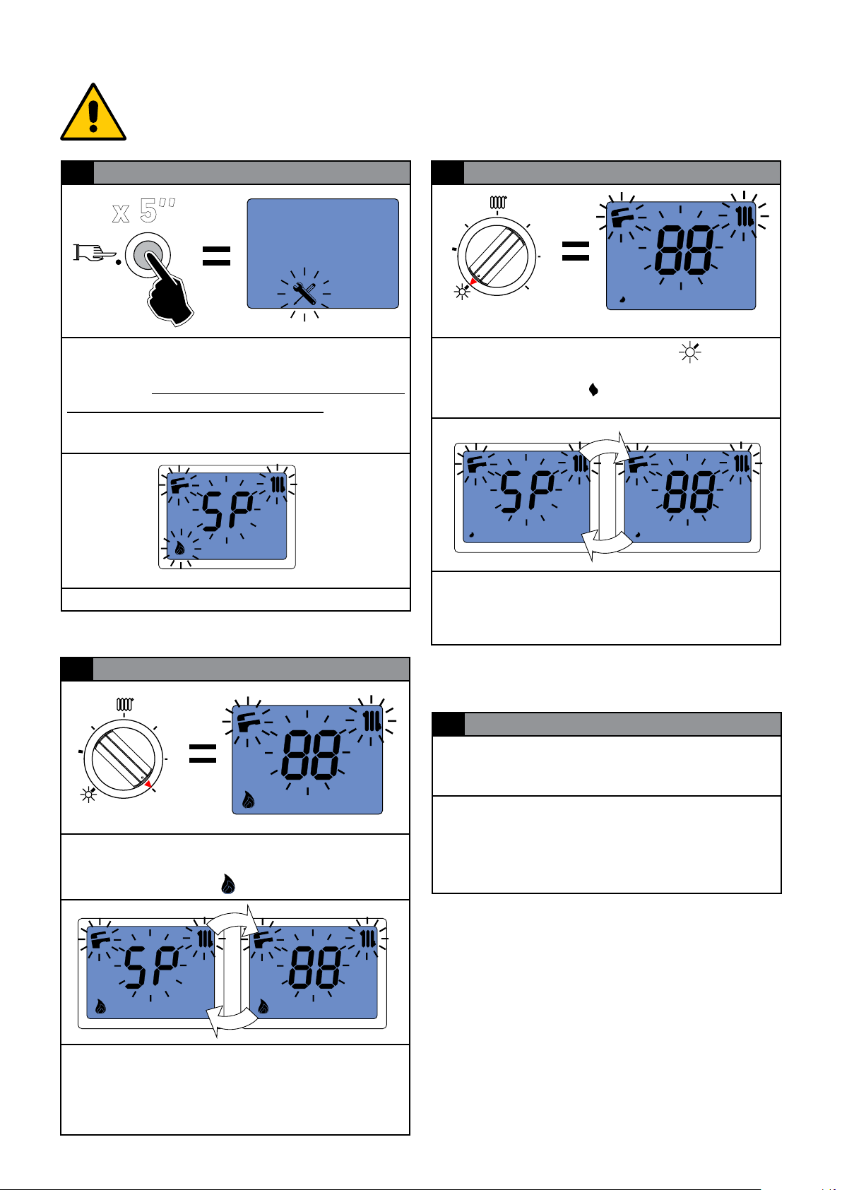
3.11 - MEASUREMENT OF COMBUSTION EFFICIENCY DURING INSTALLATION
x 5’’
3.11.1- ACTIVATION OF THE CALIBRATION FUNCTION
ATTENTION!
Function reserved for Authorised
Assistance Centres only.
The user is NOT authorised to activate
the function described below.
1 ACTIVATION
By pressing the button (D) for 5 seconds
SErvice appears,
Do not press it for more than
9’’ (par. 4.2) This function is not activated if there is
a block or domestic hot water request .It is possible to dispose of heat on the sanitary circuit by
opening 1 or more hot water taps.
all the symbols on the display ash
, until
3 MINIMUM OUTPUT
N
I
M
MAX
By turning the knob (B) in position , the boiler
will operate at minimum output:
- 1 lluminated symbol
and there is an alternation between SP and ow
temperature, the boiler operates at minimum
power.
Make combustion eciency
2 MAXIMUM OUTPUT
N
I
M
MAX
By turning the knob (B) onto MAX, the boiler will
operate at maximum output:
- 1 lluminated symbol
When the high ame symbol is xed on the display
and there is an alternation between SP and ow
temperature, the boiler operates at maximum
power.
Make combustion eciency
28
4 DISABLING
The “calibration” function stays active for 15 minutes.
To disable the CALIBRATION function before the
time elapses press the button (D) for 5 seconds
until the ‘SERVICE’ symbol appears
and then release. Do not press for more than
9 seconds.

1
2
3.11.2 - POSIZIONAMENTO DELLE SONDE
To determine the combustion eciency
one must make the following measurements:
- measurement of the combustion air temperature
taken in the relevant hole 1.
- measurement of the ue gas temperature and
content of CO2 taken in the relevant hole 2.
A
COXIAL PIPES
Air
probe
1
2
Take the measurements with the generator in
steady state conditions (see par. 3.11.1).
N.B.: Insert smoke probe only after
ignition of the burner, in order to avoid
the saturation of the analizer cells.
B
SEPARATE PIPE
1
ENGLISH
C
Air
probe
Flue gas
probe
PIPES Ø 80 TYPE B22
Air
probe
1
2
Flue gas probe
2
Installation Instructions
Flue gas probe
29

3.12 - ADJUSTING THE BURNER
Attention, during these operations do not take
any samples in domestic hot water mode.
All boilers leave the factory already calibrated and tested, however in the event
the gas valve recalibration is required:
- Loosen the needle screw ‘’P’’ located inside the
pressure socket at gas valve outlet and connect
a pressure gauge with reference to the gure.
- Check the supply pressure value (see NOZZLES
- PRESSURES table).
The following instructions are intended
exclusively for Unical AG Sp.A. authorised service personnel.
Reading value
Maximum / minimum pressure
1) Maximum output adjustment
- Operate the boiler in “calibration” mode at MAXI-
MUM OUTPUT (see 3.11.1).
- Once the burner is on check that the “MAXIMUM”
pressure value corresponds to that indicated in
the table “NOZZLES - PRESSURE”.
- Should it not correspond, correct it
(see calibration procedure Cap. 4.4)
2) Regolazione alla potenza minima
- Operate the boiler in “calibration” mode at MIN-
MUM OUTPUT (see 3.11.1)
- Once the burner is on check that the “MINIMUM”
pressure value corresponds to that indicated in
the table “NOZZLES - PRESSURE”.
- Should it not correspond, correct it
(see calibration procedure Cap. 4.4)
3) Conclusione delle tarature di base
- once the gas valve minimum and maximum pres-
sure values are checked
- disable the timed “calibration” function by switching
o the main switch.
- Remove the exible tube from the pressure
gauge and close the pressure socket screw
again.
- Check that there are no gas leaks.
30

36
35
34
33
32
31
30
29
28
27
26
25
24
23
22
21
20
19
18
17
16
15
14
13
12
11
10
10
20 30 40 50
60 70
80
90
99
0
NOZZLES - PRESSURE - COLLECTOR TABLE
Check the burner pressure levels especially at low ow rates.
The values in the table refer to a closed combustion chamber.
CoR R 24 - CoR C 24
Type of
Gas
Gas nat. (G20) 7,0 ÷ 23,8 7,5 ÷ 25,0 20 0,86 24 - 1,7 14,1 0,79 m³/h 2,64 m³/h
Propano (G31) 7,9 ÷ 23,8 8,5 ÷ 25,0 37 0,55 24 - 4,1 30,3 0,66 kg/h 1,94 kg/h
(*) ± 0,2 mbar range accettabile per G 20 (*) ± 0,2 mbar range accettabile per G31
3.12.1 - ADAPTATION OF THE POWER TO THE HEATING SYSTEM
Power
output
[kW]
ATTENTION!
Function reserved for Authorised
Assistance Centres only.
The user is NOT authorised to activate
the function described below.
Power
input
[kW]
Supply
Pressure
[mbar]
Ø
Nozzles
[mm]
Nozzles
no.
Ø Col-
lector
[mm]
kW
Pressure
minimum
[mbar]
Pressure
operating
[mbar]
Consumption
min.
Consumption
max.
ENGLISH
It is possible to adjust the maximum thermal capacity
in heating mode, by decreasing the burner pressure
value
Use the HP parameter (paragraph 4.2 SE parameter
list) to obtain the value corresponding to the desired
power.
Ex: CoR 24
to depower the boiler 20 kW,
modify parameter HP (about
70)
.
CoR 24
Installation Instructions
9
8
7
6
5
4
3
2
HP %
1
31

MAX
M
I
N
MAX
bar
service
I/L
G
N
F
M
O
MIN
4
INSPECTION AND
MAINTENANCE
Inspections and maintenance performed
professionally and according to a regular
schedule, as well as the use of original
spare parts, are of the utmost importance
for fault-free operation of the boiler and
to guarantee its long life.
Yearly maintenance of the appliance is
mandatory in compliance with Laws in
force.
4.1 - INSPECTION AND
MAINTENANCE INSTRUCTIONS
To assure long-term functioning of your appliance
and to avoid altering its approved status, only original
Unical spare parts must be used.
If a component needs to be replaced:
• Disconnect the appliance from the electrical mains
and make sure that it cannot be reconnected
accidentally.
• Close the gas shut-o valve upstream the boiler.
• If needed, and depending on the intervention to
be carried out, close any shut-o valves on the
ow and return line of the heating system, as well
as the cold water inlet valve.
• Remove the front casing from the appliance.
Failure to perform Inspections and Maintenance can entail material and personal
damage.
• Vent and, if necessary, restore the heating pressure until reaching a pressure of 0.8/1.0 bar.
• Open the gas shut-o valve.
• Switch the boiler on
• Make sure the appliance is gas tight and water-
tight.
• Remount the front casing of the appliance.
Once all maintenance operations are complete
resume boiler operation.
• Open the heating ow and return pipes, as well
as the cold water inlet valve (if closed previously).
TABLE OF RESISTANCE VALUES, ACCORDING TO THE TEMPERATURE, TO THE HEATING PROBE 11 (SR)
AND TO THE DOMESTIC HOT WATER PROBE 1 (SS) AND ANY HEATING RETURN PROBE 22 (SRR) see par. 4.5.
T°C 0 1 2 3 4 5 6 7 8 9
0 32755 31137 29607 28161 26795 25502 24278 23121 22025 20987
10 20003 19072 18189 17351 16557 15803 15088 14410 13765 13153
20 12571 12019 11493 10994 10519 10067 9636 9227 8837 8466
30 8112 7775 7454 7147 6855 6577 6311 6057 5815 5584
40 5363 5152 4951 4758 4574 4398 4230 4069 3915 3768
50 3627 3491 3362 3238 3119 3006 2897 2792 2692 2596
60 2504 2415 2330 2249 2171 2096 2023 1954 1888 1824
70 1762 1703 1646 1592 1539 1488 1440 1393 1348 1304
80 1263 1222 1183 1146 1110 1075 1042 1010 979 949
90 920 892 865 839 814 790 766 744 722 701
Relation between the temperature (°C) and the nom. resistance (Ohm) of the heating probe SR and of the domestic hot
water probe SS
Example: At 25°C, the nominal resistance is 10067 Ohm At 90°C,the nominal resistance is 920 Ohm
32

ROUTINE YEARLY VERIFICATION OPERATIONS
COMPONENT: VERIFY: CONTROL/INTERVENTION
METHOD:
FL
(domestic hot water
Is the minimum domestic hot water
ow rate 3 l/min.?
The burner must ignite with an
intake above or equal to: 3 l/min.
priority ow switch ( 2 )
VG
(Gas valve) ( 3 )
SR (heating sensor)( 11 )
SS (domestic hot water sensor)
( 1 )
SSR (return sensor) ( 22 )
E ACC/RIV. (ignition/detection
electrode) ( 4 )
TL (anti-overheating
limit thermostat) ( 10 )
DK (safety pressure switch
against water deciency) ( 13 )
Does the valve modulate properly? Open a hot water tap at maxi-
mum ow rate and then at minimum. Make sure that the ame
modulates.
Do the sensors maintain the
original characteristics?
Disconnect the sensor, place it
in the room, measure the resist-
ance value and, through the table Res / Temp (previous page),
check that it corresponds to the
room temperature measured by
a thermometer
Does the discharge of sparks before
putting the boiler in safe conditions last
less than 10 sec.?
Does the TL put the boiler in safety
conditions when overheating?
Does the pressure switch block the
boiler
if the water pressure is below 0.4 bar?
Detach the electrode ionisation
wire and check the securing
time.
Heat the TL until it intervenes
and check that it intervenes.
Without request: close the shuto valves of the heating circuit,
open the drain valve to make the
water pressure decrease. Before
pressurising again, check the
pressure of the expansion vessel.
ENGLISH
Expansion vessel ( 8 ) Does the vessel contain the right
amount
of air?
Check the pressure in expansion
vessel (1 bar when the boiler
is empty). Pressurise the boiler
(open the pump automatic vent
valve). Open the heating circuit
closing valves.
Condensation drain trap (26) Has the trap got deposits on the
Clean the trap with water.
bottom?
Domestic hot water ow rate Filter in cold water inlet ( 2 ) Clean the lter with limescale
remover.
Heat exchanger body (24 ) Check that the space between the
rungs of the exchanger are not clogged
Eliminate the deposits without
damaging the exchanger, using
a soft bristle brush and specic,
non ammable detergents.
Burner ( 28 ) Check the state of cleanliness of the
burner mesh
Remove any deposits using
compressed air, blowing from
the mesh side.
( Num ) = see key Par. 2.2
Installation Instructions
33

4.2 - PARAMETERS THAT CAN BE EDITED FROM THE CONTROL PANEL
ATTENTION!
Function reserved for Authorised Assistance Centres only.
Menu access:
InF InFormation
Hi Errors Log
SE SErvice
FA Factory
tA tAratura _CALIBRATION
1 ACTIVATION - SELECTION
DISPLAY
2
Turn knob (B) to display the parameter list InF
PARAMETERS LIST InF
Press reset buton (D) for 10 sec. then release
(service ashing)
Turn knob (B)
service
service
to scroll through the menu’
service
service
service
The display alternates the Parameter and Value
CODE DESCRIPTION
FS
oS
dS
rS
dt
ICH
FP
Heating temperature, - - if the heating sensor is faulty
External temperature, - - if there is
no external probe or if it is faulty
Domestic hot water temperature, - - if
there is no sensor or if it is faulty
Return temperature, - - if there is no
auxiliary sensor or if it is faulty
Dierential ∆t between ow and
return.
Heating temperature calculated,
(been ‘‘room zone’’ ON-OFF and
‘‘remote zone’’ OT+.)
Air Fan signal pressure
(Pa)
INFORMATION
Press reset (D) to access the Inf parameters unit
34
PH
Sr
Sd
Io
Water pressure, is there is not pressure sensor, - - is displayed
Firmware version (Factory)
Firmware version (Servicing)
Ionization Current (µA)

(Hi) Errors Log
x 10’’
ATTIVAZIONE - SELEZIONE Vedi punto 1 (4.2)
Premere il tasto (D) per accedere al gruppo
parametri Hi,
3
DISPLAY - FAULT
Press reset button (D) to display the fault code
(see chap.5).
ENGLISH
The display alternates H and the number of the
position (01) in which the error is stored.
2
DISPLAY
Turn knob (B) to display the sequence of faults
between 01 ÷ 12
PARAMETERS LIST (Hi) Errors Log
Position Description
01
02
last error displayed
penultimate error displayed
01 = last error
displayed
4
EDIT VALUE - RESET
08 = fault code (LP
Water deciency)
ref. chap. 4.6
D
Enter the error string H01 keep press reset (D) until
the display shows INF,
This operation must only be performed in the
event one wants to delete the log completely (for
example, if important updates are made it may
therefore be useful to have a new chronological
reference of events).
o reset the whole errors log.
Installation Instructions
03
04
05
06
07
08
09
10
11
12
last but two error displayed
................error displayed
................error displayed.
................error displayed.
................error displayed.
............... error displayed
............... error displayed
third error displayed
second error displayed
rst error displayed
5
DISABLING
Briey (2 ÷ 5 sec.) press the key (D) to go back to
the main menu See section 1 (4.2), or press it for
over 5 seconds to exit.
35

(SE) Service parameters
ACTIVATION - SELECTION See section 1 (4.2)
Press reset buton (D) to access the SE parame-
ters unit. These parameters can be edited without restrictions, from the control panel.
2
DISPLAY
EDITING THE VALUE
3
Press reset buton (D) to access the parameter,
the parameter value ashes.
Correct the value with knob (C)
(Counterclockwise - Clockwise)
4
4 CONFIRM VALUE
Turn knob (B) to display the parameters list
PARAMETERS LIST SE
CODE RANGE DESCRIPTION
Post circulation
Po
oC
nr
PH
HP
HL
HH
dL
dH
0 1
-20 10
0 30
0/5 30
0 1
0 100
20 50
50 85
25 45
50 65
0 = post 5’’ (default)
1 = continuous
External probe on panel
- 20÷10 °C
External probe on Regolafacile
0 = - 20 °C
30 = +10 °C (default 10)
Night reduction
0 = T.A. (default)
5 ÷ 30 = night reduction
Domestic hot water preheat function
0 = Not active (default)
1 = Active
Maximum heating modula-
tion level (default 100)
Minimum heating set point
level (default 30)
Maximum heating set point
level (default 85)
Minimum domestic hot water
set point level (default 35)
Maximum domestic hot water
set point level (default 60)
(default -10)
Press key D
36

(FA) Factory Parameters
D
service
ACTIVATION - SELECTION See section 1 (4.2)
Press rest button (D) to access the FA param-
eters unit. These parameters can be edited by
entering the ACCESS CODE.
2
ACCESS CODE
UNIT 1 - FA PARAMETERS LIST
CODE RANGE DESCRIPTION
Type of Gas
Gt
PL
Pr
dt
SP
AP
PS
PA
0 1
15 100
20 100
5 20
0 6
1 4
0 1
15 60
0 = methane (default)
1 = GPL
Minimum pump modulation
level *
Maximum pump modula-
tion level
Pump temperature dier-
ential
Pump pause time during
CH / DHW service change
and vice-versa
0 = no pause
1÷6 = Time in seconds
1: Instantaneous boiler
2: Instantaneous boilers
with
3: Heat. only boiler / or
storage tank (1 pump +
1 3-way val.)
4: Boiler with storage tank
2 pumps
Heat. pressure sensor
0 = absent / 1 = present
(default 0)
Ignition air pressure
(default 30)
xed hysteresis
ENGLISH
Use knobs to dial the code (B - TENS) - (C UNITS)
Conrm with the reset button (D)
Once the access code has been entered, Fac-
tory parameter units are displayed
DISPLAY
3
Turn knob (B) to scroll the parameters.
oA
rP
bP
AL
Hr
hP
hl
hd
dP
dl
dd
0 60
0 1
1 9
0 1
0 10
1 20
1 20
1 20
1 20
1 50
1 20
Oset Air (default 20)
Primary Dt protection
0 = disabled
1 = enabled
(default 1)
Type boiler / Power
(befault 1)
Function antilegionella
storage tank boiler (w3/W4)
Mantenimento richiesta
sanitaria
Heating control:
proportional
Heating control:
integrative
Heating control:
derivative
Domestic hot water
control: proportional
Domestic hot water
control: integrative
Domestic hot water
control: derivative
Installation Instructions
37

SL
tt
3 90
0 20
Ramp time CH
(Value *10) = sec
Adjustment code
(default 0)
- manual (set = 0)
- automatic (set = 5)
4.3 - ADAPTATION
TO THE USE OF OTHER GAS
The boilers are produced for the type of gas specically requested upon ordering.
DANGER!
The conversion for the operation of
the boiler with a type of gas other
than that specically required in the
order, must be performed by Unical
professionally qualied personnel, in
compliance with the standards and
regulations in force.
The manufacturer cannot be held
liable for any damage resulting from
a conversion operation that is incorrect or not performed in compliance
with the laws in force and/or with the
instructions given.
ATTENTION!
After performing the conversion for
the operation of the boiler with a type
of gas (e.g. propane gas) other than
that specically requested when ordering, the appliance will only work
with this new type of gas.
ATTENTION!
Indications for propane gas-fired
appliances
Make sure that the gas tank has been
deaerated before installing the appliance.
For state-of-the-art deaeration of the
tank, contact the LPG supplier or a
person qualied in compliance with
law.
If the tank has not been professionally
deaerated, ignition problems could
arise.
In that case, contact the supplier of
the LPG tank
To convert the boiler from one type of gas to
another, proceed as follows:
- Disconnect the appliance from the elctrical power
supply
- Remove the screw (1) that join the burner pack
(2) to the nozzle manifold (3)
- Disconnect the gas pipe above the gas valve.
- Extract the nozzle manifold (3) and replace it with
the one contained in the gas conversion kit.
- Once the manifold has been replaced, re_mount
it all andg ive the power supply.
38

Modify parameter FActory:
posizione
conferma
PARAMETER FA par 4.2
CODE METHAN PROPAN
formation required on the label supplied in the
documentation envelope and apply it next to the
technical data label of the boiler.
Gt
0 1
Once the Gt parameter has been edited
one must perform the AUTOmatic calibration (change parameter tt)
PARAMETER FA par 4.2
TARATURA - ADJUSTMENT
CODE MANUal AUTOmatic
tt
0 5
- Perform calibration AUTOmatic cap. 4.4.1.
- when the conversion is complete, ll in the in-
4.4 - ADJUSTMENT _TARATURA tA
The Gas Valve does not provide mechanical calibration; the minimum and maximum power settings are
then electronically performed through two parameters
(visible and modiable during calibration):
EXAMPLE OF COMPILATION
ENGLISH
- P0 absolute minimum power; range 0 ÷ 100
- P1 absolute maximum power; range 0 ÷ 100
There are two calibration methods:
- “Manu” allows an adjustment of the values around
the calibrated value (approximately +/- 1.5 mbar).
It is activated with the procedure described in
section 4.4.1 (recommended procedure in most
cases).
- “Auto” allow reset of the previous values and the
complete calibration of the gas valve (typical use
in case of valve replacement or gas transformation). It is activated with the procedure shown
in section 4.4.2
Function / description of knobs and ‘’ D ‘’ key in calibration function
per memorizzare
N
I
M
position to
decrease
value
MAX
MIN
position
to set
the value
il valore
MAX
Installation Instructions
position to
inecrease
value
tasto di
/
scelta
button of
conrmation /
choice
P0
potenza
minima
minimum
power
P1
potenza
massima
maximum
power
posizione per
diminuire
il valore
posizione per
aumentare
il valore
39

x 10’’
+-
+-
4.4.1 - ADJUSTMENT TARATURA MAnu
Pressure MAX P1
N
I
M
MIN
MAX
Without heat requests, place knobs “B” and “C” to max.
Press buton “D” for more 10 sec. and then release ( “SERVICE” ashes).
MAX
service
x 3’’
service
service
service
13.5
Press the ‘’D‘’ key for 3 sec. and Manu scrolling writing appears, the burner works at MAX and appears
P1 on display press the ‘’D‘’ key to display the value (eg. 76).
Read the pressure value MAX on the pressure gauge and compare it with the value in the table NOZZLES
PRESSURE Chap. 4.2 (for example, 14.1).
Considering the example shown in the gure, having to calibrate the valve to 14.1 mbar it can be concluded
that it is a VALUE TOO LOW therefore:
++
14.1
=
MIN
MAX
service
40
Turn the ‘’C‘’ knob to the MAX and press the ‘’D‘’ button more time until it is close to the desired value
(eg. 82 red on display, which corresponds to 14.1 read on the pressure gauge).
NOTE: do not exceed the target of (max + 0,2 mbar) and carry out the adjustment in RISE (the valve
gas works better with ever increasing correction).
If the value read on the pressure gauge (eg 14.1) is satisfactory,
x 2’’
service
MIN
MAX
SET:
Turn the ‘’C‘’ knob to the INTERMEDIATE position and press the ‘’D‘’ button for about 2 seconds
(the new value will ash indicating new storage).

+-
+-
Pressure MIN P0
N
I
M
ENGLISH
1.2
MAX
MIN
service
MAX
service
Turn knob B to MIN, the display will show P0 and the modulation will drop to the minimum preset.
Wait few seconds for the pressure value to stabilize. Read the pressure value MIN on the pressure gauge
and compare it with the value in the table NOZZLES PRESSURE Chap. 4.2 (eg 1.2).
Considering the example shown in the gure, having to calibrate the valve at 1.7 mbar can be concluded
that this is a VALUE TOO LOW therefore:
++
1.7
=
MIN
MAX
Turn the ‘’C‘’ knob to the MAX and press the ‘’D‘’ button more time until it is close to the desired value
(eg. 72 red on display, which corresponds to 14.1 read on the pressure gauge).
If the value read on the pressure gauge (eg 1.7) is satisfactory,
service
Installation Instructions
x 2’’
service
MIN
SET:
Turn the ‘’C‘’ knob to the INTERMEDIATE position and press the ‘’D‘’ button for about 2 seconds
(the new value will ash indicating new storage).
MAX
41

+-
4.4.2 - ADJUSTMENT - TARATURA Auto
Pressure MAX P1
Enter in FActory parameter to change parameter tt
(see section 4.2, the access code is required, page
37).
PARAMETER FA par 4.2
ADJUSTMENT - TARATURA
CODE MANUal AUTOmatic
tt
service
N
I
M
service service
MAX
MIN
0 5
MAX
Enter the FA parameters, after access code,
turn knob “B” to max until “tt” parameter is reached, press button “D”, modify
the value 00 in 05 by means of the “C” knob and then conrm by pressing the “D” button.
service
x 3’’
service
Press the “D” button for about 3“; “tA” menu will appear again.
Activate the calibration function by pressing the “D” button for about 3“;
x 3’’
service
service
service
5.6
the writing “Au to” will appear, the burner works at MAX and appears on the display P1 press the ‘’D‘’
key to display the value (eg 31).
Read the pressure value MAX on the pressure gauge and compare it with the value in the table NOZZLES
PRESSURE Chap. 4.2. (ed. 14.1). Considering the example shown in the gure, having to calibrate the
valve to 14.1 mbar it can be concluded that it is a VALUE TOO LOW therefore:
42

++
+-
+-
14.1
=
MIN
MAX
service
Turn the ‘’C‘’ knob to the MAX and press the ‘’D‘’ button more time until it is close to the desired value
(eg. 82 red on display, which corresponds to 14.1 read on the pressure gauge).
NOTE: do not exceed the target of (max + 0,2 mbar) and carry out the adjustment in RISE (the valve
gas works better with ever increasing correction).
If the value read on the pressure gauge (eg 14.1) is satisfactory,
x 2’’
service
MIN
MAX
ENGLISH
SET:
Turn the ‘’C‘’ knob to the INTERMEDIATE position and press the ‘’D‘’ button for about 2 seconds
(the new value will ash indicating new storage).
Pressure MIN P0
N
I
M
MAX
MIN
service
MAX
service
Installation Instructions
6.0
Turn knob B to MIN, the display will show P0 and the modulation will drop to the minimum preset.
Wait few seconds for the pressure value to stabilize. Read the pressure value MIN on the pressure gauge
and compare it with the value in the table NOZZLES PRESSURE Chap. 4.2 (eg 1.2).
Considering the example shown in the gure, having to calibrate the valve at 1.7 mbar can be concluded
that this is a VALUE TOO LOW therefore:
43

++
+-
1.7
=
service
Press button ‘‘D’’ more time until it is close to the desired value
(eg. 70 red on display, which corresponds to 1.7 read on the pressure gauge).
If the value read on the pressure gauge (eg 1.7) is satisfactory
x 2’’
MIN
MAX
service
SET:
Turn the ‘’C‘’ knob to the INTERMEDIATE position and press the ‘’D‘’ button for about 2 seconds
(the new value will ash indicating new storage).
N.B. It is important to proceed rst with the calibration of the maximum and completed with the
minimum calibration. Eventually, at the end of the minimum calibration, it will be possible to perform
a check by moving back to the maximum level using knob “B”.
- To exit, disconnect the power supply.
- Close any domestic hot water tap
- Disconnect the pressure gauge and close the pressure relief of the Gas Valve well.
44

(GND)
(OUT)
(IN)
+-
R
SE
BK
TA 1/OT TA 2
WH
WH
Y
Y
BK
BK
G
ND
WH
SL
BK
CASING
E. ACC./RIL.
T.ACC
A7
12A52143 65
A8
21 43 5
A9
4
3
2 1
A1
12
3
4
5
678
9
A2
1
2
3
4
5
67
4
3
21
A4
1
2
3
A3
2
3
1
5
6
4
MVD
P
N
L1
BR
YG
BL
1
2
3
BL
BR
BK
(CH)
(DHW)
M
230 V
50 Hz
L
1
N
G
ND
YG
BL
BR
V
N
L1
BR
YG
BL
A3
2
3
1
5
6
4
M1
CMP
2
1
GR
MODULAT
.
(+12 V) NOT USED
PK
A4
1
2
3
1
2
3
4
5
67
A2
COMNO
BL
BL
WH
BR
G
G
SRRDKTL (1/2)
BL
A1
12
3
4
5
678
9
TDPA FLS SS SR
WH
WH
R
R
WH
BR
R
BR
BK
4
3
21
A6
EV2
EV1
(Mod)
(On/Off)
+-+-
VG
V
WH
R
OR
A6
A8
1
2
3 4 5
4.5 - WIRING DIAGRAM Practical connection board
ENGLISH
Installation Instructions
KEY
A1.....A9 Services connectors
CMP Modulating pump control
DK Waterdeciencysafetypressureswitch
E.ACC./RIL Ignition/detection electrode
FLS Domestichotwaterrequestowswitch
MVD Diverter valve motor
P Pump
SL Condensate level sensor
SR Flowheatingsensor
SRR Returnheatingsensor
SS
TDPA Air pressure transducer
TL 1_2 Safetythermostat1and2
Domestichotwaterprobe(Pred.forRmodels)
VG Gas valve
V Modulating fan
SE Externalprobeconnectionterminals
TA1 / OT Modulating TA connection terminals
TA2 On/off TA connection terminals
45

4.6 - ERROR CODES
Thesymbolashesonthedisplaymonitorwhentheboilerdetectsananomaly.
1)Intheeventofananomalythatdoesnotstopboileroperation,presskey‘‘D’’to
displaytheerrorcode;intheeventtheboilerisinstand-by,theerrorcodeappears
andremainsxedonthedisplay.
2)Intheevent ofananomalythatcausesboilerdowntime,the errorcodeashes
directlyonthedisplay.
Eachfaultischaracterisedbyaprioritylevel:iftwofaultsaredetectedatthesame
time,thecodewiththehighestpriorityisdisplayed.Thefaultcodesarelistedbelow:
F)Faultcodedisplayedwithcodenumber:
ThedisplayashesalternatingtheF(FAULT-ANOMALY)witherrorcode(eg23).
SYMBOL PRIO-
COD.REGO-
LA FACILE/
STORICO
ERRORI
RITY
09 0 EXTERNAL PROBE
( Num ) = see key Par. 2.2
DESCRIPTION SOLUTIONS
Check the wiring, if needed
interrupted
replace the external probe
14 1
RETURN PROBE
Auxiliary (SRR) sensor interrupted
45 2
WATER OVERPRESSURE
detected if the H2O pressure
Transducer is present with
pressure > 2.5 bar; it is reset
automatically when H2O pressure < 2 bar
30 3 SERVICE PARAMETERS
Service parameters altered due
to possible electromagnetic
interferences.
21 4 POOR WATER CIRCULATION
Poor circulation in primary
circuit
17 5 FLAME CONTROL FRE-
QUENCY BEYOND LIMIT
Depends on the power supply
mains (Frequency and voltage
beyond default limits)
15 6 WATER CIRCULATION IN-
SUFFICIENT
Primary circuit water circulation
insucient (∆t > 35° C)
22 7 INCORRECT SENSOR PO-
SITIONING Flow and return
sensors inverted
24 8 SPEED OUT OF
CONTROL
Alteration of the fan speed; the
speed is not reached.
Check the wiring, if needed replace the auxiliary sensor (22)
Wait for the values to return to
default limits /
Replace the Transducer
Reset the altered parameters
via the panel and/or regolafacile
Check pump operation (12)
and speed, if there are any
obstructions or system closure.
Wait for the values to return to
the default limits
Check pump operation (12)
and speed - remove any heating system obstructions - clean
the scaled domestic hot water
exchanger
Check the wiring (21) (22)
Check fan operation (18) and
the connections
46

26 9 SPEED OUT OF
CONTROL
Alteration of the fan speed; the
speed is above that requested
Check fan operation (18) and
the connections
6 10 HIGH TEMPERATURE
Boiler temperature too high
8
NO
WATER
11 WATER DEFICIENCY
Insucient water pressure and
consequent intervention of the
minimum water pressure - pressure switch ( 13 ).
44
NO
WATER
12
WATER PRESSURE
detected if the pressure Transducer is present
16 13 EXCHANGER
FREEZING ( 24 )
Exchanger freezing is detected
If the heating sensor detects a
temperature below 2° C, burner ignition is inhibited until the
sensor detects a temperature
above 5°C.
13 14
DOMESTIC HOT WATER SENSOR
Domestic hot water sensor
fault (1)
12 15 HEATING SENSOR (11)
Heating sensor fault
Check pump operation and if
needed
clean the exchanger (24)
Fill the heating circuit as described in chap. 3.8 and wait
for the values to return within
default limits.
If needed, check the electrical connections and replace
the minimum water pressure
switch.
Wait for the values to return
to default limits / Replace the
Transducer
Disconnect the from the
power supply, close the gas
valve, defrost the exchanger
carefully.
Check the efficiency of the
sensor (see table Res/Temp)
(Par.4) or its connections.
Check the efficiency of the
sensor (see table Res/Temp)
(Par.4) or its connections.
ENGLISH
38 16 FACTORY PARAMETERS
Alteration of the factory parameters due to possible electromagnetic interferences.
1
LIMIT
THERM
4
BLOCK
17
SAFETY THERMOSTAT
Intervention of the safety thermostat (10)
18 BLOCK
No gas or failed burner ignition
Press the unblock key; if the
anomaly persists, replace the
board.
Installation Instructions
Press the unblock button on
the panel and/or check that the
thermostat or its connections
are not interrupted.
Check the gas supply or that
the ignition/detection electrode
is working properly (4).
47

service
11 19 PARASITE FLAME
Flame detected upon ignition
20 20 FIAMMA PARASSITA
Fiamma rilevata dopo lo spegnimento
(F) 27 22
ERROR
Flow Gradient
Check the wiring of the Ign/Det.
electrode and remove any oxidation.
Check for humidity between drain wire
and ceramic, if necessary, replace
the electrode, press the unblock key,
if the anomaly persists, replace the
electrode (4).
Vericare il cablaggio ed eventuali perdite della valvola gas
(3) event. sostituire Valv. gas.
Check if the pump switches o
suddenly.
(F) 23 23
Detected tab panel button pressed for longer than 30 “
Check keypad and reset the
status of the buttons. Or replace the electronic board
(F) 53 24
service
service
BLOCK 28
service
service
service
BLOCK 32
Clogged Outlets Check the Chimneys / Check
the trap.
Control circuit problems
Gas Valve
Gas Valve opening time beyond
limit time
Check the Gas Valve connections / Replace the Gas Valve
(3) / Replace the Modulation
Board
Check the parts that generate
the heat requests (thermostats,
electrovalve limit switches, ow
switch, etc.)
89
service
BLOCK
Flame loss Check the electrode and its wi-
General block for unclassied
anomalies.
ERRORS DISPLAYED ON REGOLAFACILE ONLY
- 75 -
- 80 -
- 81 -
48
Regolafacile external sensor Replace the external probe /
Regolafacile Internal Sensor Replace Regolafacile
Eprom Error of Regolafacile Replace Regolafacile
ring to check the gas pressure
at minimum power, if necessary re-calibrate.
Replace Modulation Board.
Regolafacile

ENGLISH
Installation Instructions
49

50

51

www.unical.eu
st
ed. 12/18
ORIGINAL INSTRUCTIONS - 00337853EN - 1
46033 casteldario - mantova - italia - tel. +39 0376 57001 - fax +39 0376 660556
Also reserves the right to bring those changes that it will hold necessary to it own products or prots, without jeopardizing its essential characteristics.
AG S.p.A.
info@unical-ag.com - export@unical-ag.com - www.unical.eu
Unical declines every responsibility for the possible inaccuracies if owed to errors of transcript or press.
 Loading...