

Unical Alkon 09 R 18, Alkon 09 C 18, Alkon 09 R 24, Alkon 09 C 24 User Operating Instructions Manual
Page 1

00333177 -1st edition - 06/2009
ALKON
09
R 18 - C 18
R 24 - C 24
USER’S OPERATING
INSTRUCTIONS
Page 2

2
Contents
1 - SYMBOLS USED IN THIS GUIDE
When reading this guide particular care has to be given to the parts marked with the followings symbols:
NOTE!
Suggestions for the user
WARNING!
Indicates a potentially dangerous
situation for the product and the
environment
DANGER!
Indicates serious danger
for your personal safety
and for your life
2 - CORRECT USE OF THE APPLIANCE
The ALKON appliance has been designed utilizing today’s heating technology and in compliance with the
current safety regulations.
However, following an improper use, dangers could arise for the safety and life of the user or of other
people, or damage could be caused to the appliance or other objects.
The appliance is designed to be used in pumped hot water central heating systems and for domestic hot
water production.
Any other use of this appliance will be considered improper.
UNICAL declines any responsibility for any damages or injuries caused by an improper use; in this case the
risk is completely at the user’s responsibility.
In order to use the appliance according to the scopes it was designed for it is essential to carefully follow
the instructions indicated in this guide.
3 - WATER TREATMENT
• The hardness of the mains water supply conditions the frequency with which the heat exchanger is cleaned.
• In hard water areas where the main water can exceed 15°f total hardness, a scale reducing device is recommended. The choice of this device has to be made taking into consideration the water’s characteristics.
• In order to improve the resistance to lime scale, it is recommended to adjust the domestic hot water temperature as near as possible to the one you really require.
• The use of a modulating room thermostat reduces the dangers of lime scale formation.
• We recommend you to check the state of cleanliness of the domestic hot water heat exchanger at the end of the
first year and subsequently, on the basis of the amount of lime scale found, this period can be extended to two
years.
CONTENTS
1 Symbols used in this guide ....................................................................................................................................................... 2
2 Correct use of the appliance .................................................................................................................................................... 2
3
Water treatment ......................................................................................................................................................................... 2
4
Information to be handed over to the user ............................................................................................................................... 3
5 Safety warnings ......................................................................................................................................................................... 3
6 Operating instructions ............................................................................................................................................................... 4
6.1 Control panel ...................................................................................................................................................................... 4
6.2 Check list before commissioning the boiler ...................................................................................................................... 6
6.3 Boiler operation .................................................................................................................................................................. 6
DHW production ................................................................................................................................................................ 6
CH Mode ............................................................................................................................................................................ 6
Shutting down the boiler .................................................................................................................................................... 6
6.4 Frost protection mode ........................................................................................................................................................ 6
6.5 Eliminating the faults .......................................................................................................................................................... 7
Page 3

3
General information
The user has to be instructed on the use and operation of his heating system, in particular:
• Hand over these instructions to the end user, together with any other literature regarding this appliance, placed
inside the envelope contained in the packaging. The user has to keep these documents in a safe place in
order to always have them at hand for future reference.
• Inform the user on the importance of air vents and of the flue outlet system, stressing the fact that is absolutely
forbidden to make any alterations to the boiler.
• Inform the user how to check the system’s water pressure as well as informing him how to restore the correct
pressure.
• Explain the function of time and temperature controls, thermostats, heating controls and radiators, to ensure
the greatest possible fuel economy.
• Remind the user that, in order to comply to the standards in force, it is necessary to inspect and service the
boiler according to the current codes of practice and according to the schedule indicated in this manual by the
manufacturer.
• If the appliance is sold or transferred to another owner or if the present user moves home and leaves the
appliance installed, ensure yourself that the manual always follows the appliance so that it can be consulted
by the new owner and/or installer.
Failure to follow the instructions indicated in this guide, which is supplied with the boiler, could cause injury
to persons, animals or damage to property. The manufacturer shall not be held liable for any such injury and/
or damage.
4 - INFORMATION TO BE HANDED OVER TO THE USER (BY THE INSTALLER)
5 - SAFETY WARNINGS
WARNING!
The installation, adjustment, and servicing of this appliance must be carried out by a competent person and
installed in accordance with the current standards and regulations. Failure to correctly install this appliance could cause injury to persons, animals or damage to property. The manufacturer shall not be held liable
for any such injury and/or damage.
DANGER!
NEVER try to service or repair the appliance yourself.
All types of servicing or repairs must be carried out by a professionally qualified person, authorized by
UNICAL; UNICAL recommends drawing up a service contract.
Bad or irregular servicing could compromise the safe operation of the appliance, and could cause injury to
persons, animals or damage to property for which UNICAL shall not be held liable.
Alterations to parts connected to the appliance
Do not carry out any alterations to the following parts:
- the boiler
- to the gas, air, water feed pipes and electrical current
- to the flue pipe, safety relief valve and its drainage pipe
- to the constructive components which influence the appliance’s safe operation
Smell of gas
If you smell gas follow these safety indications:
- Do not touch any electrical switches
- Do no smoke
- Do not use the telephone
- Close the On/Off gas service cock
- Open all windows and doors where the gas leakage has occurred
- Inform the gas society or a specialized company
Explosive and easily inflammable substances
Do not use or leave explosive or easily inflammable material (as for example: petrol, paint, paper) in the room
where the appliance has been installed.
Page 4

4
User’s operating instructions
A = Manometer
B = Summer/Winter switch + Heating temperature controller
C = D.H.W. temperature controller
D = Push button for RESET/CALIBRATION/DIAGNOSTICS
E = Display
F = Symbol indicating a heating request
G = Symbol indicating a D.H.W. request
I = Symbol indicating a burner lockout
L = Symbol indicating burner in operation
M = Symbol indicating an error presence
N = Digits indicating boiler temperature or error code
B
D ACE
F
G
L
I
M
N
Summer/Winter switch + Heating temperature
controller
Through this knob it is possible to select the
operation mode:
· Summer (D.H.W. production only)
· Winter (Heating and D.H.W. production)
The pointer of the knob in
Summer
position
means that the boiler does not supply any
heating (in any case the anti-frost protection
remains active).
With the pointer of the knob within the range
shown beside, the boiler is in Winter mode
and controls the heating water temperature,
which can be adjusted between a minimum
of 30°C and a maximum of 85°C.
D.H.W temperature controller
In the ALKON R models this function is active only if the boiler
is connected to an external D.H.W. storage tank.
Through this knob it is possible to adjust the
temperature of the D.H.W.
NOTE
In the ALKON R models, not
connected to an external
D.H.W. storage tank, the
pointer of the knob has to be
positioned as shown beside.
With the pointer of the knob within the range
shown beside, the D.H.W. temperature is 38°C.
Function “ECO-COMFORT”
With the pointer of the knob within the range
shown beside, there is the activation of the
function ECO-COMFORT, which assures a
drawing of D.H.W. at 38°C with the best energy
saving.
Function “COMFORT”
The D.H.W. temperature can be adjusted
between a minimum of 38°C and a maximum
of 60°C.
HOLIDAYS
If the boiler is not controlled by a modulating
chrono-thermostat, during Holidays period the
pointer of the knob has to be positioned within
the range shown beside.
°C
®
MAX MAX
M
I
N
MAX
MAX
MAX
MAX
MAX
MAX
6 - OPERATING INSTRUCTIONS
6.1 - CONTROL PANEL
Page 5

5
User’s operating instructions
Operation in Heating mode
The symbol is shown when the boiler receives a
heat request for C.H. If, at the same time, there is
a heat request also for D.H.W. production this
symbol is switched off.
Operation in D.H.W. mode
The symbol is shown when the boiler receives a
heat request for D.H.W. production
Burner Lockout indication
This symbol is shown when the burner is put in
lockout by the burner control, due to:
· Lack of gas
· Lack of ignition
In the first case, in which none ignition took place,
ascertain the gas cock is open.
Fault indication
This symbol is shown when there is a fault within
the boiler.
1) If the fault does not cause the stop of the
boiler operation, to have the error code shown
on the display, it is necessary to press the reset
button (D); in case the boiler is in stand-by the
error code is shown also without pressing the
reset button.
2) If the fault causes the stop of the boiler
operation, the error code is shown flashing on
the display.
Reset button
By pressing this push button, it is possible:
· To restart the boiler after a lockout due to the
burner control, which has lit, on the display, the symbol
.
· To have the error code shown on the display if
the boiler operation was not stopped by this fault.
· To activate the special function for calibration.
· To enter the Service Menu and select the
parameters.
Indication of burner in operation
This symbol indicates the burner is in operation.
The symbol is shown when the boiler receives a
heat request for C.H. or D.H.W. production.
Thermometer
It shows the boiler or the DHW temperature.
If, on the display, the symbol
( ), is
shown,
the temperature is the one of the heating
circuit.
If, on the display, the symbol
( ) is
shown,
the temperature is the one of the DHW
circuit.
Manometer
It shows the water pressure
of the heating circuit; the value of
such pressure has to be equal or higher than
0,8/1 bar(in cold conditions).
If the pressure is below
0,8/1 bar the boiler operation is inhibited and
it is necessary to restore
the correct value acting on the filling cock.
This operation has to be performed when the
heating circuit is cold.
Page 6
6
User’s operating instructions
6.4 - FROST PROTECTION MODE
The boiler is fitted with a frost protection system which will
operate automatically when the system temperature falls below 6°C: the burner is automatically fired and the pump is
energized until the system’s water temperature has risen to
16°C.
If the temperature detected by the CH sensor falls below 2°C,
burner operation is automatically stopped until the temperature has risen to 5°C.
D.H.W. production (Summer mode)
Make sure the selector (B) is in position ( )
Position the D.H.W. temperature adjusting
knob (C) on the desired temperature:
COMFORT between 38 and 60°C, ECOCOMFORT or ECO.
Note:
By adjusting the DHW temperature at a temperature very close to the one actually used
will avoid mixing hot water with cold water,
thus resulting in fuel savings and a significant reduction of lime scale formation.
When opening a D.H.W. tap the boiler will start automatically
in order to supply water at the desired temperature.
During all the phase of D.H.W. drawing,
on the display the actual D.H.W.
temperature and the symbol (
) are
shown.
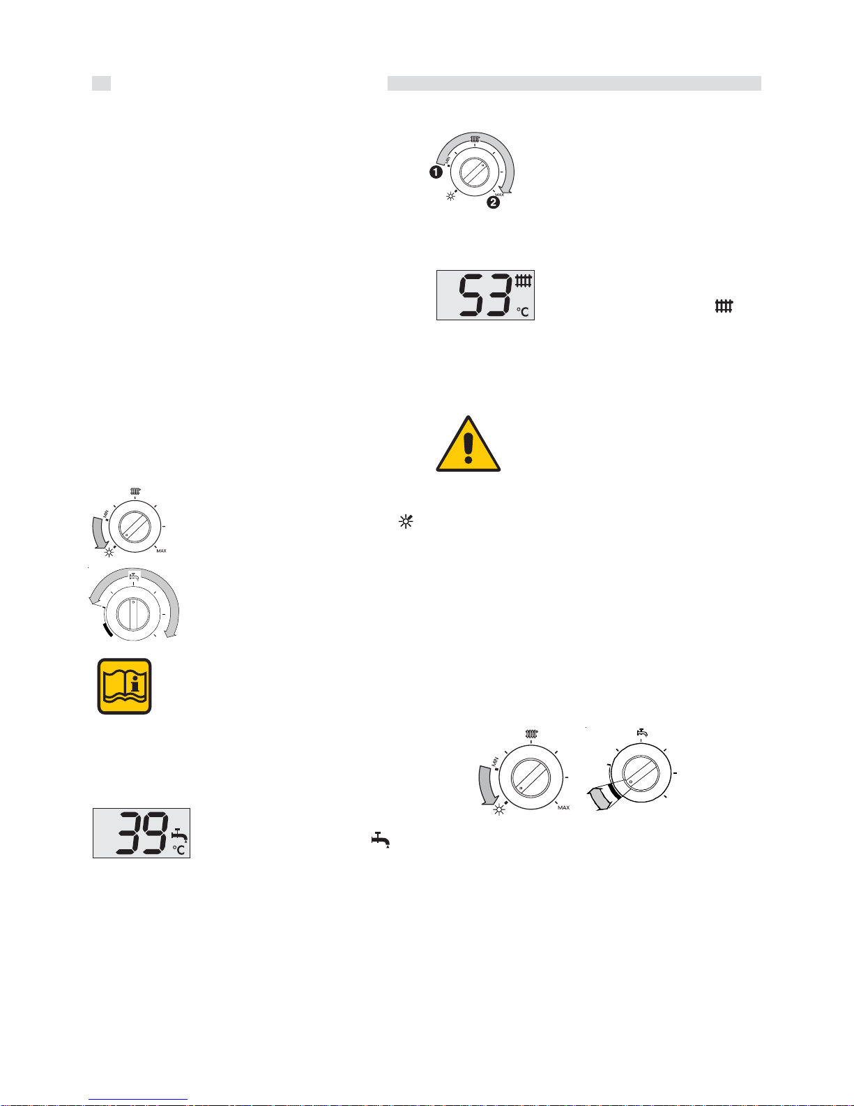
C.H. mode (Winter mode)
In order to have the boiler operating for C.H.
purposes, the pointer of the knob (B) has to
be positioned between 1 (minimum
temperature) and 2 (maximum
temperature).
If the C.H. installation is equipped with a Room thermostat,
position the pointer of the knob (B) in an intermediate position.
During the operation in C.H. mode, on
the display the actual boiler water
temperature and the symbol ( ) are
shown.
Put out of operation
In order to put completely out of operation the boiler cut the
power supply to the boiler through the external main switch.
In case of long periods of inactive state of the
boiler close also the gas and cold water cocks.
B
C
To activate the anti-frost protection position the pointer of
knobs (B) and (C) as shown below.
MAX
MAX
6.2 - CHECK LIST BEFORE COMMISSIONING
THE BOILER
Before commissioning the appliance it is recommended to
check the following points:
- Check that the On-Off gas valve, positioned upstream of
the boiler, is in the On position.
- Check that any On-Off valves fitted on the flow and return
pipes for servicing purposes are in the On position.
- Check that any On-Off valves fitted on the cold water inlet
for servicing purposes are in the On position.
- Check that the pressure relief valve drainage pipe is con-
nected to the sewage system.
- Check that the boiler is connected to the electrical supply;
the display on the panel board has to be illuminated.
- Check the heating system pressure, indicated by the pres-
sure gauge. For correct operation the pressure should be
between 0,8 and 1 bar (with the pump not running).
If the pressure falls below 0,7 bar restore the correct pressure by regulating the filling valve when the system is cold
and the boiler not operating (refer to paragraph 6.5).
6.3 - BOILER OPERATION
Page 7

7
User’s operating instructions
6.5 - FAULT SOLUTION
When the boiler shows an light anomaly the symbol ( ).
starts flashing on the display, beside the boiler temperature.
When the boiler shows a permanent fault the symbol (
)
starts flashing beside the error code, which has taken the
place of the boiler temperature.
If the fault is a blocking one or if the boiler is in stand-by the
code that identifies the cause is shown instead of the
temperature (for the fault list see paragraph. 5 - “error codes”
of the installation manual).
Error code:
Cause:
The burner’s lock-out device has intervened due to:
- no gas supply (in this case check that the gas service cock
is open
- presence of air in the piping (if it is a new system or after a
long inactivity of the boiler).
Elimination of the fault:
Check that the gas service cock is in the On position and that
the air present in the piping has been vented.
Press the reset key to restore correct boiler operation.
If the cut-off device operates repeatedly (a
maximum of 3 times), causing boiler shutdown, do not try to relight the boiler yourself. Contact your nearest Unical authorized
After Sales Service Centre.
°C
Error code:
Meaning:
Too low water pressure in the C.H. circuit
Elimination of the fault:
Restore the correct pressure value by regulating the boiler’s
filling valve (for correct boiler operation the pressure should
be between 0,8 and 1 bar).
When the correct pressure value has been reached the led
will switch off automatically and normal boiler operation will
be restored.
DANGER!
If the system has to be frequently restored
please contact an authorized Unical After
Sales Service Centre.
WARNING!
This feature will operate only if the electrical
supply to the boiler is On (green Power On led
illuminated).
However, further frost protection can be incorporated by using specific frost protection products, suitable for multi-metal systems. Do not
use anti-frost products for motor vehicles
because they could seriously damage the
water gaskets.
If, for any reason, there is no gas or electrical
supply, the above described frost protection
mode will not be active.
Filling
valve
The user can intervene and restore the
operation of the boiler only in presence of the
following codes:
· LP (boiler water pressure too low)
· — (burner lockout)
With all the other error codes the user is NOT
AUTHORIZED to try to restore the boiler
operation.
He has to address him self to an UNICAL
authorized after sale service.
Page 8

AG S.P.A.
46033 casteldario - mantova - italia - tel. +39 0376 57001 (r.a.) - fax +39 0376 660556
www.unical.ag - info@unical-ag.com
The Unical declines every responsibility for the possible inaccuracies if owed to errors of transcript or press. Also
reserves the right to bring those changes that it will hold necessary to it own products or profits, without jeopardizing its
essential characteristics.
 Loading...