


ACTIVE HARROW
HERMES 3.0 / 4.0
MANUAL
UNIA-FAMAROL Sp. z o.o.
ul. Przemysłowa 100, 76 – 200 SŁUPSK, POLAND
tel. 59 841 80 01 | Service: 59 841 80 27 | serwis.famarol@uniamachines.com
uniamachines.com
Before starting machine read the operating manual and follow
the safety instructions contained in it.
VERSION
ENG 01/2018

2

3
UNIA-FAMAROL Sp. z o.o.
ul. Przemysłowa 100
PL 76-200 SŁUPSK
tel + 48 59 841 80 01
fax + 48 59 841 37 25
Serwis, tel + 48 59 841 80 27
www.uniamachines.com
3.0 / 4.0
HERMES CULTIVATOR UNIT
OPERATING MANUAL
Machine identification data:
Type
Date of production
Factory No.
This operating manual is an integral part of the machine. It is important that
the manual is always in the possession of the user of the machine. Access
to the manual must be provided to machine operators and people involved
in its operation, setting, repair and overhauling.
REV.: I - April 2018
No.
LANGUAGE VERSION:
EN
Read the operating manual thoroughly and
follow the safety instructions contained in it
before operating the machine

4
Developed by:
UNIA-FAMAROL sp. z o.o.
Design Office
Read the manual thoroughly and then learn the design and operation of the cultivator unit and its assemblies.
Thorough adherence to the instructions contained in this manual will ensure long-term, efficient, trouble-free and safe operation of the machine.
In case of any problems or doubts with the operation, please contact the authorized seller or the manufacturer’s Sales Department.
The seller is obliged to enter the address where warranty service was performed into the warranty card.
UNIA-FAMAROL Spółka z o. o. will be grateful for any comments to this manual as well as comments regarding the unit, its operation and service sent to us.
UNIA-FAMAROL Spółka z o. o. shall not be liable for any damages resulting from nonobservance of instructions contained in this manual.
Throughout the text of the manual, ‘left’ or ‘right’ hand sides (LH/RH sides) of the unit are to be understood as when looking from the back of the machine, i.e. in the direction of its operation /driving/.
A special vehicle marking plate must be attached at the back of the machine before leaving for highways!
UNIA-FAMAROL Sp. z o.o.
ul. Przemysłowa 100; 76-200 Słupsk, Poland

5
Contents
2. Preface ..................................................................................................................................................... 6
2.1. Warning sign ................................................................................................................................ 6
2.2. Rules of Driving on Highways ...................................................................................................... 6
2.3. Safety symbols ............................................................................................................................. 9
2.4. Nameplate ................................................................................................................................. 10
3. Technical and identification data ........................................................................................................... 10
4. Operating Conditions ............................................................................................................................. 11
4.1. Intended Use and Operating Conditions ................................................................................... 11
4.2. Restrictions on Use and Unacceptable Methods of Operation................................................. 11
5. Design and Operation Principle ............................................................................................................. 11
6. Preparation to Work .............................................................................................................................. 12
6.1. Unloading the Machine ............................................................................................................. 12
6.3. Connection of Hydraulic Hoses ................................................................................................. 14
6.4. Lubrication ................................................................................................................................. 14
7. Settings and Adjustments ...................................................................................................................... 15
7.1. Adjustment of the Vertical Position .......................................................................................... 15
7.3. Adjustment of Fender Beam ..................................................................................................... 16
7.4. Adjustment of Side Shields ........................................................................................................ 16
7.5. Adjustment of Scrapers ............................................................................................................. 16
7.6. Setting Supports Under the Seed Drill Wheels.......................................................................... 16
7.7. Changing the Speed of Working Knives..................................................................................... 16
9. Delivery and Shipment ........................................................................................................................... 18
10. Maintenance and Storage ...................................................................................................................... 19
10.1. Maintenance ............................................................................................................................. 19
10.2. Storage ...................................................................................................................................... 19
11. Disassembly, Scrapping and Utilization.................................................................................................. 19
12. Responsibilities of the Manufacturer ..................................................................................................... 20
13. Warranty Terms and Conditions ............................................................................................................ 20
14. Additional Information ........................................................................................................................... 20
UWAGI I NOTATKI ........................................................................................................................................ 22

6
2. Preface
WHEN DRIVING ON HIGHWAYS, THE TRACTOR + POWER HARROW UNIT MUST BE
be bought in the depot of agricultural machines.)
You have decided to purchase of a mounted rotary cultivator unit. You have selected a costeffective and modern machine.
You use all the advantages of the HERMES cultivator unit for a long time and learn about its
special features, if you read this operating and maintenance manual thoroughly, and if necessary,
use it in the future.
Please note that spare parts ordering can only take place on the basis of the spare part number.
In the interest of your own safety, as well as for trouble-free operation of the machine for a long
period of time, please do not put away the operating manual without reading it.
Pay particular attention to those parts of the operating manual that concern safety
instructions. We ask you to follow these instructions to prevent accidents and to avoid damage
to the machine. Please also forward all safety instructions to other users.
For any detailed information about the machine and explanations to the user manual, please
contact the seller or the manufacturer of the machine.
The manufacturer reserves the right to make changes to the machine design and the contents of
the operating manual.
2.1. Warning sign
We use this sign in the manual, whenever there is a danger to the user or other
people.
Moreover, we use this sign when there is a risk personnel, the environment or
property.
Please note the safety and warning signs in this manual.
2.2. Rules of Driving on Highways
Traffic safety and applicable regulations require that when driving on a public
road, the unit consisting of a tractor and agricultural machine connected to it
must meet the same requirements as the tractor alone.
Warning!
ADDITIONALLY MARKED WITH A TRIANGLE DISTINGUISHING SLOW MOVING VEHICLES (to

7
Fig. 2-1. Diagram of fixing portable lighting devices
combination unit; 4- rear panel)
DRIVING ON HIGHWAYS WITHOUT WARNING SIGNS AND LIGHTING REQUIRED BY
Units with working widths up to 3 m can move on highways under the
condition of installation portable warning plates on the machine, with
oblique white and red stripes, equipped with white front and red rear side
marking lamps (in accordance with PN-R-41001 and PN-R-41002, to be
bought in a machine depot.
Lighting devices should be mounted so that both the rear unit lamps and the surface of the
plate, painted in white and red stripes, were directed to the back of the tractor/machine unit,
and the white marking lamps and the white and red surface of the plate – to the front of the
unit. It is necessary to secure the devices in the holders with a standard linchpins, used in
agricultural tractors.
Double-sided panels are allowed, fixed in one holder, in accordance with the above rules.
(1-front panel; 2- triangle distinguishing slow moving vehicles; 3-cultivator or seeding
Caution!
Use typical protection hardware, such as pins and linchpins to secure the
suspension journals and all bolts included in the agricultural unit.
Use of substitute securing measures, such as: screws, rods or wires is
forbidden, since they can become sheared or fall out during operation or
transport and thus, they may cause damage to the tractor and the
machine, and to jeopardize the safety of other road users.
Remember to connect portable lighting devices to the tractor’s electrical installation.
Warning!
THE USE OF PORTABLE LIGHTING DEVICES WITHOUT WARNING PLATES IS PROHIBITED
TRAFFIC REGULATIONS MAY CAUSE ACCIDENTS!
8
For transporting the machine mounted on the tractor, it is necessary:
Seed drill
Raise the machine using the hydraulic lift of the tractor three-point linkage (hitch)
so that the clearance under the machine is min 25 cm
Lock the hydraulic control lever in the tractor
Secure the three-point linkage (hitch) with the chain to avoid lowering the
machine
Stiffen the lower links of the tractor so that the machine does not swing
sideways
In addition, when driving with the seeder raised on the lift (coupling), HERMES power harrow should be:
- place the seeder on the properly adjusted supports (see par. 9.6) and interlock the lift
/coupling/ (see par. 11), in order to prevent the seeder from falling while driving
- travelling with seed material in the seed box is forbidden
Adjust the driving speed to road conditions, however, do not exceed 20 km/h. Driving and
gear shifting can negatively affect the tractor lowering and lifting mechanism and the
machine mounted on it. That’s why you should always leave enough room for manoeuvre
and control the gears.
CAUTION ! It is forbidden to carry passengers or materials on the machine. When driving with seeder mounted on HERMES 3.0 power cultivator unit on highways,
observe also the rules of transport specified for the transported seeder.
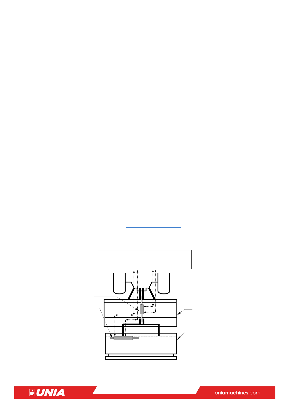
DIAGRAM OF THE HYDRAULIC SYSTEM
cultivator unit + seeder
•
seeder equipped with hydraulic marker triggner
•
the tractor has four outputs for controlling the external hydraulics
Tractor hydraulics
Input/Output
Lift cylinder
Trigger cylinder
Cultivator unit

9
means hydraulic hoses operating alternately – in pairs (i.e. pressure in
1
Read the user manual!
maintenance!
one of them and return in the other)
The cultivator unit with a working width of 4 m exceeds the road width
of 3.0 m allowed in road traffic, hence driving on highways with the
unit mounted on a tractor is forbidden.
HERMES 4.0 cultivator unit should be transported on highways on a trailer, tow truck, etc.,
observing traffic regulations.
2.3. Safety symbols
Read all the safety symbols on the machine and follow the instructions. If you find
that the warning labels are missing or damaged (illegible), replace them with new
ones that can be ordered (purchased) from the machine seller or manufacturer.
C.2.23 – Do not touch the machine components until all of
2
3
4
7
its assemblies stop!
C.2.24 – Keep a safe distance from the machine!
C.2.27 – Do not ride on the machine components!
Place for hanging slings for unloading
8
C.2.26 – Stop the engine and remove the key before starting

10
2.4. Nameplate
MODEL
NUMER / SERIAL
Name of the machine
HERMES 3.0
HERMES 4.0
Type
Mounted
Mounted
Types of rear rollers:
Pipe roller (R), ø 500;
Pipe roller (R), ø 500;
Packer roller (P), ø 530;
Packer roller (P), ø 530;
Tyre roller (G), ø 500;
Tyre roller (G), ø 500;
Weight
R=1120 kg ; P=1310 kg ; G=1350 kg
R=1430 kg ; P=1670 kg ; G=1710 kg
W
3.0 m
4.1 m
L
1.4 m
1.4 m
H
1.7 m
1.7 m
Working width
3,0 m
4.0 m
Working depth
max. 20 cm
max. 20 cm
Capacity
1.5 ha/h
2.0 ha/h
Power demand
min 80 HP/min.130 HP for
min100 HP/min.150 HP for
PTO speed
540 RPM
540/standard/ or 1000 RPM (option)
No. of rotors
12 pcs.
16 pcs.
No. of knives
24 pcs.
32 pcs.
Max working speed
10 km/h
10 km/h
Operator(s)
1 driver
1 driver
PTO drive shaft
BP DS7N061CER07001
BP CS9N061CER07N81 (standard) BP
Each machine is provided with an identification plate containing the following data:
- CE mark
- manufacturer’s mark
- manufacturer’s name and address
- machine type
- number and year of production
- weight
These data are required each time the machine is to be repaired or its parts replaced.
PRODU CER
UNIA FAMAROL Sp. z
TYP / TYPE
ROK PROD. / YEAR
Fig. 5.1 Nameplate
Sales Department
Phone: +48 564510500
e-
mail:info@uniamachin
3. Technical and identification data
HERMES+seeder
HERMES+seeder
7108061PLR07324 6/6 lub 6/8 (option)

11
Operating manual
Warranty card
PTO drive shaft
Cultivating roller /as selected/
Levelling bar
Included in delivery
Included in delivery
Standard
Option
4. Operating Conditions
4.1. Intended Use and Operating Conditions
HERMES power cultivator unit is a modern machine for cultivating medium-heavy and heavy soil.
The purpose of the cultivator unit is loosening and levelling the top soil layer, previously ploughed,
and breaking and crushing the solids of the crusted surface of the field. The soil prepared with the
help of this machine provides optimal conditions for the proper seed emergence. All of these effects
are obtained during only one pass of the machine.
4.2. Restrictions on Use and Unacceptable Methods of Operation
- the user of the machine must not work under the influence of alcohol, drugs, strong medicines, etc.
- only the authorized physician must take decision on the possibility of operating the
machine by invalids and ill persons
- operation of the machine by unqualified people, who do not have adequate knowledge and
skills to operate it, as well as by juveniles is unacceptable
- machines are not to be used in areas of environmental protection and quiet zone without
special permission
- the machine must be lifted into the transport position at the headlands
- do not exceed the recommended max work speed
- the machine is not intended for purposes other than specified in par. 4.1. above
5. Design and Operation Principle
HERMES power cultivator unit (see Fig.7-2) is a machine of a compact design, mounted on the three-
point linkage/hitch of the tractor by means of a frame (7). The drive from the tractor power take-off
shaft to the machine power take-on shaft is transmitted via the PTO drive shaft (supplied with the
harrow) with the safety clutch, to the bevel gear (1). The vertical shaft of this gear transmits the drive
to the cylindrical gear; this wheel drives the serially positioned gears located in the flat transmission
(2).
Discs (3) are fixed to the shafts, on which the gears are mounted. Working knives (4) that rotate
alternately to the right and to the left as working components are attached to these discs.
When rotating in the soil, they break up the lumps, loosen the soil and level the field’s surface.

12
The rotating tyre, pipe or toothed roller (5) installed in the rear part of the machine is designed to further
crumble the clods and compress (compact) the soil surface lightly.
The lift (6) is located above the cultivating roller and is intended to mount the seeder that operates
together with the harrow.
HERMES power cultivator unit can be equipped with the cultivating rollers according to Fig. 7-1
below.
Fig.7-1
Tyre roller /G/ Packer roller/toothed /P/ Pipe roller /R/
3
2
7
1
5
6
4
Fig.7-2
6. Preparation to Work
Preparation of the machine and its start-up is the responsibility of the user.
WARNING ! A SUFFICIENT LEVEL OF GENERAL KNOWLEDGE AND ON AGRICULTURAL MACHINERY
IS REQUIRED TO START THE MACHINE
6.1. Unloading the Machine
Safety instructions
1. The machine may only be lifted at marked points
2. Ensure that the lifting device has enough lifting capacity and there is no risk of the machine
falling

13
3. Use only certified ropes or chains or belts
4. The machine must not be hooked directly to the crane hook; always use ropes, chains or
belts
5. Keep ropes, chains or belts tight when lifting or rotating the machine, in order to prevent its
swinging, which can lead to an accident
6. When lifting the machine with a crane, always check the lifting path and remove all
obstacles
7. Always attach the machine thoroughly to transport it on a trailer, platform, etc.
8. Ensure that the entire area, where the manoeuvres with the unit will be carried out
together with the place, where the vehicle will be positioned, has been previously checked
for possible ‘danger zones’, especially in terms of electric wires, gas or liquid lines, etc. If
there are such ‘danger zones’, choose another place for manoeuvres
9. All personnel should maintain an adequate safety clearance so that, if the machine would fall
unexpectedly, its detached parts will not hit them
Caution! The unit must be positioned stable on an even and hard surface after unloading.
6.2. Connecting the Machine to the Tractor
For connecting the machine to the tractor, see Fig. 8-1
Safety instructions
Warning
Be extremely careful when connecting and disconnecting the machine.
It is strictly forbidden to stay between the tractor and the hitch of the coupling at the moment of
connecting (approaching) and disconnecting (departure). Do not enter between the tractor and the
unit when operating the tractor linkage system.
Switch the tractor hydraulic system to position control.
- Raise the tractor lifting arms so that the machine’s lower hitch bolts are in its axis
- Drive the tractor so that the lower hitches (1) (see Fig. 8-1) of the unit could be inserted into
the tractor hitch and secured with bolts and linchpins. The bottom hitches of the unit are
adjusted by means of pins (3) extend the hitches so that there is no interference between the
unit and the tractor
Using the lifting and tilting arms on the tractor, position the machine so that it is in the
horizontal plane. Mark setting of the arms or install stops
- Connect the upper point of the three-point system of the machine No. 2 to the
tractor with the turnbuckle
The point of connection of the top link on the cultivator unit should be positioned higher than
the point of connection of this link on the tractor
- Fit the PTO drive shaft to the spline ends of the tractor and machine shafts; the outer tube of
the shaft sheath should be on the tractor side
- Immobilize the shaft sheath against rotation with the chains
- Check lifting and lowering of the unit

14
Fig. 8-1
6.3. Connection of Hydraulic Hoses
Safety instructions Warning
The oil in the hydraulic system is under high pressure.
When connecting the hydraulic hoses of the machine to the tractor’s hydraulic system, ensure that
it is depressurized.
Release the overpressure and stop the tractor engine before connecting the hydraulic hoses to the
tractor.
The hydraulic hoses must not be bent or damaged.
Check that the quick couplers of the hydraulic hoses fit properly; otherwise install the correct ones.
With functional hydraulic connections of the tractor and attachment, sockets and plugs should be
marked to avoid wrong connections! Shifting the connections leads to the function being reversed
(e.g. lifting/lowering.)
Remember!
We recommend replacement of the machine hydraulic hoses after 5 years of use.
6.4. Lubrication
Safety instructions Caution
1. Always wear appropriate protective clothing when working with oils and greases
2. Protect your skin against contact with oils and greases
3. Never wash your hands with used oil or grease! They usually contain metal particles that can
hurt your hands, and the oil can also deepen and infect cuts
4. Read leaflets and safety instructions on lubricants
5. Most synthetic oils have corrosive properties and cause severe skin irritation
6. Contact your doctor immediately, if oil or grease causes skin irritation
7. If oil spills onto the ground, prevent it from spreading. Collect the oil with a cloth. Handle
the collected oil in accordance with the applicable regulations on environmental protection
and waste management

15
Lubrication point
No. Fig.8-2
Component
No. of lubrication
points
Type of lubricant
Interval
Notes
1 2 3 4 5 6
1
Lift axle 1
ŁT-41
every 50h
through grease nipple
2 Fig.7-1
Rear roller axle
2 ŁT 41
every 50h
through grease nipple
3
Cylinder heads
2 ŁT 41
every 50h
through grease nipple
4
Cylinder piston rod
1 ŁT-41
every 50h
on the surface
5
PTO drive shaft
1
Acc. to PTO instructions
Bevel gear (7)
The gear is filled with HIPOL 15 or GL 4 gear oil in an amount of 5 liters (4.5 kg).
Change the oil with a new one after purchasing a new machine and after 50 hours of its
operation.
Then, the oil should be changed every 500 hours of operation.
Cylindrical gear – bath (6).
Checking the oil level in the cylindrical gear (bath) takes place with the oil filler cap, on which the dip rod
is mounted. After inserting the oil cap with the dip rod into the filler hole, the oil should be at a height
between 10-15 mm from the bottom edge of the dip rod, indicating a sufficient oil level. Screw the cap
to the stop after checking the level.
Lubrication table
Check the lubricant level once a week.
Check the grease level by placing the unit in the horizontal plane.
If the oil level is too low, top up with CLP 460 oil that the bath is filled with.
Fig.8-2
drain
7. Settings and Adjustments
7.1. Adjustment of the Vertical Position
HERMES cultivator unit must be perpendicular to the ground during operation. Mount the unit on the
tractor before the adjustment and lower it into the working position on a flat and hard surface.
Adjustment is carried out using the adjusting screw (1), Fig.9-1, connecting the top point of the tractor
three-point system with the upper point of the machine hitch.
Fig.
Fig.9-1 Fig.9-2
Fig.9-3
Fig.9-4

16
7.2. Adjustment of Working Depth
upper gear
lower gear
tractor PTO speed
working components’ speed
3.0
4.0
3.0
4.0
3.0
4.0
3.0
4.0
16
17
17
18
540/min
540/1000
292/min
175/323
17
18
16
17
540/min
540/1000
311/min
196/362
The working depth of the cultivating knives is determined in relation to the position of the rear roller.
Adjustments of the roller position are made by turning the cranks (1), Fig.9-2, located on both sides of
the harrow. Remember that the number of revolutions of the right and left crank was the same, which
ensures an even working depth on both sides of the harrow. The more screwed in the screw, the greater
the working depth.
Check the working depth by pushing the rigid strip into the cultivated soil until you feel resistance.
The depth of the strip insertion in the cultivated soil is the working depth.
7.3. Adjustment of Fender Beam
The adjustment is made by raising or lowering the beam and securing it in a given position by means
of bolts (1), Fig.9-3, secured with linchpins (on both holders equally). The beam located directly behind
the rotors serves for additional crumbling of clods on the soil surface. The lower the beam is set, the
greater the crumbling. The beam cannot work like a drag, i.e. scrape the layers of loosened soil.
7.4. Adjustment of Side Shields
The shields (RH and LH) are pivoted so that the stones can leave the work area quickly. Set the shields
by loosening the screws (1), Fig. 9-4, and shifting the shields into a suitable notch so that they do not
sink deeper than 2 cm into the soil. A deeper setting can damage the shields.
7.5. Adjustment of Scrapers
In order to properly clean the pipe of the tyre and toothed rollers from the soil sticking to them, the
size of the gap between the pipe and the scraper should be as small as possible. The scraper settings
are made by loosening the nut on the scraper fastening screw, then setting the scraper in the
recommended position and tightening the nut. After setting all the scrapers, ensure that the scrapers
do not rub against the pipe during rotation of the roller. After one side of the scraper become worn,
turn it to the other side.
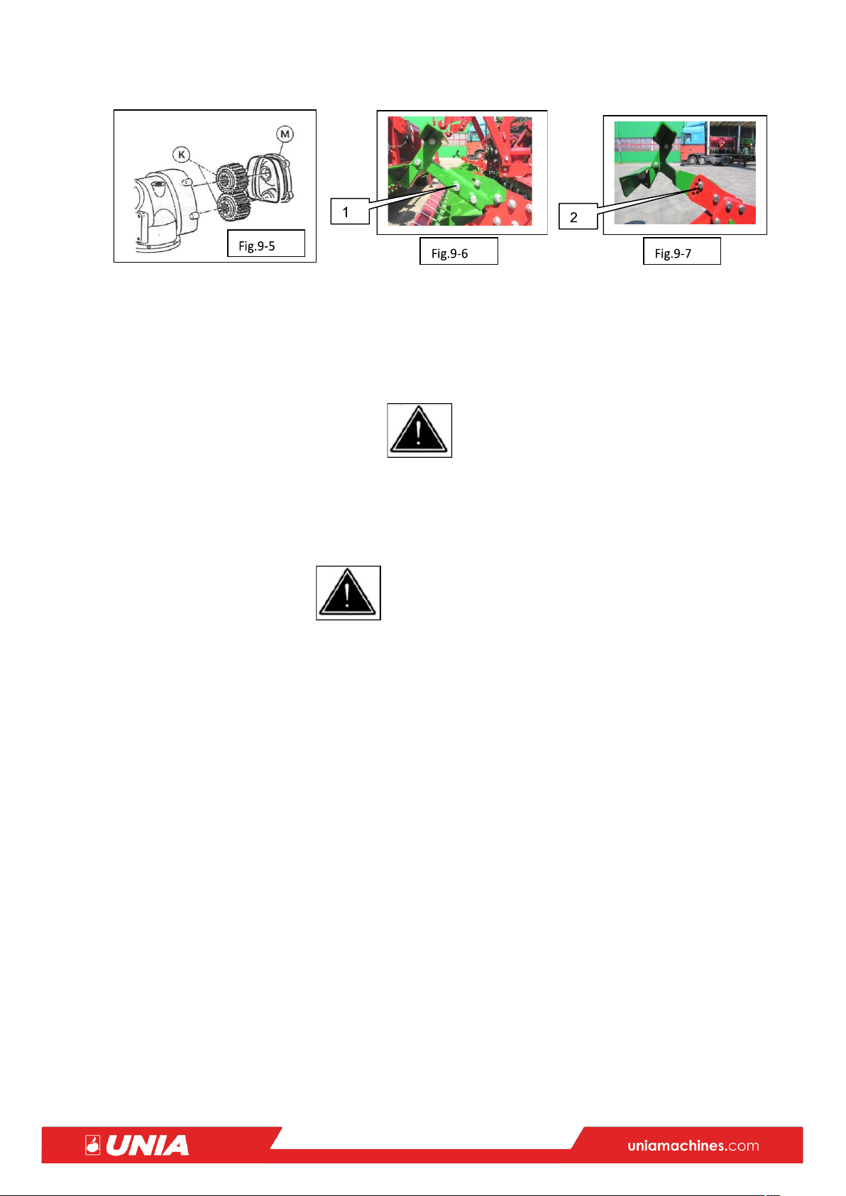
7.6. Setting Supports Under the Seed Drill Wheels
Before starting work with HERMES + seeder unit and after each working depth change, set the
angle/bolts (1) (if any), Fig. 6-9, and the height of the supports/bolts (2), Fig.9-7, so that there was no
interference between the seeder and the rotary harrow after placing the seeder on the supports.
7.7. Changing the Speed of Working Knives
In order to increase the intensity of soil crumbling, it is necessary to increase speed of the rotors with
working knives by replacing the gears in the gear (see Fig. 9-5).
The speed of the PTO must be 540 RPM or 1000 RPM (Hermes 4.0 option). Such parameters ensure
the proper operation of the machine.
Caution! After replacing the wheels (up-down or down-up), the mating wheels must touch the same tooth working surfaces as before the replacement!
17
To do this, unscrew the cover (M)
(cleaning it thoroughly in advance, so that no dirt gets inside), and remove it together with the
bearings. Move the toothed wheels (K) off the spline shafts and shift their positions. Then, put on the
gear cover and screw it on. Pay attention to the correct position of the gasket.
More intensive soil crumbling can also be achieved by increasing the speed of travel, but the power
demand increases. However, never exceed max operating speed specified by the manufacturer in the
machine operating manuals.
CAUTION ! POSSIBILITY OF BURNS
If replacement of wheels takes place immediately after interrupted work, wait until the transmission has cooled down. Remove the PTO drive shaft from the tractor after stopping the tractor engine and removing the keys.
8. Work with HERMES Unit and Operating Conditions
Safety instructions, section 4
Observe the following rules in order to achieve the correct effects of the cultivator unit operation:
1. Ensure that the machine is correctly attached to the tractor.
2. Read this OPERATING MANUAL thoroughly
3. Check the condition of screw connections and condition of working components before
driving to the field
4. Check and adjust the working depth, if required
5. Keep an even speed
6. Always clean the machine after finishing work
7. Replace defective parts with original, new ones, as soon as possible
8. At the headlands, raise the unit to a height that allows the manoeuvre to be performed
without hitting of the working components against the soil
9. Drive the unit in a straight line during subsequent passages, without underlap. When
working with the seeder, drive the machines following the traces of the seeder markers
9. Avoid sudden jerks
10. Repair any defects immediately after their detection
11. Avoid working on stony soils
12. Use the right lubricants and observe the lubrication intervals, according to the lubrication
chart (par. 8.2.2)
13. Check the tightening of the bolts and nuts every 30 hours of operation. Tightening torque for
knife fixing bolts– 350 Nm

18
14. When changing the knives, pay attention as not to change the right knives with the left ones and
vice versa. The knife blade should be directed in the direction of rotation. After installing the knives,
check manually that the rotors with knives rotate without jamming
15. If the bolts in the PTO drive shast (if the shaft of this type is mounted) get sheared, protecting the
machine from damage, only use the bolts recommended by the factory, i.e. M8 x 60-8,8 B bolts,
acc. to PN-85 / M-82101, for the replacement. The strength designation of the screw 8.8 is
embossed on the screw head.
16. Do not adjust the bolts of the overload clutch in the PTO drive shaft (if the shaft of this type
is mounted)
When starting work, activate the PTO rotation in the transport position and lower the unit
smoothly after reaching 540 RPM or 1000 RPM (HERMES 4.0 option), while driving forward.
Caution !
It is forbidden to start working with the machine knife buried in the ground.
The macine must not be driven backwards.
9. Delivery and Shipment
1. The shipment conditions are set by the manufacturer, if there are no other arrangements with
the recipient
2. The buyer agrees the date of receipt of the machine with the manufacturer
3. The seller/importer is responsible for the packaging of the machine.
4. Loading the machine belongs to the manufacturer. During transport, the carrier is
responsible for the machine
SHIPMENT
Caution !
ALWAYS SHIP THE MACHINE IN THE TRANSPORT POSITION – MOUNTED AND RAISED ON THE
TRACTOR HITCH; IT IS FORBIDDEN TO STAY WITHIN THE TRACTOR + THE MACHINE MANOEUVRE
RANGE
When moving the unit, please observe the following rules:
1. When driving on a highway, always obey the traffic rules and prepare the unit in the manner
required by the regulations (i.e. appropriate lights, direction indicators, warning triangle, etc.),
according to par. 2.2 above.
2. All devices that set the machine into motion, such as chains, rollers, axles, etc., should be
connected in such a way that accidental movements while driving do not affect the
machine’s ability to operate or transport in the future.
3. Driving and gear shifting can negatively affect the mechanism of lowering and lifting the tractor
and the machine mounted on it. That’s why you should always leave enough room for
manoeuvres and control your gears.
4. The machine may not carry passengers or any materials.
5. If you are transporting the machine, for example, on a trailer or platform, it must be tied tightly
with chains, ropes or belts. Use only certified ropes, belts or chains. Always check their condition
before use.
6. Switch the machine to the transport position even for short distances. In the case of work with
a coupling (lift) mounted, without a seeder or with a seeder raised on it, the coupling (lift) must
be secured with bolts against self-lowering (see Fig.11-1.)

19
10. Maintenance and Storage
10.1. Maintenance
Warning !
DANGER OF INJURY OR CRUSHING
1. Always ensure that the tractor engine is switched off and the keys are removed from the ignition
switch before cleaning, lubricating, setting, repairing or adjusting,. Disconnect the power supply.
2. Adjustments, lubrication, checking the condition of the machine, cleaning, repairing and
replacing the working knives should only be performed after removing the PTO drive shaft, with
the machine supported on hard ground or after setting the harrow on the trestles to prevent its
falling down.
3. Clean the unit of soil and plant debris every time after finishing work; then, inspect the
connections of parts and assemblies.
4. Tighten all loose screw connections, replace worn parts with new ones and repair or scrap any
damaged parts.
5. Use appropriate clothing and protective gloves!
CAUTION !
UNDER NO CIRCUMSTANCES SHOULD ANY MAINTENANCE OR REPAIR WORK BE CARRIED OUT, IF
THE SEED DRILL IS MOUNTED ON THE COUPLING
CAUTION !
Use typical protection hardware, such as pins and linchpins to secure the suspension journals and
all bolts included in the aggregate.
It is forbidden to use substitute means of protection, such as: screws, rods or wires, which during
work or transport may be sheared or fall out, and thus may cause damage to the tractor and the
cultivator unit, and to jeopardize the safety of other road users.
Fig.11-1
10.2. Storage
After the season of work, clean the unit thoroughly, and wash surfaces that are not subject to painting
(e.g. suspension journals) or components wiped by the wiping soil (working knives, steel shaft surfaces,
etc.) with Antykor kerosene and protected them against corrosion by coating with Antykor 1 grease.
The machine must be stored absolutely in its rest position. Lower all working assemblies to the ground
for good stability. We recommend storage of the machine in a covered place, and in closed rooms with
well-functioning ventilation. When stored in a non-roofed location, it is necessary to periodically top
up the lubricant on the components subject to preservation, due to the effects of atmospheric
precipitation.
Store the machine in locations inaccessible to unauthorized persons, especially children as well as pets.
Repair the local damage to the paint coating by re-coating them with paint.
11. Disassembly, Scrapping and Utilization
The user of the machine, in accordance with the environmental protection provisions, is obliged to
conduct proper waste management, agreed with the relevant local authorities.

20
As part of these activities, the user should, at the time of the replacement and scrapping of parts and assemblies or the liquidation of the entire unit:
preserve and store in the warehouse parts that are still suitable for further use
transfer the scrapped metal parts to the scrap collection agents
products made of cardboard, paper, plastics, rubber, etc. should be transferred to
the recyclable material purchasing agents
hand over the used oil to the companies carrying out the collection of used oils and
lubricants, or follow local regulations regarding waste management for environmental
protection
12. Responsibilities of the Manufacturer
The manufacturer shall not be liable if the machine is operated contrary to the law, safety regulations
or recommendations of this manual. Due to the fact that during the operation of the machine, there
may be situations not provided for herein, the user should always follow the general safety rules.
The manufacturer's responsibility is excluded in the event of arbitrary use on the machine other than
original spare parts or parts approved by the manufacturer.
The manufacturer’s responsibility shall be excluded in the event of not authorized use in the machine
spare parts other than original or parts other than approved by the manufacturer.
The manufacturer shall not be liable for indirect damages, including damage to other machines or
equipment.
The manufacturer’s liability shall not cover improper (or departing from the expected) results of work,
if any section of this manual or the operating manual of the attached machine is not observed. The
owner of the machine is responsible for its operation and maintenance.
The owner of the machine is responsible for the appropriate qualifications of operators and their
knowledge of how to operate the machine and rules of its operation.
Remember that improper operation of the machine poses a risk to people, animals, water reservoirs
and arable fields. Always follow the instructions of manufacturers of machines and equipment, seeds
as well as plant protection products and fertilizers contained in specialist instructions.
NOTE!
OTHER DESIGN SOLUTIONS ARE ALLOWED, WHICH DO NOT NECESSITATE THE CHANGE OF THIS
MANUAL
13. Warranty Terms and Conditions
Warranty terms and conditions are included in a separate document, Warranty Card, attached to the
machine.
14. Additional Information

21
In order to use the effects of the power harrow work to maximum, i.e. shorten the time of soil
preparation for seeding and seeding itself, the factory equips the harrow with a special hydraulic
coupling (lift) allowing the seeder to be attached behind the cultivator unit. One-time passage of the
combine unit: tractor + power harrow + seeder through the field, e.g. after winter ploughing, leaves
the field sown in very well prepared soil. Working with such a combine unit shortens the time
associated with seeding and reduces costs (by reducing fuel consumption). The coupling (lift) is a device
fulfilling the role of a three-point linkage system. The connection options are the same as for the tractor
three-point linkage system. HERMES power cultivator unit can be used for mounting seeders on it, with
seeding units driven from the seeder wheels, such as mounted POLONEZ and POZNANIAK seeders, etc.

22
UWAGI I NOTATKI
. . . . . . . . . . . . . . . . . . . . . . . . . . . . . . . . . . . . . . . . . . . . . . . . . . . . . . . . . . . . . . . . . . . .
. . . . . . . . . . . . . . . . . . . . . . . . . . . . . . . . . . . . . . . . . . . . . . . . . . . . . . . . . . . . . . . . . . . .
. . . . . . . . . . . . . . . . . . . . . . . . . . . . . . . . . . . . . . . . . . . . . . . . . . . . . . . . . . . . . . . . . . . .
. . . . . . . . . . . . . . . . . . . . . . . . . . . . . . . . . . . . . . . . . . . . . . . . . . . . . . . . . . . . . . . . . . . .
. . . . . . . . . . . . . . . . . . . . . . . . . . . . . . . . . . . . . . . . . . . . . . . . . . . . . . . . . . . . . . . . . . . .
. . . . . . . . . . . . . . . . . . . . . . . . . . . . . . . . . . . . . . . . . . . . . . . . . . . . . . . . . . . . . . . . . . . .
. . . . . . . . . . . . . . . . . . . . . . . . . . . . . . . . . . . . . . . . . . . . . . . . . . . . . . . . . . . . . . . . . . . .
. . . . . . . . . . . . . . . . . . . . . . . . . . . . . . . . . . . . . . . . . . . . . . . . . . . . . . . . . . . . . . . . . . . .
. . . . . . . . . . . . . . . . . . . . . . . . . . . . . . . . . . . . . . . . . . . . . . . . . . . . . . . . . . . . . . . . . . . .
. . . . . . . . . . . . . . . . . . . . . . . . . . . . . . . . . . . . . . . . . . . . . . . . . . . . . . . . . . . . . . . . . . . .
. . . . . . . . . . . . . . . . . . . . . . . . . . . . . . . . . . . . . . . . . . . . . . . . . . . . . . . . . . . . . . . . . . . .
. . . . . . . . . . . . . . . . . . . . . . . . . . . . . . . . . . . . . . . . . . . . . . . . . . . . . . . . . . . . . . . . . . . .
. . . . . . . . . . . . . . . . . . . . . . . . . . . . . . . . . . . . . . . . . . . . . . . . . . . . . . . . . . . . . . . . . . . .
. . . . . . . . . . . . . . . . . . . . . . . . . . . . . . . . . . . . . . . . . . . . . . . . . . . . . . . . . . . . . . . . . . . .
. . . . . . . . . . . . . . . . . . . . . . . . . . . . . . . . . . . . . . . . . . . . . . . . . . . . . . . . . . . . . . . . . . . .
. . . . . . . . . . . . . . . . . . . . . . . . . . . . . . . . . . . . . . . . . . . . . . . . . . . . . . . . . . . . . . . . . . . .
. . . . . . . . . . . . . . . . . . . . . . . . . . . . . . . . . . . . . . . . . . . . . . . . . . . . . . . . . . . . . . . . . . . .
. . . . . . . . . . . . . . . . . . . . . . . . . . . . . . . . . . . . . . . . . . . . . . . . . . . . . . . . . . . . . . . . . . . .
. . . . . . . . . . . . . . . . . . . . . . . . . . . . . . . . . . . . . . . . . . . . . . . . . . . . . . . . . . . . . . . . . . . .
. . . . . . . . . . . . . . . . . . . . . . . . . . . . . . . . . . . . . . . . . . . . . . . . . . . . . . . . . . . . . . . . . . . .
. . . . . . . . . . . . . . . . . . . . . . . . . . . . . . . . . . . . . . . . . . . . . . . . . . . . . . . . . . . . . . . . . . . .
. . . . . . . . . . . . . . . . . . . . . . . . . . . . . . . . . . . . . . . . . . . . . . . . . . . . . . . . . . . . . . . . . . . .
. . . . . . . . . . . . . . . . . . . . . . . . . . . . . . . . . . . . . . . . . . . . . . . . . . . . . . . . . . . . . . . . . . . .
. . . . . . . . . . . . . . . . . . . . . . . . . . . . . . . . . . . . . . . . . . . . . . . . . . . . . . . . . . . . . . . . . . . .
. . . . . . . . . . . . . . . . . . . . . . . . . . . . . . . . . . . . . . . . . . . . . . . . . . . . . . . . . . . . . . . . . . . .
. . . . . . . . . . . . . . . . . . . . . . . . . . . . . . . . . . . . . . . . . . . . . . . . . . . . . . . . . . . . . . . . . . . .
. . . . . . . . . . . . . . . . . . . . . . . . . . . . . . . . . . . . . . . . . . . . . . . . . . . . . . . . . . . . . . . . . . . .
. . . . . . . . . . . . . . . . . . . . . . . . . . . . . . . . . . . . . . . . . . . . . . . . . . . . . . . . . . . . . . . . . . . .
. . . . . . . . . . . . . . . . . . . . . . . . . . . . . . . . . . . . . . . . . . . . . . . . . . . . . . . . . . . . . . . . . . . .
. . . . . . . . . . . . . . . . . . . . . . . . . . . . . . . . . . . . . . . . . . . . . . . . . . . . . . . . . . . . . . . . . . . .
. . . . . . . . . . . . . . . . . . . . . . . . . . . . . . . . . . . . . . . . . . . . . . . . . . . . . . . . . . . . . . . . . . . .
. . . . . . . . . . . . . . . . . . . . . . . . . . . . . . . . . . . . . . . . . . . . . . . . . . . . . . . . . . . . . . . . . . . .
. . . . . . . . . . . . . . . . . . . . . . . . . . . . . . . . . . . . . . . . . . . . . . . . . . . . . . . . . . . . . . . . . . . .
. . . . . . . . . . . . . . . . . . . . . . . . . . . . . . . . . . . . . . . . . . . . . . . . . . . . . . . . . . . . . . . . . . . .
. . . . . . . . . . . . . . . . . . . . . . . . . . . . . . . . . . . . . . . . . . . . . . . . . . . . . . . . . . . . . . . . . . . .
. . . . . . . . . . . . . . . . . . . . . . . . . . . . . . . . . . . . . . . . . . . . . . . . . . . . . . . . . . . . . . . . . . . .
. . . . . . . . . . . . . . . . . . . . . . . . . . . . . . . . . . . . . . . . . . . . . . . . . . . . . . . . . . . . . . . . . . . .
. . . . . . . . . . . . . . . . . . . . . . . . . . . . . . . . . . . . . . . . . . . . . . . . . . . . . . . . . . . . . . . . . . . .
. . . . . . . . . . . . . . . . . . . . . . . . . . . . . . . . . . . . . . . . . . . . . . . . . . . . . . . . . . . . . . . . . . . .
. . . . . . . . . . . . . . . . . . . . . . . . . . . . . . . . . . . . . . . . . . . . . . . . . . . . . . . . . . . . . . . . . . . .
. . . . . . . . . . . . . . . . . . . . . . . . . . . . . . . . . . . . . . . . . . . . . . . . . . . . . . . . . . . . . . . . . . . .
. . . . . . . . . . . . . . . . . . . . . . . . . . . . . . . . . . . . . . . . . . . . . . . . . . . . . . . . . . . . . . . . . . . .
. . . . . . . . . . . . . . . . . . . . . . . . . . . . . . . . . . . . . . . . . . . . . . . . . . . . . . . . . . . . . . . . . . . .

23
UNIA-FAMAROL Sp. z o.o.
ul. Przemysłowa 100
PL 76-200 SŁUPSK
tel. + 48 59 841 80 01
fax. + 48 59 841 37 25
Serwis tel. + 48 59 841 80 27
uniamachines.com
 Loading...