

Page 1

Operating and mounting manual (translation)
EV / EVF
Operating and mounting manual
Safety shut off valve solenoid valve
EV / EVF
Contents
1.0 General Remarks
1.1 Valve data
1.2 Application
2.0 Danger Notices
2.1 Safety terms
2.2 Safety notice
2.3 Qualified staff
2.4 Unauthorized modification and spare part production
2.5 Unauthorized operation
2.6 Safety information for the use in explosion-prone areas guideline 94/9/EC
3.0 Handling
3.1 Transport
3.2 Storage
3.3 Handling before mounting
4.0 Product Description
4.1 Function
4.2 Technical data
4.3 Marking
5.0 Installation
5.1 Warning of dangers during installation, operation and maintenance
5.2 Installation
6.0 Operation
6.1 Commissioning
6.2 Shutting down
6.3 Maintenance
6.4 Putting back into operating
7.0 Troubleshooting
7.1 Detection of defects
7.2 Troubleshooting plan
8.0 Dismantling of the Valve
8.1 Replacement of wear parts
9.0 Warranty
10.0 Explanations on Codes and Directives
11.0 Drawing
11.1 Sectional drawing
11.2 View drawing
11.3 List of parts
12.0 Declaration of Conformity
_______________________________________________________________________________________________________
220.100.091-05 Page 1 /21 Version: 06/2017
TM 4474
Page 2

Operating and mounting manual (translation)
EV / EVF
1.0 General Remarks
This operating manual includes instructions to assemble and operate the valve in the prescribed and
safe way. Additionally, the adeqaute operating instructions of each special solenoid drive must
be considered.
Series MG... 220.000.038
Series MG...X 220.000.040
Series MG…Xme 220.000.039
If any difficulties appear that can not be solved by means of the operation instructions, further
information may be demanded from the manufacturer.
This operating manual is in accordance with the relevant valid EN safety standards and the valid
prescriptions and rules of the Federal Republic of Germany.
If the solenoids are used abroad of the FRG, the operator and/or the person who is responsible for the
plant concept must take care that the valid national rules are met. The manufacturer reserves the right
of any technical change and improvement. The use of these operating instructions suppose the
qualification of the user according to paragraph 2.3 “qualified staff”.
The operating staff must be trained in accordance with the operating instructions. The operating
manual must always be available at the location where used.
1.1 Valve data
Manufacturer:
UNI Geräte E. Mangelmann
Elektrotechnische Fabrik GmbH
Holtumsweg 13
D-47652 Weeze
Telefon: +49 (0) 2837/9134-0
Fax: +49 (0) 2837/1444
E-Mail: info@uni-geraete.de
Homepage: www.uni-geraete.de
Designation
Directly functioning, currentless closed, spring safety shut off valve with magnet drive.
Type test acc. to DIN EN 264
Working pressure: 5 EV(F) 5bar
10 EV(F) 10bar
25 EV(F) 25bar
40 EV(F) 40bar
Ambient temperature: -10°C to + 60°C (263K to 333K)
Medium temperature: EV -10°C bis + 140°C (263K bis 413K)
EVF -10°C bis + 200° C (263K bis 473K)
Working pressure: 100-EVF 5 / 7 16bar
Medium temperature: -20°C to + 60°C (253K to 333K)
Ambient temperature: -20°C to + 60°C (253K to 333K)
Fitting position: vertical drive ± 5°, with order supplement „W“ vertical or
horizontal.
Working pressure: 100-EVF 10N 100bar
Medium temperature: -10°C to + 60°C (263K to 333K)
Ambient temperature: -10°C to + 60°C (263K to 333K)
Fitting position: vertical drive
Switching cycles: see operating instructions solenoid drive
_______________________________________________________________________________________________________
220.100.091-05 Page 2 /21 Version: 06/2017
TM 4474
Page 3
Operating and mounting manual (translation)
EV / EVF
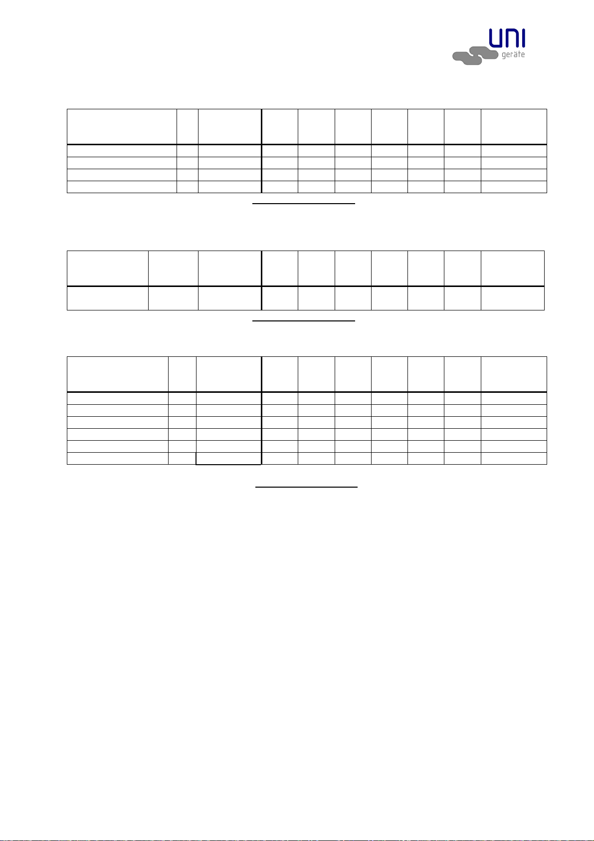
Flange connection measures acc. to DIN EN 1092-2 / ANSI
Flange DN
Flange ANSI
PN TÜV-
Report-no.
15
(5N)
1/2
20
(7N)
3/4
25
(10N)
1
32
(12N)
1 1/4
40
(15N)
1 1/2
50
(20N)
2
Test
Pressure
(*) PT
5 EV..NÜ..92/93 25 S7/99 X X X O O O PT 16
10 EV..NÜ..92/93 40 S7/99 X X X O O - PT 25
25 EV..NÜ..92/93(#) 40 S7/99 X X X O O - PT 40
40 EV..NÜ..92/93 40 S7/99 X X X O - - PT 40
(*) Test pressure to perform leakage test "No FUNCTION TEST"
X Type test acc., O Acceptance test certificate 3.2 possible, - not available,
(#) For liquefied gas in its liquid form according to DIN 32725
Threaded connection dimension at DIN ISO 228-1
Connection G PN
Class
TÜV-
Report-no.
1/2
(5)
3/4
(7) 1 (10)
1 1/4
(12)
1 1/2
(15) 2 (20)
Test
pressure
(*) PT
100-EVF...
100
900/1500
- O O - - - -
PT 100
(*) Test pressure to perform leakage test "No FUNCTION TEST"
X Type test acc., O Acceptance test certificate 3.2 possible, - not available,
Flange connection measures acc. to DIN EN 1092-2 / ANSI
Flange DN
Flange ANSI
PN TÜV-
Report-no.
15
(5N)
1/2
20
(7N)
3/4
25
(10N)
1
32
(12N)
1 1/4
40
(15N)
1 1/2
50
(20N)
2
Test
Pressure
(*) PT
5 EVF..NÜ..92/93 40 S8/99 X X X O O O PT 16
10 EVF..NÜ..92/93 40 S8/99 X X X O O - PT 25
25 EVF..NÜ..92/93 40 S8/99 X X X O O - PT 40
40 EVF..NÜ..92/93 40 S8/99 X X X O - - PT 40
40 EVF..NH.Ü.. 40 S8/99 X X X - - - PT 40
100 EVF..N.. 100 - - - O(**) - - - PT 100
(**) Passage 12mm
(*) Test pressure to perform leakage test "No FUNCTION TEST"
X Type test acc., O Acceptance test certificate 3.2 possible, - not available,
Voltage: VDC 12 – 440 (–15% bis +10%)
VAC 24 – 500 (–15% bis +10%)
Protection type: IP54 or IP65
Frequency: 40 – 60 Hz
Power: 10 – 4000W
Details to the electrical data can be found on the type signand the adeqaute operating instructions of
the solenoid valves.
1.2 Application
The UNI Geräte solenoid valve EV and EVF are used as automatic safety shut-off valves to secure, to
limit, shut-off and release Liquid gas heating installation and in steam boiler plant.
Qualified for fuel oil EL, M (EV) according to DIN 51603 and for liquid gas to DIN 61522 in liquid state
and other liquids having a viscosity rate up to 75mm²/s and for fuel oil S (EVF).
If used in other cases, the operator must carefully check if construction/design of valve, accessories
and materials are suitable for the new application. The range of application is subject to the
responsibility of the plant planner. The service life of the valve is 20 years.
_______________________________________________________________________________________________________
220.100.091-05 Page 3 /21 Version: 06/2017
TM 4474
Page 4

Operating and mounting manual (translation)
EV / EVF
2.0 Danger Notices
2.1 Safety terms
The signal terms DANGER, CAUTION und NOTICE are used in this operating manual in case of
notices concerning special dangers, or for unusal information requiring a special marking.
DANGER! means that in case of non-observance there is danger to life and/or
considerable damage.
CAUTION! means that in case of non-observance there is danger of injury and/or
damage.
NOTICE! means that attention is drawn to technical correlations/connections.
Observance of other, not especially marked notices concerning transport, assembly, operation and
maintenance and other data (in the operating manual, product documentation and at the unit itself) is
also essential, in order to avoid disturbances that might affect direct or indirect damage to property or
injury to persons.
2.2 Safety notice
Non observance of safety instructions can lead to loss of any claim for damages.
Non observance can lead to the following mentioned dangers:
Failure of important functions of the valve/plant
Endangering of persons by electrical or mechanical influences.
Protection against accidental contact for moving parts may not be removed as long as the
valve is in operation.
Leakage of dangerous media (e.g. explosive, toxic, hot) must be removed in the way that
there is no danger for persons or environment. Laws and regulations must be observed.
2.3 Qualified staff
These are persons who are familiar with erection, assembly, starting, operation and maintenance of
the product and who have special qualifications acc. to their activities and functions, e.g.:
Instruction and obligation to carry out and meet all regional and in-house orders and
requirements.
Education or instruction according to the safety engineering standards in use and
maintenance of adequate safety and working protection equipment.
Training in first aid.
2.4 Unauthorized modification and spare part production
Modification or changes of the valve are only allowed after agreement of the manufacturer. Original
drawings and accessories authorized by the manufacturer are for safety purposes. The use of other
parts or unauthorized changes at the valve by third persons may cancel and abolish the
manufacturere’s liability for resulting consequences.
2.5 Unauthorized operation
Operational reliability of the delivered valve is only guaranteed in case of determined use in
accordance to paragraph 1 of the operating manual. The application limits mentioned on the type
sign may on no account be exceeded.
2.6 Safety information for the use in explosion-prone areas guideline 2014/34/EU
The temperature of the medium must not exceed the respective temperature class, and
respectively, the respective maximum permitted medium temperature as per operation
guideline.
If the valve is heated (e.g. heating jacket), care must be taken, that the specified temperature
class is kept in the time.
_______________________________________________________________________________________________________
220.100.091-05 Page 4 /21 Version: 06/2017
TM 4474
Page 5
Operating and mounting manual (translation)
EV / EVF
The valve must be connected to the ground.
In the case most simple this can be realized via pipe screws by means of tooth disc.
Otherwise the connection to the ground must be implemented by other measures e.g. cable
links.
Control valves, electrical and electrical/mechanical drives as well as sensors must undergo a
separate conformity check as per ATEX. In doing so the respective safety and explosion
protection information in the operation instructions are to taken into special consideration.
Any modifications whatsoever to the valve are not allowed. The ATEX approval is void with
immediate effect if the valve is modified without prior authorisation (even including painting).
UNI-Geräte GmbH must be consulted before any modifications are made.
Furthermore we point out the guideline 95/C332/06(ATEX 118a), which include the minimum
regulations for the improvement of the health-related situation and the safety of the employees, who
might be jeopardized by an explosive atmosphere.
3.0 Handling
3.1 Transport
For any transport works, the generally recognised technical rules and standards as well as rules for
prevention of accidents must be observed.
In case of transport, storage and stopping, the flange protection caps must be mounted at both valve
flanges.
The goods to be transported must be carefully treated. During transport, the valve must be protected
against strokes, impacts or vibration. The coat of lacquer may not be damaged. Transport temperature
is –20°C up to +60°C.
Never transport the valve at screwed cable glands, appliance plugs or add-on units. The valve
can be transported at ring nuts, flange borings or by means of a belt under the solenoid drive.
Transport the valve in a case or on a pallet with smooth base and put it softly on plain floor. Never put
the valve on limit switch box.
The goods must be checked on completeness and transport damage. See also section 9.0
3.2 Storage
If the valve is not installed immediately after delivery, it must be stored properly.
Storage temperature -20°C up to +60°C, dry and clean.
The lacquering protects against corrosion in neutral dry atmosphere. Do not damage colour.
In humid rooms, a drying agent or a heating resp. is necessary because of condensation of
water.
Requirements according to DIN 7716 (products made of caoutchouc and rubber) must be met.
3.3 Handling before mounting
In case of valve with protection caps, they must be removed before being mounted!
Protect against atmospheric influences such as humidity.
Appropriate treatment protects against damage.
4.0 Product Description
The UNI-Geräte solenoid valves of the series EV and EVF are directly controlled currentless closed
shut-off valves with fast shut-off function as per DIN EN 264 (liquid gas in liquid gas phase as per DIN
51622) with solenoid valve.
Sectional drawing 11.1 Fig. in Fig. 1 and 6 shows the valve construction.
_______________________________________________________________________________________________________
220.100.091-05 Page 5 /21 Version: 06/2017
TM 4474
Page 6
Operating and mounting manual (translation)
1)
1)
EV / EVF
4.1 Function
On switching on of the solenoid drive (800) the solenoid core (207) is pulled against the upper part of
housing (106). The pressure spring (503) is further prestressed and the valve disk (200) opens the
valve cross section. The valve is open.
On shutting off, supply interruption or supply failure the valve closes to the solenoid drive. The valve
disk (200) closes due to the pre-stress of the pressure spring (5 03). The valve is closed.
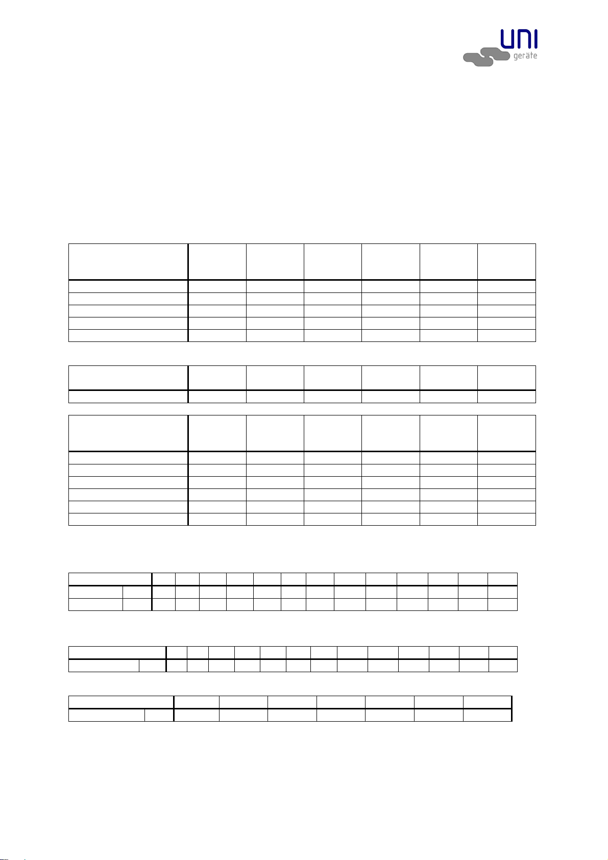
4.2 Technical data
Opening times: 0,3 – 0,7s , depends upon nominal width
Closing times: 1s
Solenoid –drive types MG...
Flange DN
Flange ANSI
5 EV...NÜ..92/93
10 EV...NÜ..92/93
25 EV...NÜA..92/93
25 EV…NÜA..92/93(#)
40 EV...NÜA..92/93
(#) For liquefied gas in its liquid
Connection G
ANSI
100-EVF....
Flange DN
Flange ANSI
5 EVF...NÜ..92/93
10 EVF...NÜ..92/93
25 EVF...NÜA..92/93
40 EVF...NÜA..92/93
40 EVF...NH.Ü..
100 EVF…N..
Drive types with “A” consist of pickup and holding winding
Max. valve loading by pipe power
The indicated moments may not work longer than 10s.
DN 8 10 15 20 25 32 40 50 65 80 100 125 150
Torsion Nm
Bending Nm
1)
Not valid in case of valves with flanges
80 35 50 86 125 160 200 250
35 70 105 225 340 475 610 1100 1600 2400 5000 6000 7600
Starting torque, pipe screws greased
DN 8 10 15 20 25 32 40 50 65 80 100 125 150
Torque Nm
20 30 30 30 30 50 50 50 50 50 80 160 160
Starting torque, product screws and nuts greased
Screw M6 M8 M10 M12 M16 M20 M24
Torque Nm
4.3 Marking
The type sign on the solenoid drive has the following information:
Fabricator
Valve type, nominal width, pressure and temperature indication, fitting position
Year of construction/ production no.
_______________________________________________________________________________________________________
220.100.091-05 Page 6 /21 Version: 06/2017
TM 4474
15
(5N)
1/2
014 014 016 018 019A5 019A2
016 016 019A5 018A2 019A1 016A1 016A1 018A2 019A2 019A3 018A1 018A1 019A1 - - 019A1 019A1 019A2 020A2 - -
1/2
(5)
019A5 019A5 - - - -
15
(5N)
1/2
014 014 016 019A5 019A5 019A2
016 016 019A5 018A2 019A1 016A1 016A1 018A2 019A2 019A3 019A1 019A1 019A2 020A2 - 019A1 019A1 019A2 - - -
- - 019A5 - - -
20
(7N)
3/4
3/4
(7)
20
(7N)
3/4
25
(10N)
1
1
(10)
25
(10N)
1
32
(12N)
1 1/4
1 1/4
(12)
32
(12N)
1 1/4
3251)400
40
(15N)
1 1/2
1 1/2
(15)
40
(15N)
1 1/2
50
(20N)
2
2
(20)
50
(20N)
2
- - -
5 11 22 39 70 110 150
Page 7
Operating and mounting manual (translation)
EV / EVF
TÜV-report-no:
Valve class and valve group acc. to DIN EN 264
CE-sign and no. of relevant location to 2014/68/EU
Fluid group and test pressure PT to 2014/68/EU
Solenoid drive type
Electr. performance
Voltage
Frequency
Protection type
When using solenoid drives for x-protection zone 1 refer to information in the valid operating
instructions.
Refer also to section 10.0.
5.0 Installation
5.1 Warning of dangers during installation, operation and maintenance
DANGER!
Safe operation of the valve can only be guaranteed if it is installed, commissioned
and maintained by qualified personnel (see point 2.3 “Qualified staff“) correctly and
in observance of the warnings in this operating manual. Apart from that, the
operation safety order and the qualified use of tools and protection equipment must
be guaranteed. The operating instructions for the valve must be observed during all
work on or with the valve. Failure to observe these instructions may result in injury
or in damage to the valve or other installations.
When the valve is used as a final sealing element, a safety precaution e.g. blanking disc, blind flange,
etc., in accordance with the code of practice of the German Technical and Scientific Association for
Gas and Water (DVGW) is recommended during all repair work.
5.2 Installation
Apart from the general installation guidelines, the following points should be observed:
NOTICE!
Remove the flange covers.
The inside of the valve and the pipeline must be free from foreign particles.
Observe the installation position in relation to the flow direction, see markings
on the valve.
Centre gaskets between the flanges.
The connecting flanges must be aligned.
Ensure that none of the components is strained during installation.
The valve must not be used as a fixed point; it is supported by the pipework
system.
Protect valves from soiling, particularly during construction work.
Thermal expansion of the pipework must be equalized using compensators.
The valve can be installed with upright but not suspended solenoid drive. Valves with order suffix “W”
in the type designation can be installed with horizontal solenoid drive.
NOTICE!
Please observe the solenoid drive operating instructions (BTA).
6.0 Operation
DANGER!
Before commissioning a new installation or before starting up an installation again
after repairs or modifications, ensure:
The proper completion of all installation and assembly work!
Commissioning only by “qualified staff” (see point 2.3).
Installation or repair of existing guards and protection equipment.
_______________________________________________________________________________________________________
220.100.091-05 Page 7 /21 Version: 06/2017
TM 4474
Page 8

Operating and mounting manual (translation)
EV / EVF
6.1 Commissioning
Before commissioning, check the data on material, pressure, temperature and flow direction
with the layout plan of the pipework system.
Depending on the field of application, the local regulations have to be observed, e.g. the
operation safety order.
Residues in the pipework and the valve (dirt, weld beads, etc.) will inevitably result in leaks.
Leakage inspection of the installed valve.
6.2 Shutting down
Depending on the field of application, the local regulations have to be observed, e.g. the
operation safety order.
6.3 Maintenance
Solenoid valves have to be checked at regular intervals for proper function and internal leak tightness.
The intervals for regular inspections have to be defined by the operator according to the operating
conditions. UNI-Geräte recommends an internal visual inspection once a year and an overhaul of the
valve after 2 years or after the following number of switching cycles at the latest:
Application
DN ≤ 25 ≤ DN 80 ≤ DN 150 > DN 150
temperature
≤ 25°C
> 25°C
150 000 75 000 25 000 20 000
50 000 25 000 25 000 5 000
6.4 Putting back into operation
When putting a valve back into operation, ensure that all the necessary steps described in section 5.2
(Installation) and section 6.1 (Commissioning) are repeated.
7.0 Troubleshooting
7.1 Detection of defects
DANGER!
Be sure to observe the safety instructions during troubleshooting.
If the malfunctions cannot be remedied using the following “Troubleshooting plan (7.2)” please
contact the manufacturer.
In the event of faults in the function or operating behaviour of the valve, check whether the installation
work was carried out and completed as described in this operating manual.
Depending on the field of application, the operation safety order must be observed.
Check the data on material, pressure, temperature, voltage and flow direction with the layout plan of
the pipework system. In addition, check whether the operating conditions correspond to the technical
data in the data sheet or on the rating plate.
7.2 Troubleshooting plan
Malfunction Possible causes Remedy
No flow Valve does not open Switch on solenoid drive (800)
Check operating voltage
Working pressure too high Compare working pressure with the data
on the rating plate
Flange covers were not removed Remove flange covers
Low flow rate Clogging in the pipework system Check pipework system
Valve leaking at seat,
no internal tightness
Valve seat gasket (400) or valve seat
(100) damaged by external particles
See section 8 or replace valve
No external tightness Gaskets damaged See section 8 or replace valve
_______________________________________________________________________________________________________
220.100.091-05 Page 8 /21 Version: 06/2017
TM 4474
Page 9

Operating and mounting manual (translation)
EV / EVF
Malfunction Possible causes Remedy
Valve does not close Connected voltage too high Check whether there is residual voltage,
see section 4.1
Flange fracture (valve/
pipework)
Screws not tightened uniformly, mating
flanges not aligned
Align pipework.
Install new valve
NOTICE!
Observe section 10.0 before all installation and repair work!
Observe section 6.4 when putting the valve back into operation!
8.0 Dismantling of the Valve
In addition to the general installation guidelines and the operation safety order, the following points
must also be observed:
DANGER!
Depressurised pipework system
Cooled medium
Emptied installation
Vent pipework systems containing corrosive, inflammable, aggressive or toxic
media
Have dismantling work carried out only by qualified staff (see point 2.3)
8.1 Replacement of wear parts
Shut down the valve as described in section 6.2.
Fig. 1 100-EVF…. G1/2, G3/4
Fig. 5 100-EVF..N.. DN25
Fig. 6 40-EVF..NH... (DN15, DN25)
De-installation of the limit switch mounting
Switch limit switch (803) to zero-potential. Open limit switch housing (120). Loosen hexagon nut
(901/2) and screw it off and remove it together with switch actuator (513) from the limit switch spindle
(243). Loosen hexagon nut (901/3) and remove it. Take off the limit switch housing (120) with terminal
box (716) from the limit switch connection piece (246). Remove connecting piece limit switch (246)
from solenoid housing (800).
Replace the solenoid valve
Switch off and dismantle the solenoid drive as described in the operating manual of the solenoid drive.
DANGER!
After continuous operation, the solenoid drive may be hot! Danger of burns!
During the visual inspection, pay attention to the following points:
1. Damage to the valve seat (100).
2. Damage to the valve disc sealing (400)
3. Wear of the guide rings (206)
In case of damage to the valve seat, replace the whole magnetic valve.
If the sealing element becomes damaged the spare parts kit should be used.
Loosen the setscrew (941). Loosen the upper part of housing (106) by turning to
the right and screwing it off.
_______________________________________________________________________________________________________
220.100.091-05 Page 9 /21 Version: 06/2017
TM 4474
Page 10

Operating and mounting manual (translation)
EV / EVF
NOTICE!
The complete upper part of housing (106) is under spring power.
Remove spring bolt (210) with pressure spring (503) from the solenoid core (207).
Release safety bolt (902/2) and remove it from the valve pin (214). Put the solenoid
core (207) complete with valve pin (214) and dust guard membrane (407) onto a
clear surface.
Loosen cylinder screw (910/2) and pull off the limit switch actuator (513) from the
valve spindle (205) and remove it.
Loosen hex. nut (901/3) and remove it with limit switch consoles (512); remove
limit switches (803) as well.
NOTICE!
Before doing so disconnect limit switch pos. 803.
Fig. 2 5/10/25/40-EV …NÜ… (lip ring sealing)
Loosen cylinder screws (910/1) and remove them with the lock washers (905/1).
Remove spacer (110).
Lift the complete parts (115; 200/1; 201; 205; 212; 249; 902/1; 912 und 950) out of
the valve housing (100). Pull of the guiding parts (115; 212; 249) from the valve
spindle (205).
Remove split-pin (912) and pull out safety bolt (902/1).
NOTICE!
The ball (950) falls out.
Remove the complete valve disk (200/1).
Fig. 3 5/10/25/40-EVF …NÜ.. (sealing of expansion bellows)
Fig. 4 5/10/25/40-EVF …NÜ.. (sealing of expansion bellows)
Drive spring dowel sleeve (943) out of torsion protection (227).
Loosen cylinder screws (910/1) and remove them with the lock washers (905/1).
Lift off spacer (110).
Only by Fig. 3
Lift the complete parts (200/2; 201; 205; 227; 400; 504, 507, 902/1, 912 und 950)
out of the valve housing (100). Pull the torsion protection (227) off the valve spindle
(205).
Only by Fig. 4
Lift the complete parts (200/3; 205; 227; 504, 507, 902/1, 912 und 950) out of the
valve housing (100). Pull the torsion protection (227) off the valve spindle (205).
Remove split-pin (912) and pull out the safety bolt (902/1)n.
NOTICE!
The ball falls out (950).
Lift off the complete valve disk (200/2 or 200/3).
All parts marked as wear and tear parts are to be replaced. In case of damages at
the valve disk sealing (400) the valve disk (200/1, 200/2) is to be replaced
completely. In case of damages and drag lines at the valve disk (200/3) the latter is
to be replaced completely. In case of cracks and pressure marks at the expansion
bellows (504) the latter is to be completely removed including the expansion
bellows piece (507).
NOTICE!
Before installation O-rings (403/X), gaskets (402/X), lip rings (404/X) and in case of
sealing metal against metal the packing (406) are to be replaced.
_______________________________________________________________________________________________________
220.100.091-05 Page 10 /21 Version: 06/2017
TM 4474
Page 11

Operating and mounting manual (translation)
EV / EVF
NOTICE!
For special application such as for oxygen use only the approved Lubricants
Assemble the valve in the reverse order to the dismantling.
CAUTION!
Install wear parts carefully and properly and do not damage them during assembly.
Examine the valve for internal and external leaks and finally carry out a function test.
9.0 Warranty
Scope and period of the warranty is specified in the edition of the “General Terms of Business of the
UNI-Geräte E. Mangelmann Elektrotechnische Fabrik GmbH” valid at the time of delivery or else in the
purchase agreement.
We warranty that the valve is free from faults in line with the state of the art and for the confirmed field
of application.
No warranty claims will be accepted for damage resulting from improper use or failure to observe
these operating and installation instructions, the statutory accident prevention regulations, the EN, DIN
and VDE standards and other codes and regulations.
Warranty claims will also not be accepted for damage occurring during operation due to operating
conditions deviating from those specified in the data sheet or in other agreements.
Justified complaints will be remedied by reworking by us or specialist companies authori sed b y us.
Claims going beyond the scope of the warranty will not be accepted. The customer shall have no right
to the supply of a replacement valve.
Maintenance work, installation of parts from other manufacturers, any modifications to the design and
natural wear are not covered by the warranty.
Transport damage must be reported not to us but without delay to your responsible goods handling
company, the railway company or the shipping agent as otherwise all claims for damages against
these companies will be voided.
10.0 Explanations on Codes and Directives
The Council of the European Community has passed common guidelines for the free exchange of
goods within the Community; these guidelines determines a minimum of requirements for safety and
protection of health. The type test confirms that products correspond to the EC guidelines, i.e. are in
conformity with the relevant, especially harmonized standards. The directives DIN EN 264 refer to oil
solenoid valve (mechanical part).
Notes concerning directives DIN EN 264:
The valves must be developed, manufactured and checked under observation of standard DIN EN
264. This is proven by the type test.
Notes on Directive 2014/68/EU (Pressure Equipment Directive, DGRL):
It has been conformed that the quality assurance in design control, manufacture and final acceptance
of the manufacturer, UNI-Geräte E. Mangelmann Elektrotechnische Fabrik GmbH, satisfy the requirements of 2014/68/EU Article 14 Module H. The gas solenoid valves comply with the fundamental
requirements of Directive 2014/68/EU. Valves in according to Article 1 Paragraph 2,f,v or Article 4
paragraph 3 are not allowed to have the CE Mark in according to Article 18.
_______________________________________________________________________________________________________
220.100.091-05 Page 11 /21 Version: 06/2017
TM 4474
Page 12

Operating and mounting manual (translation)
EV / EVF
Note concerning ex-guideline 2014/34/EU (explosion guideline ATEX):
The product is not subject to guideline 214/34/EU, since due to the loads occurring during practical
operation, there is no effective source of ignition even in case of an error case to be assumed. This
also applies to spring loaded components in gas-filled rooms. In case of electric drives, sensors or
other electric components the application as per 2014/34/EU is to be checked separately.
11.0 Drawing
11.1 Fig. 1 100-EVF… (G1/2 – G3/4)
097
716
403/3
246
403/3
243
106
800
219/4
210
219/3
503
207
943
206
509
908
901/1
214
219/2
900/3
948
219/1
108/2
504
966
404/1
403/2
403/1
948
900/2
100
403/1
403/2
504
108/1
116.001.50
= Spare Parts
_______________________________________________________________________________________________________
220.100.091-05 Page 12 /21 Version: 06/2017
TM 4474
6
404/1
966
948
900/1
Page 13

Operating and mounting manual (translation)
EV / EVF
Fig. 2 5/10/25/40-EV …NÜ…
= Spare Parts
_______________________________________________________________________________________________________
220.100.091-05 Page 13 /21 Version: 06/2017
TM 4474
Page 14

Operating and mounting manual (translation)
EV / EVF
Fig. 3 5/10/25/40-EVF …NÜ..
= Spare Parts
_______________________________________________________________________________________________________
220.100.091-05 Page 14 /21 Version: 06/2017
TM 4474
Page 15

Operating and mounting manual (translation)
EV / EVF
Fig. 4 5/10/25/40-EVF …NÜ.. (metal-of-metal sealing)
= Spare Parts
_______________________________________________________________________________________________________
220.100.091-05 Page 15 /21 Version: 06/2017
TM 4474
Page 16

Operating and mounting manual (translation)
EV / EVF
Fig. 5 100-EVF..N.. (DN25)
097
716
403/3
246
403/3
243
210
219/3
219/2
503
207
908
941
509
106
108/2
110/1
504
403/2
800
206
901/1
214
219/1
218
966
404/1
403/1
948
900/2
100
900/2
948
900/1
948
403/2
504
403/1
404/1
948
900/1
966
110/2
948
900/2
108/1
116.001.505
= Spare Parts
_______________________________________________________________________________________________________
220.100.091-05 Page 16 /21 Version: 06/2017
TM 4474
Page 17

Operating and mounting manual (translation)
EV / EVF
Fig. 6 40-EVF..NH.. (DN15, DN25)
= Spare Parts
_______________________________________________________________________________________________________
220.100.091-05 Page 17 /21 Version: 06/2017
TM 4474
Page 18

Operating and mounting manual (translation)
EV / EVF
11.2 View drawing
Fig. 1 100-EVF….(G1/2 – G3/4) Fig. 2 5/10/25/40-EV(F)…N.. (DN15 – DN50)
C
´
B
/
B
A
D
Fig. 5 100-EVF..N.. (DN25) Fig. 6 40-EVF…NH..(DN15, DN25)
C
´
B
/
B
D
A
11.3 List of parts
Pos./ Item Stück/ Qty. Benennung Description
097 1 Endschalteranbau Limit switch mounting
100 1 Ventilgehäuse Valve chamber
106 1 Gehäuseoberteil Upper part of housing
108/x 1 Gehäuseflansch Housing flange
110/x 1 Distanzstück Spacer
115 1 Dichtplatte Sealing board
200/1 1 Ventilteller Valve disk
Pos./ Item Stück/ Qty. Benennung Description
200/2 1 Ventilteller Valve disk
200/3 1 Ventilteller Valve disk
201 1 Tellerscheibe Disc plate
_______________________________________________________________________________________________________
220.100.091-05 Page 18 /21 Version: 06/2017
TM 4474
Page 19

Operating and mounting manual (translation)
EV / EVF
205 1 Ventilspindel Valve spindle
206 2 Führungsring Guide ring
207 1 Magnetkern Solenoid core
209 1 Abwurfbolzen Discharge bolt
210 1/3/4 Federbolzen Spring bolt
212 1 Spindelführung Spindle guide
214 1 Ventilstift Valve pin
218 1 Zweiteiliger Ring Two-piece ring
219/x 1 Spindelmutter Spindle nut
227 1 Verdrehschutz Torsion protection
243 1 Endschalterspindel Limit switch spindle
246 1 Verbindungsstück Endschalter Conncetion piece limit switch
249 1 Endschalter Konsolenhalter Limit switch console owner
400 1 Ventiltellerdichtung Valve disc sealing
402/1 1 Flachdichtung Gasket
402/2 1 Flachdichtung Gasket
402/3 1 Flachdichtung Gasket
403/1 1 O-Ring O-ring
403/2 1 O-Ring O-ring
403/3 1 O-Ring O-ring
404/1 2 Lippenring Lip-ring
404/2 1 Lippenring Lip-ring
405 1 Abstreifring Scraper ring
406 2 Packung Packing
407 1 Staubschutzmembrane Dust guard membrane
503 1/3/4 Druckfeder Pressure spring
504 1 Faltenbalg Expansion bellows
507 1 Faltenbalgstück Expansion bellows piece
509 1 Distanzring Distance ring
512 1/2 Endschalterkonsole Limit switch console
513 1/2 Endschalterbetätigung Switch actuator
716 1 Klemmkasten Terminal box
800 1 Magnet-Antrieb Solenoid drive
803 1/2 Endschalter Limit switch
900/x 12/20 Sechskantschraube Hex. head screw
901/1 1/2/4 Sechskantmutter Hex. nut
901/2 1 Sechskantmutter Hex. nut
901/3 1 Sechskantmutter Hex. nut
902/1 1 Bolzen Bolt
902/2 1 Bolzen Bolt
905/1 4 Federring Lock washer
905/2 2/4 Federring Lock washer
908 1 Sicherungsblech Safety plate
910/1 4 Zylinderschraube Cylinder screw
910/2 1/2 Zylinderschraube Cylinder screw
910/3 2/4 Zylinderschraube Cylinder screw
912 1 Splint Split-pin
941 1 Gewindestift Setscrew
943 1 Spannstift Spring dowel sleeve
948 12/20 Nordlockscheibe Nordlock washer
949 1 SL-Sicherung SL-retainer
950 1 Kugel Ball
966 1 DU-Buchse DU-liner
Wearing parts
Version Fig. Type Spare parts
Threaded
version
_______________________________________________________________________________________________________
220.100.091-05 Page 19 /21 Version: 06/2017
TM 4474
Fig.1 100-EVF…(G1/2, G3/4) Solenoid drive (800)
Page 20

Operating and mounting manual (translation)
EV / EVF
Flange
version
Fig.2 5/10/25/40-EV 5/7/10N
Fig.3 5/10/25/40-EVF 5/7/10N Spare part kit, Solenoid dri v e (800)
Fig.4 5/10/25/40-EVF 5/7/10N
Spare part kit, Solenoid drive (800)
Spare part kit, metal-of-metal sealing
Solenoid drive (800)
Fig.5 100-EVF..N.. (DN25) Solenoid drive (800)
Fig.6 40-EVF..NH.. (DN15, DN25) Solenoid drive (800)
Dimension with standard solenoid drive
Connection G Dimension
Installation length A
100-EVF.... B
B`
ØC
D
1/2
(5)
95 95 - - - -
572 572 - - - 722 722 - - - 194 194 - - - 111 111 - - - -
3/4
(7)
1
(10)
1 1/4
(12)
1 1/2
(15)
(20)
Flange DN Dimension 15
(5N)
Installation length A (*)
Flange ANSI Dimension 1/2" 3/4" 1” 11/4” 11/2” 2”
5-EV..NÜ..92/93 B
B`
ØC
10-EV..NÜ..92/93 B
B`
ØC
25-EV..NÜ..92/93 B
B`
ØC
40-EV..NÜ..92/93 B
B`
ØC
5-EVF..NÜ..92/93 B
B`
ØC
10-EVF..NÜ..92/93 B
B`
ØC
25-EVF..NÜ..92/93 B
B`
ØC
40-EVF..NÜ..92/93 B
B`
ØC
40-EVF…NH.Ü…. B
B`
ØC
Flange DN
Flange ANSI
Installation length A
100-EVF…N.. B
(#) VG-chamber PN100
A = Dimension at DIN (resp. flanges ANSI and dimension DIN or flanges and dimens ion at DIN)
(*) = Dimension at ANSI 150lbs (see data sheet on our website armature installation lenght
225 100 026)
B` = Dimension for removing the solenoid drive
Dimension 15
B`
ØC
D
130 150 160 180 200 230
447 447 447 478 478 488
565 565 578 628 628 638
153 153 153 194 194 194
447 447 470 478 478 578 578 620 628 628 153 153 194 194 194 447 447 470 478 478 578 578 620 628 628 153 153 194 194 194 -
470 470 470 511 - 620 620 620 691 - 194 194 194 230 - -
466 466 466 498 498 508
583 583 597 648 648 658
153 153 153 194 194 194
466 466 490 498 498 597 597 640 648 648 153 153 194 194 194 -
466 466 490 498 498 597 597 640 648 648 153 153 194 194 194 490 490 490 531 - 640 640 640 711 - 194 194 194 230 - -
583 583 583 - - 740 740 740 - - 194 194 194 - - -
(5N)
1/2
- - 230(#) - - -
- - 629 - - -
- - 779 - - -
- - 194 - - -
- - 189 - - -
20
(7N)
20
(7N)
3/4
25
(10N)
25
(10N)
1
32
(12N)
32
(12N)
1 1/4
40
(15N)
40
(15N)
1 1/2
50
(20N)
50
(20N)
2
2
_______________________________________________________________________________________________________
220.100.091-05 Page 20 /21 Version: 06/2017
TM 4474
Page 21

Operating and mounting manual (translation)
EV / EVF
12.0 Declaration of Conformity
_______________________________________________________________________________________________________
220.100.091-05 Page 21 /21 Version: 06/2017
TM 4474
 Loading...