


PowerLook 3000
Color Scanner
Operation Manual
English
Thank you for purchasing the PowerLook 3000 color scanner.
scanner, you can ea sily scan A4 size documents and photographs into your computer and maintain
them as electronic copies.
With the PowerLook 3000 color
Main Features:
!
High Resolution and Density Range: With a resolution of up to 12192 dpi, it produces better gamma
transformation, and a more accurate detection of highlight and shadow details, there by allowing
even distribution of colors.
!
Power Twin Lens: PowerLook 3000 offers a dual-lens feature that enables u se rs to choose between
two optical resolutions: 1220x3048 dpi and 3048x3048 dpi. It is like having two scanners in one
machine. The extended optical resolution is extremely helpful when scanning small images, such
as 35mm slides.
!
Auto Focus: When switching the lens or changing the scan mode (Reflective/Transmissive), the
scanner will move the lens and the CCD for focusing the image automatic a lly.
!
Intelligent Scanning Control Interface called Mag i cScan: MagicScan provides a comprehensive range of
scanning control functions. Completing the package are the bund led award-winning and proven
software package s such as buniscan PhotoPer fect.
!
Built-in Transparency Adapter: Allows the scanning of films, slides and transparencies up to the fullsize scanning area: 8.5” x 11.7”.
Proprietary Image Noise Reduction: Your scanner uses a seale d optical system design that blocks dust
!
particles and excess reflections from penetrating the optical unit, thereby overcoming image and
optical noise and ensuring sharp, true-life images.
System Requirements
ROM drive, hard drive with 20MB free disk space, 4MB memory, Microsoft Windows 3.1 or 95 (Mac
OS 7.0 or later for Mac users), Windows-compatible keyboard, display and mouse. Recommended:
SVGA or higher graphics card.
: 486DX or higher (68030 processor or Power Macintosh for Mac users), CD-
Part No.: 830555-00
i
0997_egfscjc

Contents
Quick Start Guide..............................................................................................................iv
Chapter 1: Getting Started.................................................................................................1
Before You Begin...............................................................................................................1
Unpacking Your Scanner................................................................................................1
Static Electricity Precautions ..........................................................................................1
A Glance at Your Scanner.................................................................................................2
Preparing the Scanner.......................................................................................................3
Testing the Scanner........................................................................................................3
Changing the SCSI ID Number.......................................................................................4
Care and Maintenance Tips ..............................................................................................5
Chapter 2: Macintosh Installation.....................................................................................6
Connecting Scanner to your Computer .............................................................................6
Installing the Software .......................................................................................................6
Scanning with Scan Frames..............................................................................................7
Notice for Scanning Images ..............................................................................................8
Chapter 3: PC Installation..................................................................................................9
Interface Card Installation..................................................................................................9
Connecting the Scanner to the Computer .......................................................................10
Installing the Software .....................................................................................................11
Scanning with Scan Frames............................................................................................12
Notice for Scanning Images ............................................................................................13
Chapter 4: Troubleshooting Tips....................................................................................14
General Approach ...........................................................................................................14
LED Indicators.................................................................................................................15
System Hang...................................................................................................................16
Appendix A: Installing An ASPI-Compatible Card.........................................................17
Checking the SCSI Addresses .....................................................................................17
Resetting the Address of the Scanner..........................................................................18
Checking the Terminators.............................................................................................18
Connecting the Computer and Scanner .......................................................................19
Installing the Software for PC Users.............................................................................19
Appendix B: Scanner Specifications..............................................................................21
Glossary............................................................................................................................22
ii

Trademarks
IBM, PC/AT is a trademark of International Business Machines Corporation. MS-Windows, MS-DOS are trademarks of
Microsoft Corporation. Apple, Macintosh, P ower Macintosh are registered trademarks of Apple Com puter, Inc. Other
trademarks and brand names mentioned in this documentation are trademark properties of their respective holders.
Copyright © 1997 All Rights Rese rved.
No part of this publication may be reproduced, transmit ted transcribed, stored in a retrieval system, or translated into any
language, in any form or by any means, without the prior written permission of UMAX Data Systems, Inc. Contents of this
publication are subject change without notice.
iii

Quick Start Guide
This section serves as a quick reference to the connection and installation procedures
for the PowerLook 3000 scanner.
1. Unpacking your Scanner
Unpack your scanner. Make sure that all the scanner system hardware, software,
cabling and documentation items indicated on the packing list are present.
2. Connecting the Interface Card (for PC users only)
a) Turn off your computer and remove the computer’s housing cover.
b) Locate an available 16-bit slot.
c) Insert the SCSI card by pressing it gently but firmly into the slot. Make sure it is
firmly seated in the slot.
d) Replace the computer’s housing cover.
If you already have a SCSI card installed on your computer:
Note:
When installing the software, you will be asked to choose TYPICAL or
CUSTOM installation. Choose CUSTOM and select “Adaptec or other ASPI
Compatible Interface Card” when installing the scanner driver. Otherwise, the
scanner will not work properly.
3. Connecting the SCSI Cable
Connect the SCSI cable to the SCSI interface card and the other end of the SCSI
cable to the scanner.
If your scanner is not chained to other SCSI devices or at the end of the SCSI chain,
please connect the terminator to the remaining SCSI port of your scanner.
iv

4. Connecting the Power
Connect the power cord to the scanner and plug the other end of the power cord
into an available outlet (socket).
5. Powering Up
a) Turn the scanner power switch on. When the Ready indicator is on, your
scanner is ready to use.
b) Turn on your computer.
Power Switch
6. Software Installation
We recommend that you install your image editing software first and then
MagicScan.
a) Insert UMAX MagicScan CD into your CD-ROM drive.
Win95 users
b)
Win3.1 users
Manager and then click on Run.
In the Run dialog box, type d:\setup. If your CD-ROM drive is designated by
another drive, please type the appropriate letter in the Run dialog box.
Macintosh users
c)
installation.
- click on the Start button and click on Run…
- you can access Run… by clicking on the File menu in Program
- Double-click on the MagicScan installer icon to start
v

d) Follow the on-screen instructions to completely install MagicScan.
Note: After you finish installing the software, refer to the MagicScan Electronic
Book for information on using MagicScan.
Note: If you want to scan transparencies, please use frame holders to obtain better
scanning results. Please note, you don’t need to use frame holders for
scanning 35mm slides.
About this manual
This manual is divided into chapters and appendices. The chapters give instructions on
all aspects of installation, troubleshooting, and basic scanner maintenance. The
appendices contain relevant technical information for your reference.
Chapter 1 gives instructions and tips on scanner preparation, handling and
Chapter 2 gives instructions on scanner connection to a Macintosh computer
Chapter 3 gives instructions on scanner connection to an IBM PC compatible
Chapter 4 gives troubleshooting tips for possible problems with the scanner.
Appendix A gives instructions for installing an ASPI-compatible interface card.
routine scanner maintenance.
and the corresponding software installation.
and the corresponding software installation.
Appendix B lists specifications for PowerLook 3000.
A Glossary and an Index are also included for easy reference.
vi

Chapter 1: Getting Started
Your PowerLook 3000 scanner is extremely user-friendly. Hardware and software
installation can be completed in a few steps. In minutes you can start operating your
scanner and obtain impressive results.
This chapter tells you how to prepare your scanner for connection and installation. It
also gives some handling precautions and general care measures to ensure that your
scanner will stay in top condition at all times.
Before You Begin
Unpacking Your Scanner
Ensure that your package contains all the hardware, software, cabling and
documentation you ordered. Check for any damage that may have occurred while the
package was in transit. If there are any missing or damaged items in your scanner
package, contact your dealer or the carrier of your package immediately.
Static Electricity Precautions
Static electricity (in your body) can cause damage to the electronic components on
the scanner's printed circuit board or the computer's interface card. Therefore, you
need to discharge static build-up from your body before handling any card or
component outside of its anti-static packaging.
To protect your equipment from static discharge, you are advised to closely follow
these measures below:
!
Discharge any static build-up in your body by touching a grounded or anti-static
surface (such as a large metal object or the silver-toned expansion slot covers at
the rear of your computer.) Do this prior to removing any electronic
components from their anti-static bags.
!
When handling any electronic components, avoid touching any metal part of the
component such as the gold “fingers” that plug into the expansion slot. It is
best to handle system components either by their edges or by their mounting
brackets.
1

A Glance at Your Scanner
Take a few minutes to become familiar with the different parts of the scanner. The
figure below shows the locations and names of the scanner parts. A brief description
of each part is also given.
Object Glass -
!
is placed; made of tempered glass with excellent optical qualities.
LED Indicators -
!
Power Switch -
!
SCSI ID Switch -
!
25/50-Pin SCSI Connector -
!
Power Cord Connector -
!
Terminator Swtich -
!
scanner works properly.
Front View
LED Indicators
The glass surface on which the document or image for scanning
two indicators - Power and Ready.
Switches power on and off.
Sets the scanner’s SCSI ID.
Selects the proper terminator setting to ensure the
Insert the 25/50-pin SCSI cables here.
Insert the scanner power cord here.
Rear View
25-pin SCSI
Connector
Power Switch
Power Cord Connector
Object Glass
50-pin SCSI Connector
SCSI ID Switch
Terminator Switch
2

Preparing the Scanner
Prepare your scanner for installation through the following simple steps:
!
Check and reset (if necessary) the scanner’s SCSI address
!
Run the automatic scanner self-test
Testing the Scanner
The scanner automatically performs a simple self-test each time it is turned on. This
self-test checks the status of certain scanner devices.
After unpacking, start the scanner self-test by following the steps below:
1. Connect the power cord to a wall outlet.
2. Connect the other end of the power cord to the scanner.
3. Turn on the power of the scanner.
At power-on, the front panel indicators flash once. The power indicator then glows
and the ready indicator blinks. When the test is completed, the power and ready
indicators glow steadily.
3

Changing the SCSI ID Number
Your scanner's SCSI ID setting is factory preset at #5.
5
SCSI ID
!
Check to see if this ID setting is used by another device connected to your
computer’s SCSI port.
!
If SCSI ID #5 is not used, you do not need to change your scanner’s SCSI ID
number. You can directly proceed to hardware connection and software
installation. For installation instructions, proceed to Chapter 2 if you are
connecting to a Macintosh computer or to Chapter 3 if you are connecting to an
IBM PC.
!
If you find however, that another connected device is already using SCSI ID #5,
then you must reset the SCSI ID on your scanner.
To reset the SCSI ID, do the following:
1. Make sure the scanner power and the computer are off.
2. Check the SCSI addresses of your external SCSI devices and look for an unused
ID number.
3. Gently turn the SCSI ID switch until the chosen number appears in the switch’s
notch. If there are no other external SCSI devices except the scanner, you do
not need to change the factory preset address 5.
Note: Do not use SCSI ID settings from 7 through F on your scanner. They are for
factory use only.
4

Care and Maintenance Tips
Regularly clean the object glass of the scanner to prevent dirt or smudge build-up
that may reduce the quality of your scanned images. Before you clean the object
glass, make sure the scanner power is off and the power cord is unplugged.
Clean the object glass of the scanner with a soft damp cloth and a mild detergent or
alcohol.
Note: Avoid spraying cleaning fluid directly on the object glass. This may cause the
liquid to penetrate the seams around the glass and contaminate the mirrors
and lenses inside the scanner. Spray the liquid on the cleaning cloth then wipe
the glass clean.
Be sure that nothing covers the calibration area. It is important to keep the
calibration area clean since dust or smudge marks on the glass will reduce the quality
of scanned transparencies.
Do not leave transparencies on the object glass of the scanner for excessive periods
of time. The warmth of the scanner lamps may cause them to deteriorate. Please, use
the frame holders to secure the transparencies for scanning.
5

Chapter 2: Macintosh Installation
This chapter describes how you can use your scanner with your Macintosh computer.
Connecting Scanner to your Computer
1. Ensure that the scanner’s SCSI ID is properly set. Refer to the “Change the SCSI
Number” section in Chapter 1 for instructions on setting the scanner’s SCSI ID.
2. Connect the SCSI cable to your Macintosh’s SCSI port and connect the other
end of the SCSI cable to the scanner.
3. Connect the power cord to the scanner. And connect the other end of the power
cord to a grounded power socket.
4. Turn on the scanner power.
5. Turn on the computer power .
Installing the Software
Install the software in the following order:
1. Image Application Software, e.g. binuscan PhotoPerfect, Adobe Photoshop.
2. Then, MagicScan.
MagicScan is the interface used by application software to control UMAX scanners. Its
advanced controls allow precise adjustments in images even during the initial scan.
For detailed information on installing the software, refer to the Installation section of
the Image Application Software User’s Guide and MagicScan Electronic Books.
6

Scanning with Scan Frames
Scan Frames are for use with transparencies and negatives. Scan Frames are thin,
hinged, rectangular-shaped plastic frames which can hold a source document of a
slightly smaller size. The Scan Frames come in a number of sizes, including 120 mm
and 4 x 5 inch. Orientation holes are located on the short sides of the frames. When
one or more of these frames are placed on the scanner’s object glass and the “Scan”
button is clicked, the scanner will automatically detect the existence of each frame,
using the orientation holes for reference, and will only include what is within each
Scan Frame in the resulting scanned image.
To use the Scan Frames, do the following:
1. Select a Scan Frame size which will hold the original source document without
covering up the orientation holes.
2. Select the “Frame Holder Detection” option from the MagicScan. For detailed
information on using frame holders, refer to your MagicScan Electronic Book.
3. Open the Scan Frame and place the source document inside, taking care not to
cover the orientation holes.
4. Lift up the Scanner’s cover and place the Scan Frame on the scanner’s object
glass.
5. Carefully place the Scan Frame so that it’s exactly parallel with one of the border
of the scanner’s object glass. You can easily do this by simply placing the Scan
Frame against one of the borders.
Note: Although misalignment will not prevent the scanner from scanning, portions
of the Scan Frame may appear in the resulting scan if the frame is not
perfectly aligned.
7

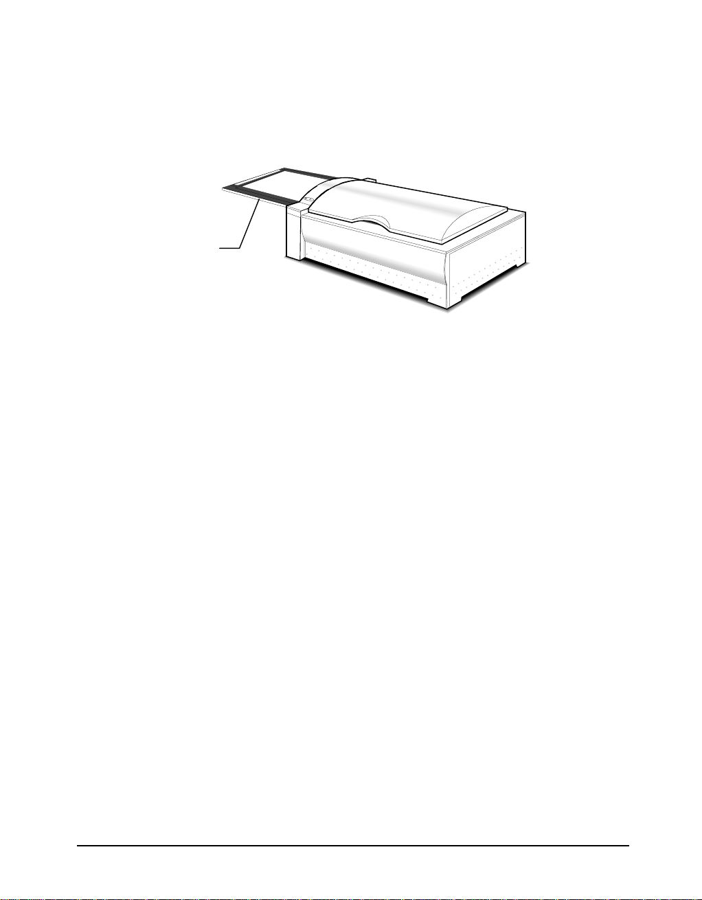
Notice for Scanning Images
PowerLook 3000 uses a special way to scan documents. Instead of moving the
scanner light source back and forth to capture image data, the object glass of the
scanner moves back and forth while the scanner light source remains fixed.
object glass
Please ensure that there is enough surrounding space for the object glass to move
freely in and out of the scanner (more than 350x320mm).
Also, please note that the maximum thickness for the scanned document should be
no more than 5mm. Otherwise, you may discover that jamming occurs.
8

Chapter 3: PC Installation
This chapter describes how you can connect and use the PowerLook 3000scanner
with your IBM PC or compatible computer.
Interface Card Installation
Before you can use your scanner with your computer, you need to install the
interface card into your PC. Please consult paragraphs “A” or “B” below to make the
appropriate settings for your card.
A. If your interface card is a UMAX proprietary card and has I/O Base Address dip
switches on it, refer to the documentation that came with your interface card to
confirm or reset the I/O base address.
B. If your interface card is a switchless card (i.e. does not have dip switches on it for
selecting the I/O base address), install the interface card in the computer as
described in the next section.
To install the card into one of the computer's expansion slots, observe the following
procedures:
Note: The interface card is sensitive to static electricity. Handle the card by its
mounting bracket, particularly when removing the card from its anti-static
packaging.
1. Turn the computer power off and unplug the power cord.
2. Remove the housing cover of the computer. Follow the instructions provided in
your PC’s reference manual.
3. Remove the metal cover corresponding to your chosen slot. Keep the removed
screw so that it can be used to fasten the interface card.
4. Gently insert the interface card into the slot until it is firmly seated in the slot.
5. Secure the card in place with the screw removed from the expansion slot cover
in step 3 above.
9

6. Replace the housing cover following the instructions provided in the computer’s
reference manual.
Connecting the Scanner to the Computer
With settings on the scanner and card correctly set and the interface card properly
installed in your computer, you can now connect the scanner and the computer, as
follows:
1. Connect the 25-pin cable connector to the interface card in the PC.
Note: If your SCSI card is not a UMAX brand, you have to use the other 50-
pin port (50-50 pin) cable connector to connect to your interface card.
2. Connect the other end of the cable to the 50-pin connector of the scanner.
3. Connect the power cord to the scanner.
4. Turn on the scanner power.
5. Turn on the computer power.
Hardware installation is now completed.
Get ready to run the UMAX Setup program to install the supporting UMAX
software supplied with your system.
10

Installing the Software
Install the software in two easy steps, in the following order:
1. Image Application Software, e.g. binuscan PhotoPerfect, Adobe Photoshop.
2. Then, MagicScan.
MagicScan is the interface used by application software to control UMAX scanners.
Its advanced controls allow precise adjustments to images even during the initial
scan.
For detailed information on installing the image editing application software, refer to
the Installation section of the Image Editing Application Software User's Guide.
1. Insert the UMAX MagicScan CD into your CD-ROM drive.
Win95 users
2.
command.
Win3.1 users
Program Manager.
3. In the Command Line of the Run dialog box, type d:\setup (if you are using
CD-ROM drive D). If your CD-ROM drive is designated by another drive,
please type the appropriate letter in the Run dialog box.
4. Follow the on-screen instructions to completely install MagicScan.
- click on the Start button on the taskbar and select the Run
- choose the Run command from the File menu of Windows
Double-click the Read Me icon in the MagicScan group for important up-to-date
information that may not be included in the manual.
11

Scanning with Scan Frames
Scan Frames are for use with transparencies and negatives. Scan Frames are thin,
hinged, rectangular-shaped plastic frames which can hold a source document of a
slightly smaller size. The Scan Frames come in a number of sizes, including 120 mm
and 4 x 5 inch. Orientation holes are located on the short sides of the frames. When
one or more of these frames are placed on the scanner’s object glass and the “Scan”
button is clicked, the scanner will automatically detect the existence of each frame,
using the orientation holes for reference, and will only include what is within each
Scan Frame in the resulting scanned image.
To use the Scan Frames, do the following:
1. Select a Scan Frame size which will hold the original source document without
covering up the orientation holes.
2. Select the “Frame Holder Detection” option from the MagicScan. For detailed
information on using frame holders, refer to your MagicScan Electronic Book.
3. Open the Scan Frame and place the source document inside, taking care not to
cover the orientation holes.
4. Lift up the Scanner’s cover and place the Scan Frame on the scanner’s object
glass.
5. Carefully place the Scan Frame so that it’s exactly parallel with one of the border
of the scanner’s object glass. You can easily do this by simply placing the Scan
Frame against one of the borders.
Note: Although misalignment will not prevent the scanner from scanning, portions
of the Scan Frame may appear in the resulting scan if the frame is not
perfectly aligned.
12
Notice for Scanning Images
PowerLook 3000 uses a special way to scan documents. Instead of moving the
scanner light source back and forth to capture image data, the object glass of the
scanner moves back and forth while the scanner light source remains fixed.
object glass
Please ensure that there is enough surrounding space for the object glass to move
freely in and out of the scanner (more than 350x320mm).
Also, please note that the maximum thickness for the scanned document should be
no more than 5mm. Otherwise, you may discover that jamming occurs.
13

Chapter 4: Troubleshooting Tips
The PowerLook 3000 scanner was designed to provide a hassle-free installation and
operation. However, should you encounter problems with your scanner, correct
them by way of the troubleshooting tips given in this chapter.
For persistent problems with your computer, consult your dealer or approved service
personnel.
General Approach
In most cases, a problem does not call for the service of a qualified technician. The
solution may be very simple, such as correcting cabling connections and the like. The
solution of a problem normally lies at the source of the problem. Therefore, it is
important that you ascertain the cause of the failure or malfunction. Below is a
general troubleshooting approach.
1. Check the connections and installation. Ensure that there are no loose
connections. Ensure that the settings on the scanner and/or the interface card
are correct.
2. Check the error messages appearing on the screen. Does the message point to a
hardware problem or software problem?
If the problem is software-related, refer to the software reference manuals or
on-line help. Most software manuals include a troubleshooting chapter.
If the problem is hardware-related, verify that the cause is from your computer
or scanner or in some cases, your network. If it is due to your computer
malfunctioning, then consult your computer’s reference manuals or a computer
service technician.
Note: Macintosh and IBM computers and compatibles display error messages
that normally tell you the cause of the problem and in some cases tell you
what to check or do to solve the problem.
1. If the error message points to a problem with your scanner system, run the
scanner self-test.
Turn the power of your scanner on. At power on, your scanner automatically
runs the scanner self-test which can detect most of the problems with your
scanner.
Observe the behavior of the LED indicators. Record all your observations.
14

2. If all else fails, call your dealer.
To facilitate servicing, supply your dealer with the following information:
•
Your host environment files such as your config.sys, autoexec.bat, win.ini,
system.ini and other system files
•
Names and version of the application software you are using
•
Model and version of other SCSI devices you are using
•
TWAIN version
•
Names and versions of the drivers you are using
•
Model and version of your scanner hardware
•
Error codes or messages seen
•
Description of what you were doing at the time the malfunction or failure
occurred
•
Description of what you did to attempt to solve the problem
•
Other observations that may aid the technician in identifying the problem
and the solution
LED Indicators
The tables below list some of the more common specific problems you may have
with your scanner. Corrective actions are also given.
Problem 1: Power Indicator fails to come on
Possible Cause / Solution:
!
Make sure the power cable is plugged into the scanner and the wall socket.
!
Make sure that the power switch is on.
!
If none of the above works, contact your dealer.
Problem 2: Scanner lamp flickers, is dim, or fails to come on
Possible Cause / Solution:
!
The scanning lamp is failing or has failed and needs to be changed. Contact your
dealer.
15

Problem 3: If the Power and Ready indicators come on, but software returns
"Scanner link failed" or similar message
Possible Cause / Solution:
!
Make sure the cable is connected properly.
!
Verify the setting of the SCSI ID number. PC users should also pay special
attention to the I/O address setting.
!
Disconnect all SCSI devices and connect them one by one, beginning with the
scanner, to identify the device causing the problem.
!
Check the terminators and the cables. If problem persists, contact your dealer.
System Hang
You may encounter a situation where the PC software installation appears to be
stable and the scanner appears to be normal, but the system “hangs” whenever
scanner operations are attempted. This problem is most often caused by another card
in the system being set to the same address of your interface card. To solve the
problem:
1. Remove all unnecessary interface cards from the PC.
2. If your interface card has I/O address setting dip switches on it, reset the
switches to an unused number (not 300H).
3. Run Windows and your TWAIN-compliant imaging software.
4. Follow the instructions in the imaging software manual to start MagicScan.
5. After MagicScan starts, an initialization file will be automatically written to your
hard disk. When MagicScan starts, exit MagicScan, the imaging application, and
Windows.
6. Turn off the PC and re-install the other cards in your PC.
7. When you reboot and attempt to run MagicScan, it should come up normally.
8. If the above does not solve the problem, consult your dealer.
16
Appendix A: Installing An ASPI-Compatible Card
If you are using an ASPI-compatible SCSI interface card with your computer and
scanner, refer to the installation instructions provided with the interface card.
After installing the card, do the following steps before connecting your scanner to
your computer.
!
Confirm or reset the SCSI address of the scanner.
!
Check the terminators in the SCSI Chain
!
Make the SCSI cable connections.
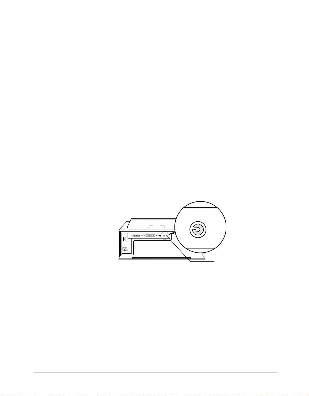
Checking the SCSI Addresses
The illustration below shows the location of the SCSI address selector at the rear
panel of the scanner. The selector shows the SCSI address setting of the scanner. In
this case, it is #5 - the factory preset address.
After installing an ASPI-compatible SCSI interface card in your computer, proceed
with the following:
1. Check the SCSI addresses of all devices on the SCSI chain. Is SCSI address #5
on the list of SCSI addresses in use?
5
SCSI ID
2. If not, then you can connect your computer to the scanner with a factory preset
SCSI ID of 5. You may jump to the section Check the Terminators in this
appendix.
17
Resetting the Address of the Scanner
If SCSI address #5 is in the list of SCSI addresses in use, then you must reset the
SCSI address selector to another number:
1. Ensure the scanner power is off.
2. Choose any unused number in the range 0-6.
Note: Do not use settings 7 to F on your scanner. They are for factory use only.
3. Reset the scanner’s SCSI address to the number you have chosen.
Checking the Terminators
There should be two terminators in a SCSI chain: it is best to place the terminators at
each end of the SCSI chain.
The simplest configurations for using the scanner with an ASPI compatible SCSI
card are as follows:
!
Connect the scanner to an ASPI compatible interface card that does not have
another device attached to it.
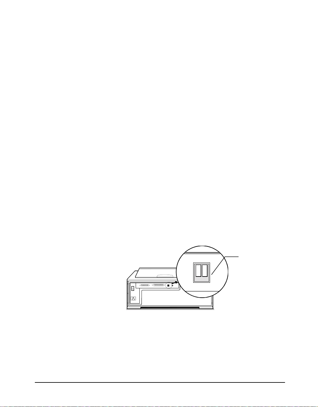
PowerLook 3000 has a built-in terminator switch for you to turn on and off (see
the illustration). Number 1 represents “active” and number 2 represents
“terminator power”. In this situation, the card will have a built-in terminator.
The card forms one end of the SCSI chain; the scanner forms the other end.
Simply turn on the “active” and “terminator power” switch by pressing them
down to enable the built-in active terminator function. These will ensure that
there are two terminators and that they are placed at the ends of the SCSI chain.
Terminator Switch
12
!
Connect the scanner to an ASPI card that has another device attached to it.
In this case, check to see if the other SCSI device has a terminator. If not, turn
on the terminator switch. If the other device has an internal terminator, simply
attach the scanner to the SCSI chain. Although the terminators are not,
technically speaking, placed at the ends of the chain, the scanner should work
properly.
18
If you experience unreliable SCSI operation and suspect terminator problems, or
would like a more thorough discussion of SCSI terminators and possible problems
with SCSI terminators, please consult your dealer.
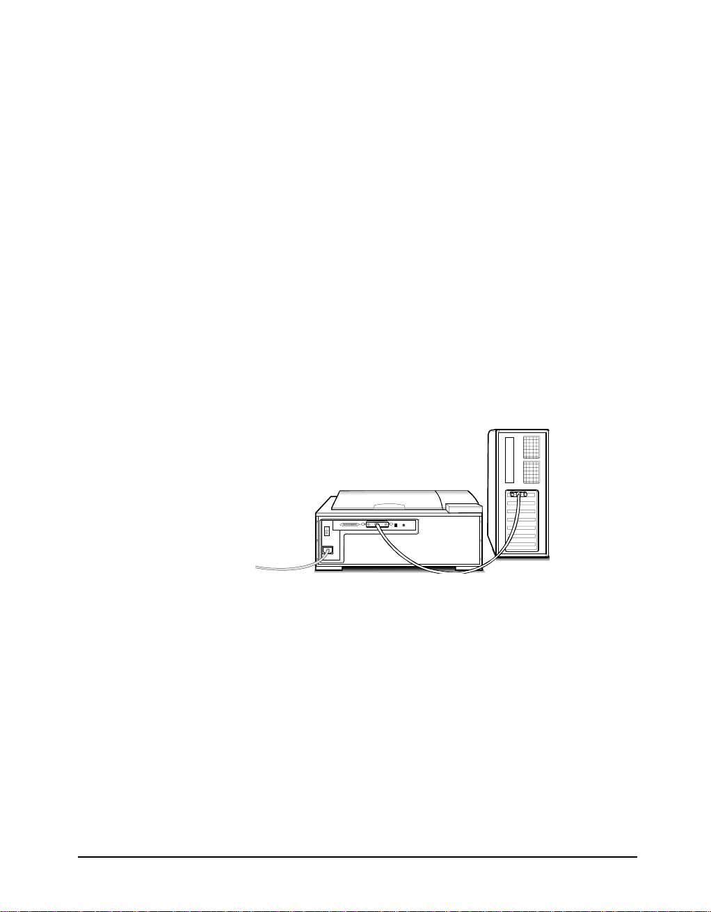
Connecting the Computer and Scanner
Now that the interface card has been installed and all of the settings on the scanner
and card are properly set, you can connect the computer and the scanner. Once this
has been done, the hardware installation will be complete. To connect the scanner
and computer, do the following:
1. Connect the SCSI cable to the interface card.
2. If your SCSI configuration requires the use of the terminator, turn on the
terminator switch.
3. Connect the other end of the SCSI cable to the scanner.
4. Connect the power cord to the scanner.
5. Turn on the scanner power.
6. Turn on your computer power.
Installing the Software for PC Users
Install software in two easy steps, in the following order:
1. Image Application Software.
2. MagicScan
MagicScan is the interface used by the application software to control UMAX
scanners. Its advanced controls allow precise adjustments in images even during the
initial scan.
For detailed information on installing the image editing application software, refer to
the Installation section of the Image Editing Application Software User's Guide.
1. Insert UMAX MagicScan CD into your CD-ROM drive.
19

Win95 users
2.
- click on the Start button on the taskbar and select the Run
command.
Win3.1 users
- choose the Run command from the File menu of Windows
Program Manager.
3. In the Command Line of the Run dialog box, type d:\setup (if you are using
CD-ROM drive D). If your CD-ROM drive is designated by another drive,
please type the appropriate letter in the Run dialog box.
4. Follow the on-screen instructions to completely install MagicScan.
Double-click the ReadMe icon in the MagicScan group for important up-to-date
information that may not be included in the manual.
20

Appendix B: Scanner Specifications
Scanner Type
Interface
Scan Speed
Maximum Scannable Area
Optical Resolution
Output (H/W) Resolution
Maximum Resolution
Color Scanning Method
Sample Depth
Color Mode 24/36 bits/pixel
GrayScale Mode 8/12 bits/pixel
Lineart mode 1 bit per pixel
Scanner Settings
Scaling 1% to 1000%/400% in 1% increments at 1220/ 3048 dpi resolution
Highlight/Shadow 256 steps
Contrast/Brightness -100% ~ +100%
Gamma Curve Downloadable Curves
Data Output
Color Mode 42 bits (hardware) /24 bits (system)
Grayscale Mode 14 bits (hardware) /8 bits (system)
Power Requirements
Voltage 100 ~ 240 VAC
Frequency 47-63Hz
Power Consumption Maximum 60 Watts
Environmental Range
Operating Temperature 5°C ~ 400°C (50°F ~ 750°F)
Relative Humidit y 25% ~ 85%
Other Specifications
Noise Under 60 dB (Operating)
Dimensions 548 mm x 425 mm x 219 mm
Net Weight 18.5Kgs (40.7lbs)
Systems Supported PC and Macintosh computers
Note: Specifications are subject to change without prior notice.
Moving Flatbed
Built-in SCSI II, 25-pin and 50-pin connectors
205 sec. (1220dpi) in color mo de
514 sec. (3048dpi) in color mo de
Low power lens : 8.5” x 11.7”
High power lens: 3.4” x 11.7”
1220 x 3048 dpi / 3048 x 3048 dpi
1220 x 3048 dpi / 3048 x 3048 dpi
12192 x 12192dpi
One pass with color CCD
21

Glossary
Apple Compatible Driver
Application Software
ASPI
Black and White
DIP Switch
Expansion Slot
Expansion Slot Cover
Folder
Grayscale
Halftone Pattern
An interface software module for applications other than Photoshop that
support Apple scanners.
Software that is used to pe rform a specific function, e.g., image processing,
OCR (Optical Characte r Recognition), or DTP (Desktop Publishing).
SCSI communication standard developed by Adaptec.
A 1-bit image file capable of d i splaying only black and white image d ata
with no intermediate gray levels.
A small switch mounted in or on computer equipment that sets certain
parameters.
A connector and bracket system in a computer into which an expansion or
interface card can be inserted to add functions to a computer system.
A metal or plastic plate dust cover that covers the exterior "hole" of an
expansion slot.
The icon in Macintosh systems in which sof tware icons can be placed.
An 8-bit image file capable of displaying up to 256 gray levels.
The pattern that is used when varying the ratio of black and white pixels in
a halftone image.
Halftone
I/O Base Address
Icon
Indicator Panel
Interface Card
Non-TWAIN Driver
A 1-bit image file capable of displaying gray levels by va rying the ratio of
black and white pixels within a given area.
An address that is used for communication between a host computer and
an expansion or interface card. All cards in a computer system must be set
to different I/O addresses.
The graphical representation of a computer file or piece of computer
software.
The area of the scanner that holds and displays the LED indicators.
A card that provides additional functions or capabilities for your computer .
These cards are called by various names such as adapter, add-in card,
controller card, e x pansion card, option card or by the names of the
functions they do such as f ax/modem cards, networ k card, scanner ca rd,
etc. This card is inserted into an expansion slot to allow the connec tion of a
peripheral device to a PC.
An interface system that does not follow the TWAIN standard and is
designed for a specific software package and a specific image input device.
22

Object Glass
The tempered glass of the scanner where documents or object to be
scanned are placed.
Optical Assembly
Peripheral Device
Power Indicator
Ready Indicator
SCSI Chain
SCSI Device
SCSI ID
SCSI ID Switch
Terminator
TWAIN
The component system of the scanner that contains all the scanner's
optical components. Sometimes referred to as a carriage or carriage
assembly.
A device attached to a computer that adds functions to a computer system.
The indicator that glows when the scanner's power cable is connected to
the scanner and "live" outlet and the power switch is turned on.
The indicator that glows when the scanner is ready to be used.
One or more SCSI devices connected to the same SCSI controller.
A device that uses the SCSI interface to connect to a computer.
A unique number between 0 and 7 that identifies each device in a SCSI
chain. The SCSI ID is set using a SCSI ID switch found on most external
SCSI devices.
The switch on most external SCSI devices which is used to set the SCSI
ID.
An electronic component that absorbs stray signals in a chain of computer
equipment to ensure reliable operation.
A standardized interfacing system that allows many different software
applications to access many different image input devices.
TWAIN Compliant
Any software or image inpu t device that conforms to the TWAIN
standard.
23
 Loading...