

Page 1
AIR DISINFECTION SYSTEMS
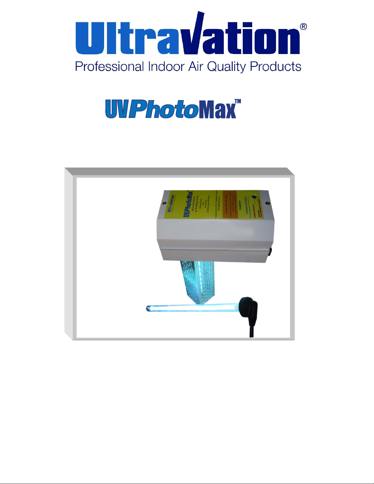
OWNERS GUIDE
Table of Contents:
Page 2 – Shipping and Packing List, Safety Precautions, Warranty
Page 3 – Installation Steps, Installation Steps for UVViewport, Maintenance, Lamp Replacement, Reset Service Indicator
Page 4 – Adjusting Your Advanced Photo Catalytic Air Cleaner, UVLampMonitor Status Table, Replacement Parts
LEAVE FOR HOMEOWNER
DC-IH-0234
Page 2

Shipping and Packaging List:
UV PhotoMax Electrical Housing
4- ¾ inch 5/16 self tapping sheet metal screws
UVC Warning Label
Warranty Card
Remote mount Viewport Label
Remote mount Viewport / Sight Stick
One 12” Photo catalyst oxidation lamp
18” Sealing Gasket
Two Wire Nuts (for 24V systems)
40 VA multi-tap transformer (for 24V systems)
Duct board mounting plate
Safety Precautions:
It is recommended that this unit be installed and
maintained by a trained technician:
WARNING: UV Hazard. Always protect eyes from
ultraviolet light. NEVER look at UV lamps in
operation. Unplug or disconnect power before relamping or servicing.
WARNING: Severe eye damage or temporary
blinding may occur.
WARNING: DO NOT operate outside of Air Handler.
Mount product to duct first.
WARNING: No openings in duct are allowed which
would give direct line-of-sight to the UV light.
In the event of accidental breakage or replacement of
the ultraviolet lamp, please ensure that the lamp is
disposed of in accordance with local and state
environmental laws regarding fluorescent lamps
containing mercury.
Notice:
All wiring inside of the duct or air handling system in
direct line of site of the UV lamp must be shielded with
aluminum foil tape or equivalent non-combustible
material. When installing this unit, select a mounting
location that prevents ultraviolet light exposure to
plastic flexible duct liner or other plastic components
with unknown resistance to ultraviolet light. Ultraviolet
light may cause color shift or structural degradation of
plastic HVAC components
Warranty:
Ultravation warrants this product against any
defects in material or workmanship for a period of
10 years after date of consumer purchase, with
the exception of the Ultraviolet Lamp, which is
warranted for a period of one year after date of
consumer purchase.
This warranty does not include damage to the unit
from accident, misuse or improper installation.
If this product should become defective during the
warranty period, Ultravation will elect to repair or
replace the product free of charge.
Ultravation will return repaired or replaced
warranted products pre-paid, provided that the
product was delivered pre-paid. Ultravation shall
have no responsibilities for charges incurred by
the customer for installation or removal of
warranted items. Liability is limited only to the
replacement or repair of this product
This warranty gives you specific legal rights, and
you may also have other rights, which vary from
state to state.
All returns must be accompanied by a return
authorization number, which may be obtained by
contacting Ultravation, Inc.
Ultravation, Inc. ~ P.O. Box 165 ~ 212 Ideal Way
~ Poultney, Vermont 05764
Phone: 866-468-8247 ~ Fax: 802-287-9203 ~
www.ultravation.com
www.ultravation.com
2
Page 3

Installation steps:
1. Mounting holes are located on the outside flange;
additional support can be acquired by using the
larger mounting plate.
2. Determine a suitable location to install unit
housing. Mounting location should be of sufficient
strength as to support the unit; otherwise
reinforcement of the ductwork may be necessary.
3. Using the supplied template cut the hole needed
for the insertion of the advanced photo catalytic
chamber.
4. Lift into place against ductwork. Fasten unit in
place with four self- tapping screws (supplied).
5. The unit ships with the lamp in place. Remove
6. Adjust the air cleaner per the directions on the
7. Put cover back on unit.
8. Plug unit in and inspect operation (For 24VAC
Note: The UV lamp can be removed
independently, simply by removing the 2 screws
in the lamp holder.
Note: the pins are in a rectangular pattern and can
only be mated in 2 positions.
Installation Steps for UV Viewport:
1. Find a location on the air handler or ductwork that
will visible and be in direct line of site of UVC light.
2. Affix UV Viewport label to air handler or ductwork.
3. Drill a 3/8” hole through label and air handler or
ductwork in marked location on label.
or push the duct board sight stick into duct board.
4. Press in UV Viewport until it snaps into place (not
used with duct board sight stick).
cover to make sure the connector is seated on the
lamp base.
next page (as indicated under the cover.
units the unit is to be hard wired using the
supplied 24VAC transformer.)
Maintenance:
Typical maintenance of the PhotoMax system is
recommended replacement of the Dual Spectrum
Lamp every 2 years and replacement of the PCO
Module is every 5 years.
UV lamps undergo a photochemical process
during operation. This slowly reduces the amount
of UV light generated to disinfect against airborne
pathogens.
When installing new lamps, ensure that the lamp
glass is free from any fingerprints or debris, as
this may alter the path of the UV energy. Use
rubbing alcohol and a dry cloth to remove any
surface contaminants.
Lamp Replacement:
The UV Lamp is shipped installed in the
equipment. However annual replacement is
required for airstream disinfection. To replace the
UV Lamp follow the steps below:
1. Turn power off and remove cover.
2. Pull advanced photo catalytic rod to its
full out position.
3. Unplug lamp and remove screws.
4. Change lamp and connect lamp.
5. Readjust the advanced photo catalytic
control.
Reset your Service Indicator
1. To set or reset the annual service
indicator the unit must have power to it.
2. Press down and hold the square yellow
RESET button (hold down for 10 sec.) on
circuit board (located below LED view
port on the end of the electrical housing),
the LED should turn GREEN while the
button is depressed.
3. Release the square yellow RESET
button.
4. LED should be Green.
For optimum 24/7 air stream disinfection it is
recommend the UV-C lamp is replaced on an
annual basis.
www.ultravation.com
3
Page 4

Adjusting Your Advanced Photo Catalytic Air Cleaner:
The UV PhotoMax equipment has a patented design to be a universal air cleaner with adjustability to the advanced
photo catalytic process for a variety of sizes for treated space. When setting up your equipment, adjust the Advanced
Photo Catalytic control knob ( under electronics cover)to the appropriate position based on the squ are foota ge of the
home .
Fine adjustments may be required depending upon household living characteristics.
For more information please call Ultravation : 1866-468-8247 ext 16- Customer support.
UVLampMonitor Status Table:
LED
Color
Green
Solid Red
Flashing Red
(Every 5 seconds)
Audible
Visual Alarm
No audible
No Audible
Beep every
3 Minutes
Unit
Status
OK
Reset lamp service indicator or replace lamp within 30 days
Occurs at approx. 11 months of operation
Lamp has exceeded 1 year of operation, reset or replace lamps
Pulsing Red
(Every 1 second)
Beep every 1
second
UV lamp(s) are not lit (verify if possible)
Upgrade for object purification:
This product may be upgraded to power a single 12" or 17" Ultravation T3 lamp.
This may be necessary especially in the southern most states or where there is a constant demand for Air conditioning as
this practice tends to lead to bacterial fouling of AC equipment.
In some cases it may be necessary to have a 3rd dedicated lamp for items such as blower motor assemblies or turning
vanes.
Upgrades should be done by a trained technician only.
Consult your HVAC technician or call 1-866-468-8247 for more information.
Replacement Parts:
Model
Description Replacement Part
Number
Lamp 12” oxidation Lamp ASIH1013
PCO Module 12” Advanced Photo
94-056
Catalytic Module
www.ultravation.com
4
 Loading...