

Page 1
DC-OH-0224 REV A
Homeowner / User Guide
UMX-2412-EZ
UMX-2419-EZ
UMX-12012-EZ
1-866-GO-UV-AIR (468-8247)
UMX-12019-EZ
UMX-24012-EZ
UMX-24019-EZ
ultravation.com
OPEN >>>>
Thank you for purchasing an Ultravation
®
Professional Indoor Air Quality Product
The UltraMAX™ EZUV
We recommend that this unit be installed and maintained by a trained HVAC professional technician.
Installation steps for external mounting of power supply:
1. Determine a suitable location to install unit housing. Mounting location should be of
sufficient strength as to support the unit, otherwise reinforcement of the ductwork
may be necessary. Fasten the unit in place with two self-tapping screws (supplied).
2. Select location for UV lamp module. Drill a 1" hole. Mount mounting plate over
drilled hole with screws provided. Insert UV lamp module into hole. Attach to HVAC
system with two self-tapping screws (supplied).
3. Plug the rubber lamp connector fully onto the installed UV lamp assembly. Be sure
the four pinholes are orientated properly to the four matching pins on the lamp (see
other side of this manual).
4. Connect power wires to a dedicated minimum 40VA transformer or hardwire to
appropriate voltage based on requirements listed on power supply label. This should
be done in accordance with all state and local electrical and building codes.
Notes: The UV lamp assembly can be removed independently, by removing the
two screws in the lamp holder.
The rectangular pin pattern allows connection in two positions (see other
side of this manual).
A UV status viewport lens is supplied to verify lamp operation. Drill a 3/8"
hole within a 3" radius around the lamp, and on the “lamp side” of the “V”
in the light shield to accommodate installation of the viewport.
Important information about UV lamp replacements
Replace UV lamps each year in order to maintain optimum effectiveness in the reduction of pathogens such as bacteria, viruses and microscopic mold. Lamps operating
after a period of two years do not provide adequate reduction of pathogens and must
be replaced. Lamps operating beyond 18,000 hours (two years) draw excessive electrical current which may result in damage to the UV system. If UV lamp(s) have been
operating for more than two years, the system must be turned off until replacement
lamp(s) are installed. Failure to do so may void the warranty.
Installation Steps for Internal Mounting of Power Supply:
1. Mount power supply inside of the air handler but out of the air stream as much as
possible. Place the power supply close to the control panel for ease of connecting
to 24 VAC or appropriate voltage according to the power supply label.
2. To utilize the internal mounting bracket, first install the bracket inside the air handler
in a location that will position the UV lamp such that it bathes the entire surface to
be treated. Plug the lamp connector onto the lamp and snap into the bracket.
Note: The rectangular pin pattern can be mated in two positions only.
3. Connect power wires to a dedicated minimum 40VA transformer. This must be
done in accordance with all state and local electrical and building codes.
Maintenance
Never perform maintenance on the UV unit without disconnecting power. Typical
maintenance consists of replacement of the ultraviolet (UV) lamps. UV lamps undergo a
photochemical process during operation. This slowly reduces the amount of UV light
generated to disinfect the air and surfaces. For optimum air stream disinfection UV
lamps should be replaced on an annual basis. For surface disinfection, lamp replacement should be performed no later than every two years (see above, “Important
Information about UV lamp replacements”).
When installing new lamps, ensure that the lamp glass is free from any fingerprints or
debris, as this may alter the path of the UV energy. Use rubbing alcohol and a dry cloth
to remove any surface contamination.
See Lamp Replacement Safety Reset)
(
SAFETY PRECAUTIONS:
It is recommended that this unit be installed and maintained by a trained technician:
WARNING: UV Hazard. Always protect eyes from ultraviolet light.
NEVER look at UV lamps in operation. Unplug or disconnect power before
re-lamping or servicing.
WARNING: Severe eye damage or temporary blinding may occur.
WARNING: DO NOT operate outside of air handler. Mount lamp base to
duct first.
WARNING: No openings in HVAC system are allowed which would give
direct line-of-sight to the UV light.
In the event of accidental breakage or replacement of the ultraviolet lamp, please
ensure that the lamp is disposed of in accordance with local and state environmental
laws regarding fluorescent lamps containing mercury.
Notice: All wiring inside air handling system in direct line of site of the UV lamp must
be shielded with aluminum foil tape or equivalent non-combustible material. When
installing this unit, select a mounting location that prevents ultraviolet light exposure to
plastic non UV-rated flexible duct liner or other plastic components with unknown
resistance to ultraviolet light. Ultraviolet light may cause color shift or structural
degradation of plastic HVAC components. If installing where UV light can directly
contact fiberglass duct board, contact manufacturer of fiberglass product for advice
on UV rating. If unknown, install metal sheathing or foil tape to completely protect
fiberglass duct board from UV light exposure.
LAMP REPLACEMENT SAFETY RESET
Disconnecting power is required for lamp replacement. NEW lamps will not light if
power has not been disconnected. Power must be off for at least FIVE seconds.
UL Listed. The health aspects associated with the use of this product and its ability to aid in disinfection of environmental
air have not been investigated by UL.
Troubleshooting
Ultravation® air disinfection equipment is designed to provide many years of trouble
free operation. In the unlikely event of a problem, please contact your local HVAC
professional or Ultravation directly. Before calling for service, you should have the
model number, serial number, and purchase date.
If you are troubleshooting the unit, please check the following:
• Verify if in fact the UV lamps are on or off (never look at a UV lamp in operation, you
can safely confirm operation by way of the UV viewport installed with the unit).
• Verify the unit has power. Check voltage requirement on power supply label and
confirm proper power is supplied.
• If you have an inline fuse verify that the surge protection fuse is still functional. If
necessary, replace with a 1 to 2 AMP maximum AGC type fuse.
• Be sure lamps are securely plugged into their sockets, no loose wires, and in the
correct orientation (see other side of this manual).
• If possible install a new lamp to determine whether the problem is the lamp or the
power supply.
Remember: DO NOT look at UV light without proper eye protection.
REPLACEMENT PARTS AND ACCESSORIES
12" T3 UVC Lamp .............................................................................. AS-IH-1001
17" T3 UVC Lamp .............................................................................. AS-IH-1003
Light Shield ......................................................................................... 94-010
Optional PCO plate ............................................................................ 94-004
Warranty
Ultravation warrants this product against any defects in the UVC lamp power supply
for a period of ten years after date of consumer purchase, with the exception of the
ultraviolet lamp, which is warranted for a period of one year after date of consumer
purchase.
This warranty does not include damage to the unit from accident, misuse or improper
installation. If this product should become defective during the warranty period,
Ultravation will repair or elect to replace the product free of charge.
Ultravation will return repaired or replaced warranted products pre-paid, provided that
the product was delivered pre-paid. Ultravation shall have no responsibilities for
charges incurred by the customer for installation or removal of warranted items.
Liability is limited only to the replacement or repair of this product.
This warranty gives you specific legal rights, and you may also have other rights, which
vary from state to state. All returns must be accompanied by a return authorization
number, which may be obtained by contacting Ultravation, Inc.
Ultravation, Inc.
P.O. Box 165, 212 Ideal Way, Poultney, Vermont 05764
Phone: 1-866-GO-UV-AIR (468-8247) • Fax: 802-287-9203
www.ultravation.com • info@ultravation.com
Copyright © 2008-2013 Ultravation Inc.
Ultravation.com
Page 2
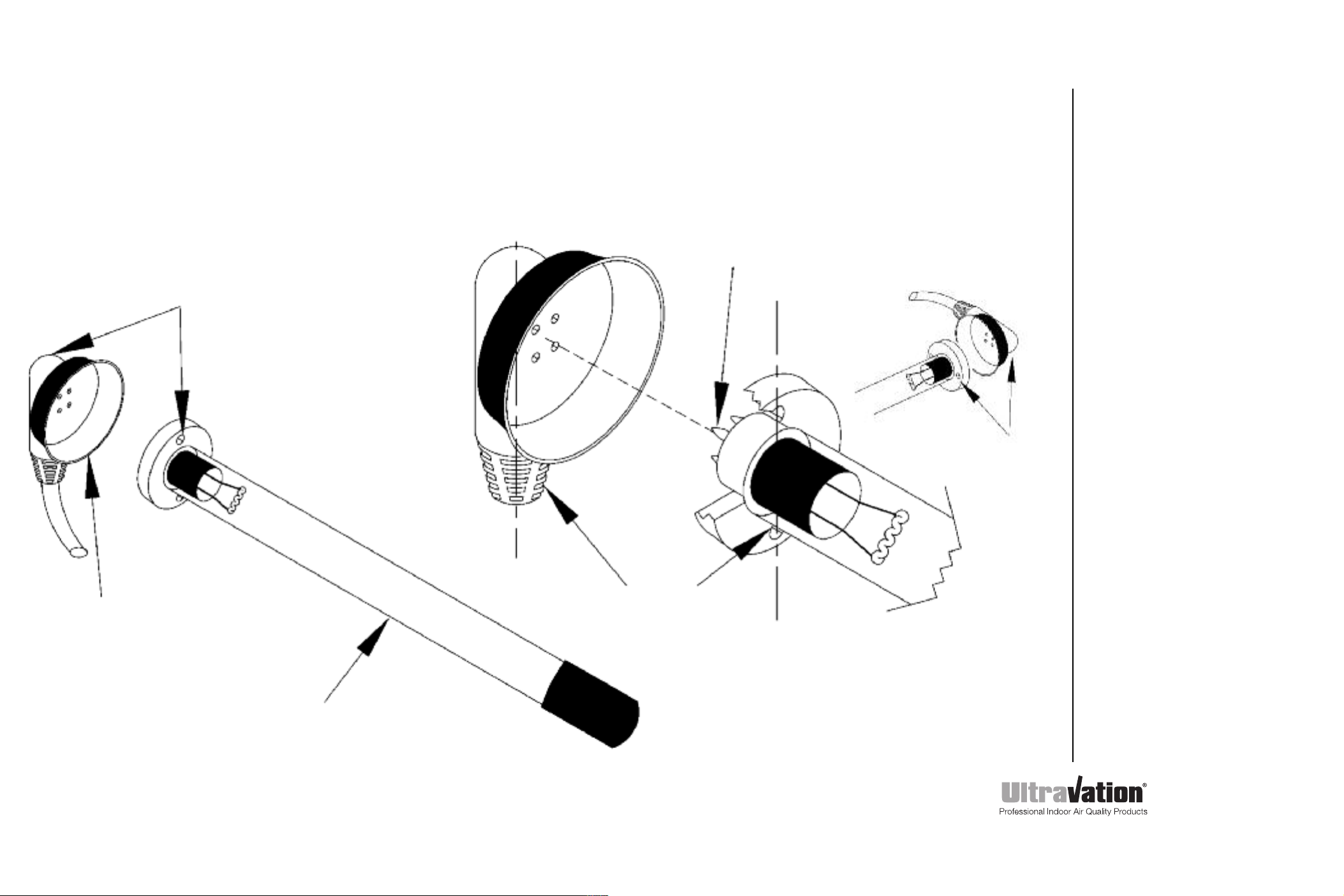
Important!
Electrical
Read before installation
The screw holes on the UV Lamp
need to be parallel to the Lamp Lead
cord on the back of the female
receptacle for correct assembly!
Note that lamp pin
pattern is NOT square.
It can be mounted from either side
and top or bottom depending on
the orientation of the installed lamp.
Horizontal orientation of
the lamp lead requires
installing the lamp with
screws left to right.
NOTICE: All 24 volt UV
equipment for HVAC
systems (regardless or
manufacturer) must be
installed using a separate,
dedicated minimum 40VA
transformer to avoid the
possibilty of voiding UL
certification of the HVAC
system.
IMPORTANT: Some EZUV
models are equipped with an
in-line fuse for both surge
and electrical arc protection.
Replace only with equal
value fuse (available from
Ultravation or authorized
distributor, part number
EL-PP-0001).
Failure to do so will defeat
the design and void the
warranty.
Lamp Lead (rubber
sleeved female
receptacle)
Lamp screw holes and Lamp Lead
cord need to be parallel
UVC Lamp
Ultravation.com
DC-OH-0224 REV A
 Loading...