

Page 1
2
T
hank you for purchasing an Ultravation
®
Professional Indoor Air Quality Product
•Steel electrical housing
•Mounting plate / PCO module
•4- 3/4 inch 5/16 self tapping
sheet metal screws
•UVC warning label
•Warranty card
•Remote mount viewport label
•Remote mount viewport / sight
stick
•One 12" photocatalyst oxidation
Dual Spectrum UV lamp
•Sealing Gasket
•Two wire nuts
•40 VAC multi-tap transformer
P
ackage Contents:
Introduction
T
he Ultravation
®
U
VPhotoMAX
™
f
or HVAC is a unique air quality improvement
d
evice that uses a photocatalytic (PCO) process to treat the air for organics
f
rom microorganisms to allergens to odors.
The UVPhotoMAX will be effective when used in structures up to 5,000 sq. ft.
Homeowner / User Guide
UVPhotoMAX
ª
1-866-GO-UV-AIR (468-8247)
ultravation.com
DC-OH-0234M R1013
A
dvanced Oxidation Photocatalytic
Whole House Air Purifier
F
or HVAC systems
PTX-1200F
(shown with EZ-Light™ option)
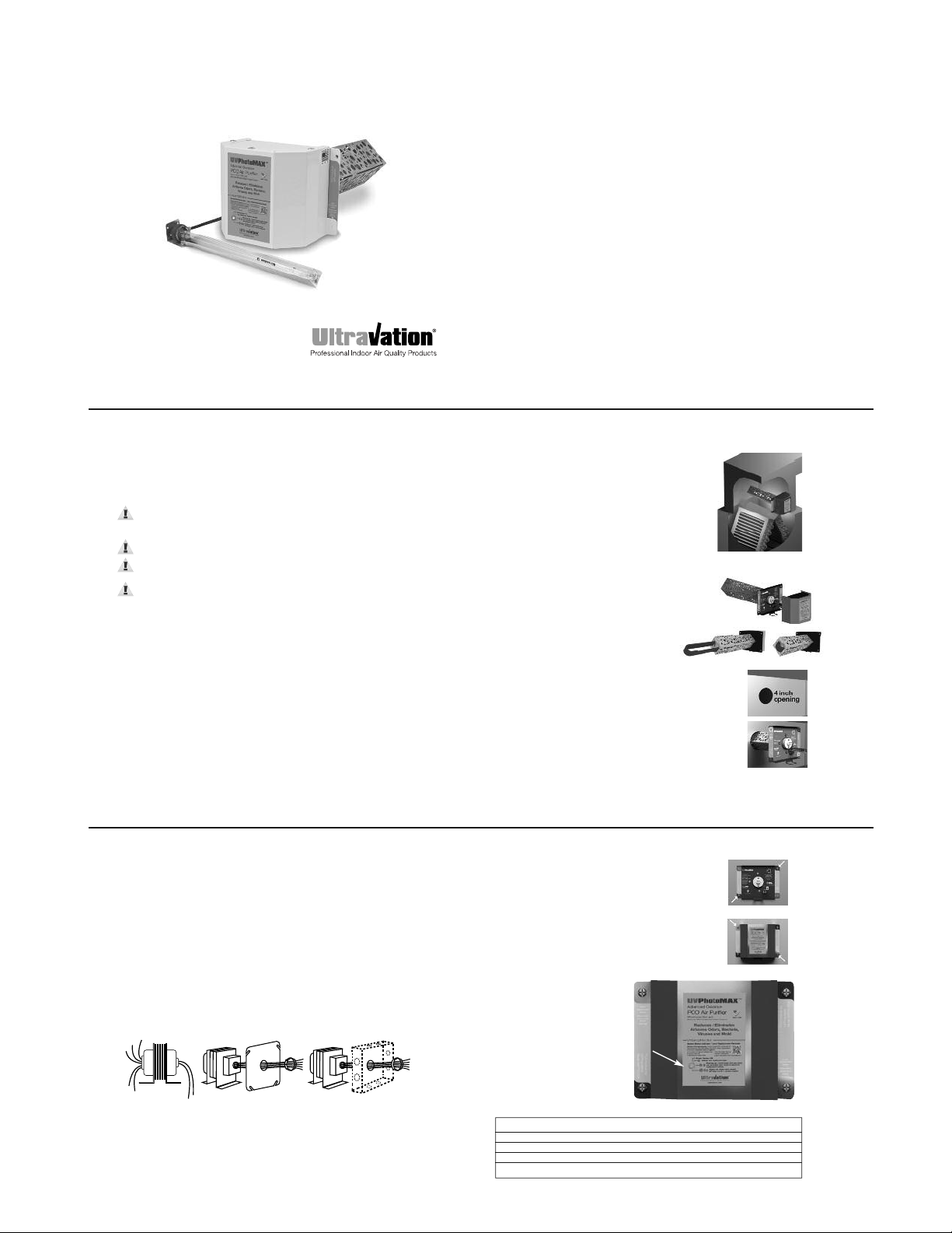
4
1
. Determine a location for the UVPhotoMAX.
Mount the unit on the exit
or supply side of the HVAC system and
before the ductwork branches off.
2. Separate the power module from the
mounting plate. See Fig. 1.
3
.Remove blue lamp protector. See Fig. 2.
4. Mark a 4" round opening (or use the
end of the PCO chamber to mark the
a
rea) on the air duct and cut the hole
needed for the insertion of the
advanced photocatalytic chamber.
See Fig. 3.
5. Thread supplied gasket over PCO module
and attach to mounting plate. (Seals against
air duct.)
6. Insert the mounting plate / PCO module into
opening and attach to duct with two supplied self
tapping screws in the lower left and upper right
(only). See Figs. 4 and 5.
Typical placement in
HVAC system
Fig. 3
F
ig. 1
Installing the UVPhotoMAX
™
F
ig. 2
Fig. 4
3
S
AFETY PRECAUTIONS:
It is recommended that this unit be installed and maintained by a trained
technician:
W
ARNING: UV Hazard. Always protect eyes from ultraviolet light.
N
EVER look at UV lamps in operation. Unplug or disconnect power
b
efore replacing lamps or servicing.
WARNING: Severe eye damage or temporary blinding may occur.
WARNING: DO NOT operate outside of air handler. Operate only
after installed.
WARNING: No openings in HVAC system are allowed which would
give direct line-of-sight to the UV light.
In the event of accidental breakage or replacement of the ultraviolet lamp,
please ensure that the lamp is disposed of in accordance with local and state
environmental laws regarding fluorescent lamps containing mercury.
Notice: All wiring inside air handling system in direct line of site of the UV
lamp must be shielded with aluminum foil tape or equivalent non-combustible
material. When installing this unit, select a mounting location that prevents
ultraviolet light exposure to plastic non UV-rated flexible duct liner or
other plastic components with unknown resistance to ultraviolet light.
Ultraviolet light may cause color shift or structural degradation of plastic
HVAC components. If installing where UV light can directly contact fiberglass
duct board, contact manufacturer of fiberglass product for advice on UV
rating. If unknown, install metal sheathing or foil tape to completely protect
fiberglass duct board from UV light exposure.
7. Adjust Photon Clarifier. See page 7.
8. Place the power module on the unit aligning holes
in tabs with holes in mounting plate (upper left /
lower right). See Fig. 6.
9. Secure the power module to the mounting plate with
the remaining two self-tapping screws.
10. Plug power cable in.
5
Fig. 5
Fig. 6
LED Audible Alarm Unit Status
Green No Sound Normal
Flashing red 3 Min beep One year use exceeded
Pulsing red 1 sec beep Lamp out, service required
Steady Red No Sound Replace lamp(s)
UVLampMonitor Status
Your UVPhotoMAX is equipped
with an electronic power supply
that monitors operation and
protects the UV lamp filaments.
It also monitors elapsed time and
reminds after 9000 hours of
operation that lamps need to be
replaced. Below is a chart that
describes how to interpret
the display.
6
24VAC Transformer
1. Disconnect power supply before beginning installation to prevent
electrical shock or equipment damage.
2. Connect secondary voltage. Refer to voltage color or terminal coding on
transformer for proper wire combination. On terminal type transformer, be
sure that no exposed wire can come in contact with any terminal.
3. Connect primary voltage. Refer to voltage color coding on transformer for
proper wire combination. See Fig. 1 for connection and installation.
4. Tape or protect all unused exposed wire separately to avoid a possible
electrical short.
5. Check installation and reconnect power supply for proper operation.
Common
120
208
240
277
VAC
24 VAC
Fig. 1 Connect power to proper line voltage
Fuse
Some models are equipped with an in-line fuse. If necessary, replace with an
AGC type fuse, 2 AMP MAXIMUM.
Page 2
8
Model Description Replacement Part Number
PCO Lamp 12" Dual Spectrum Lamp AS-IH-1013
PCO Module Replacement base 94-201
EZ-Light 12" UVC Lamp AS-IH-1001
EZ-Light 17" UVC Lamp AS-IH-1003
Replacement Parts
Maintenance
Typical maintenance of the UVPhotoMAX™ system includes recommended
annual service and the replacement of the Dual Spectrum UV Lamp. UV
lamps undergo a photochemical process during operation that slowly
reduces the amount of germicidal UV light generated.
W
hen installing new lamps, ensure that the lamp glass is free from any
fingerprints or debris, as this may alter the path of the UV energy. Use
rubbing alcohol and a dry cloth to remove any surface contaminants.
7
A
djusting the Photon Clarifier
The UVPhotoMAX™ is a universal air
purifier with a patented design that provides
adjustability to the advanced photocatalytic
process for a variety of treated space sizes.
When setting up your equipment, adjust the
Photon Clarifier Adjuster (under electronics
cover) to the appropriate position based on
the square footage of the home or CFM of
t
he air handler.
F
ine adjustments may be required
depending upon household living characteristics.
For more information please call Ultravation Customer support at
1-866-468-8247.
500
1000
2
000
2500
3000
3
500
4000
4500
5000
10000
6000
7000
8
000
9000
2
000
4000
5
000
3000
1000
CFM
Sq. Ft.
P
hoton Clarifier
A
djustment
S
ervice Indicator Reset
1. To set or reset the Bi-Annual Service Indicator the unit
must be connected and have power.
2. Press and hold the square yellow RESET button for 10
seconds using a non-metallic implement. The LED should
turn blue while the button is depressed.
3. Release the RESET button, and the LED will return to
green status.
10
EZ-Light™ UV Option
A UVPhotoMAX™ is capable of powering an optional single Ultravation®T3™
Germicidal UV lamp to keep HVAC internal surfaces clear of mold which reduces airborne mold allergen and helps minimize HVAC energy consumption.
The EZ-Light™ option may be advisable in the southern regions or where
there is a constant demand for air conditioning. Heavier use frequently leads
to bacterial/mold fouling of AC equipment. In these cases it may be beneficial
to add a 3rd lamp for items such as blower motor assemblies or turning vanes.
Stand-alone Ultravation®UltraMAX™ Germicidal UV light kits are available.
We recommend that this unit be installed and maintained by a trained HVAC
p
rofessional technician. Consult your HVAC service provider or call 1-866-468-8247
for more information.
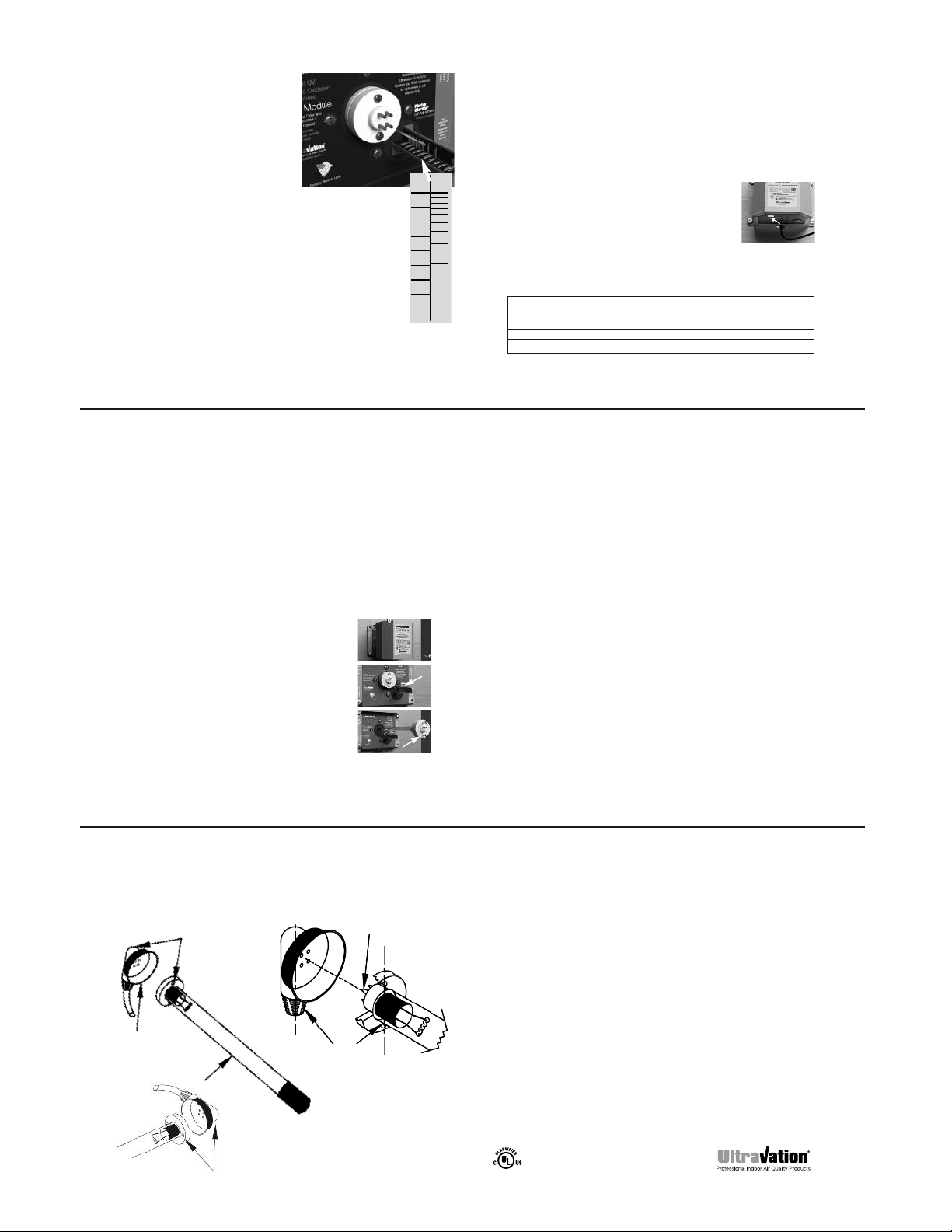
Installation Steps (If EZ-Light was purchased separately see instruction
for connection to UVPhotoMAX accompanying EZ-Light.)
1. Select location for UV lamp. Drill a 1" hole. Install mounting plate over
drilled hole with the provided screws. Insert UV lamp module into hole.
Attach to HVAC system with two provided self-tapping screws.
2. Plug the rubber lamp connector fully onto the installed UV lamp assembly.
Be sure the four pinholes are oriented to match the four pins on the lamp
(see diagram pg. 11).
N
otes:
The rectangular pin pattern allows connection in two positions (see diagram pg. 11).
A UV status viewport lens is supplied to verify lamp operation. Drill a 3/8" hole within a 3"
radius around the lamp, and on the “lamp side” of the “V” in the light shield (if used), to
accommodate installation of the viewport.
9
Lamp Replacement
The UV lamp is shipped installed in the equipment and should be replaced
during an annual service. To replace the UV Lamp follow the steps below:
I
mportant Information About UV Lamp Replacements
Replace UV lamps at each annual service in order to maintain optimum
effectiveness in the reduction of pathogens such as bacteria, viruses and
microscopic mold. Lamps operating beyond one year do not provide
a
dequate reduction of pathogens and must be replaced. Lamps operating
beyond two years draw excessive electrical current which may result in
damage to the UV system. If UV lamp(s) have been operating for more than
two years, the system must be turned off until replacement lamp(s) are
installed. Failure to do so may void the warranty.
1. Unplug power cord
and remove power
module. See Fig. 1.
2. Note the position of
the Photon Clarifier
and pull adjustment
bar to its full-out
position. See Fig. 2.
3. Remove lamp screws
and pull lamp out of
PCO module.
See Fig. 3.
4. Install new lamp and
fasten with lamp
screws.
5. Return the Photon
Clarifier to its noted
setting.
6. Place the power
module on the unit
and fasten.
7. Plug in power cord.
F
ig. 1
Fig. 2
F
ig. 3
Warranty
Ultravation®UVPhotoMAX™ features a ten-year warranty, with the exception
of the ultraviolet lamp(s), which are warranted for a period of one year after
date of consumer purchase.
This warranty does not include damage to the unit from accident, misuse or
improper installation.
If this product should become defective, Ultravation will elect to repair or
replace the product free of charge. Ultravation will return repaired or replaced
warranted products pre-paid to the customer, provided that the product was
delivered pre-paid.
Ultravation shall have no responsibilities for charges incurred by the
customer for installation or removal of warranted items. Liability is limited
only to the replacement or repair of this product.
This warranty gives you specific legal rights, and you may also have other
rights, which vary from state to state. All returns must be accompanied by a
return authorization number, which may be obtained by contacting
Ultravation, Inc.
Ultravation, Inc.
Phone: 1-866-GO-UV-AIR (468-8247)
www.ultravation.com • info@ultravation.com
Ultravation.com
UL Listed. The health aspects associated with the use of this
product and its ability to aid in disinfection of environmental
air have not been investigated by UL.
5TA2
Ultravation’s T3™ system is protected by US patents 6,809,326B2 and 6,838,057B2 • Copyright © Ultravation, Inc. All rights reserved.
11
The screw holes on the UV lamp must
to be parallel to the lamp lead cord on
the back of the female receptacle for
correct assembly!
Lamp Lead
(rubber sleeved
female receptacle)
Lamp screw
holes and lamp lead
cord need to be parallel
Horizontal orientation of the lamp
lead requires installing the lamp
with screws left to right.
Note that lamp pin pattern is NOT square.
It can be mounted from either side and top
or bottom depending on the orientation of
the installed lamp.
EZ-Light UV Option Diagram
UVC Lamp
 Loading...