

Page 1
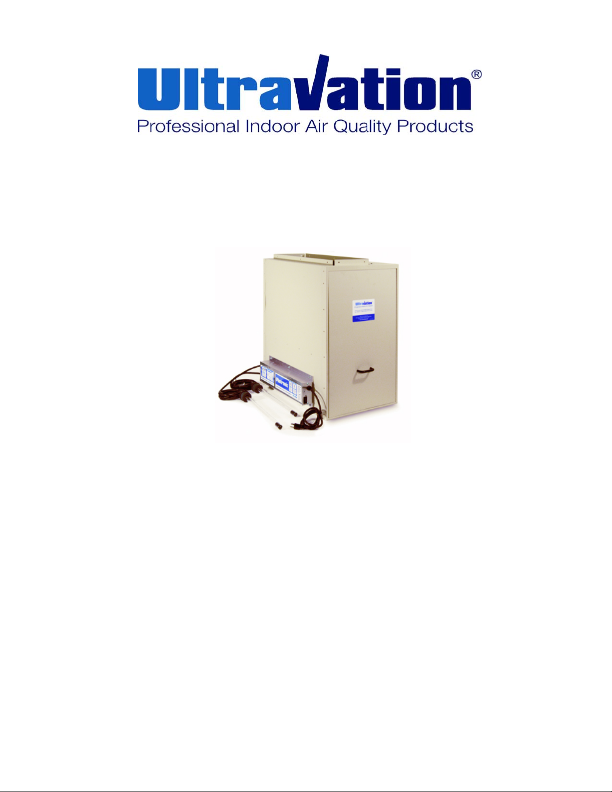
Photronic Complete Whole House Air Cleaning System
Right Angle Design (RAD)
OWNERS GUIDE
Models: 92-007, 92-008, 92-009 24VAC- 92-130, 92-131, 92-132
Table of Contents:
Page 2- Shipping and Packaging list, Introduction and Application, Safety Precautions, Power Consumption,
Page 3-Typical Mounting Positions, Installation of Electric Power Supply, Installation Requirements
Page 4- Germicidal Lamp Installation
Page 5- Maintenance, Replacing Filter
Page 6- Setting the Lamp Status Indicator, Replacing Photocatalytic Lamps, Replacing Germicidal Lamps
Page 7- Troubleshooting, Setting Indicator Light
Page 8- Applications with Humidifiers, Air Conditioners, Transitions
Page 9- Warranty, Replacement Part Numbers
LEAVE FOR HOMEOWNER
DC-IH-0203
Page 2
Shipping and Packaging List:
• Filter Housing including 2 Access Doors
• Merv 11 Media Air Filter
• PCO Filter
• Electrical Enclosure
• 1- Door Handle
• 1- UVA Lamp
• 4- ¾ inch 5/16 self tapping sheet metal screws
• *2- UVC Lamps Part:
12” UVC lamp option
OR
17” UVC lamp option
• *4- 1 inch UVC lamp mounting screws
• *8- 1/2 inch 5/16 self tapping screws
• *2- UVC Lamp Mounting Plates
• **100VA 24v secondary transformer
* Included when UVC option is purchased
** Includes 24v unit in purchase
Introduction and Applications:
This Ultravation Photronic Right Angle Design Air
Cleaner is a complete whole house air cleaning system.
This high efficiency air filtration unit is designed to
remove dirt, dust, pollen, and microscopic particles:
reduce unpleasant odors, VOC gases and the microbial
population from the air that circulates through it. By
adding this device to your HVAC system, you are
helping to create a cleaner indoor living environment for
your whole household.
The system works in 2-3 steps (depending on model
purchased, some models do not include the germicidal
protection in step 3)
STEP 1: Trapping particles in the pleats of the MERV 11
media filter. With an extra large surface area, the filter
allows for maximum dirt holding capacity and a long,
useful filter life with minimum air flow restriction.
STEP 2: VOC’s and gases such as the f umes from new
carpets, paints, nail polish, cigar and cigarette smoke
are drastically reduced photo chemically via a patented
process known as photocatalytic conversion or
photocatalytic oxidation.
(Option)STEP 3: Germicidal UVC light is applied to the
Air to drastically reduce or eliminate unwanted virus,
bacteria and mold.
This air cleaner is to be installed in a forced air heating,
cooling and ventilation system. It should be installed so
that all the system’s air is circulated through the filter first
and VOC Section second. The air cleaner will only filter
the air that is circulated through it. For maximum filtration
effect, set your blower to operate continuously. (Lower
speeds allow for higher efficiency)
Safety Precautions:
It is recommended that this unit be installed and
maintained by a trained technician:
WARNING: UV Hazard. Always protect eyes from
ultraviolet light. NEVER look at UV lamps in
operation. Unplug or disconnect power before relamping or servicing.
WARNING: Severe eye damage or temporary
blinding may occur.
WARNING: DO NOT operate outside of Air Handler.
Mount lamp base to duct first.
WARNING: No openings in duct are allowed which
would give direct line-of-sight to the UV light.
In the event of accidental breakage or replacement of
the ultraviolet lamp, please ensure that the lamp is
disposed of in accordance with local and state
environmental laws regarding fluorescent lamps
containing mercury.
Notice:
All wiring inside of the duct or air handling system in
direct line of site of the UV lamp must be shielded with
aluminum foil tape or equivalent non-combustible
material. When installing this unit, select a mounting
location that prevents ultraviolet light exposure to
plastic flexible duct liner or other plastic components
with unknown resistance to ultraviolet light. Ultraviolet
light may cause color shift or structural degradation of
plastic HVAC components
Power Consumption UV-A, UV-C lamps
Lamp Type Quantity Required
16-inch UV-A lamp is 36 watts 1
12-inch UVC lamp are 12 watts 2
17-inch UVC lamp are 22 watts 2
Note: Handle fits either door. A Phillips screw driver
will be required to install the handle. Handle holes are
behind the label on either door, depending on the
orientation of the installation.
2
Page 3
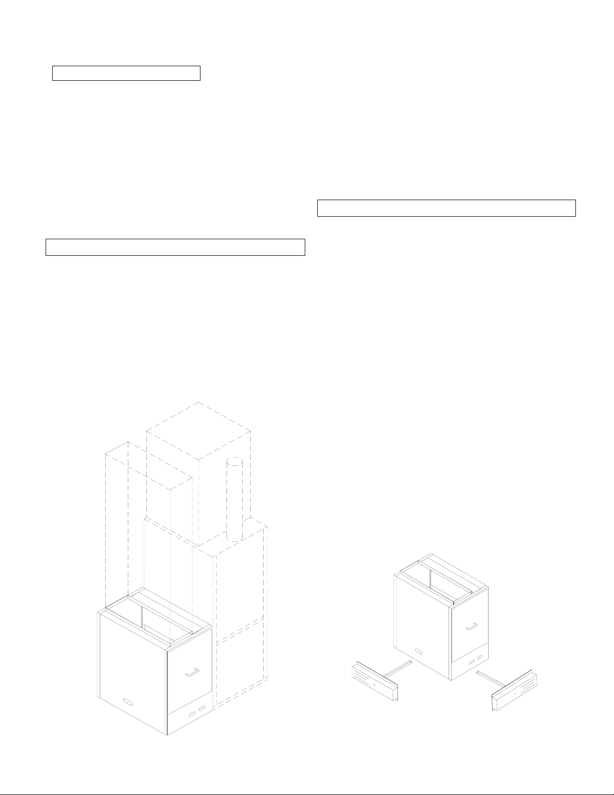
Installation requirements:
This unit is designed to be powered up constantly
and should not cycle on and off with a blower motor.
Unit must be installed either; within 6 feet of a 120 power
outlet, or hardwired per local and state electrical code
(Range 120-240VAC).
There must be at least 16 inches above the unit for
UVA lamp replacement.
There must be minimum 26 inches in front of the door for
filter replacement.
Installation – Filter Housing Cabinet
Ultravation RAD Photronic Air Cleaning Systems is
designed to be installed adjacent to the air handler.
The air cleaner is also designed to be internally
reversible with the airflow direction. They must be
installed in an area of the duct that precedes the blower
compartment. In this location, the blower motor and
internal components will be kept clean. This increases
air handler component life, improves system efficiency,
and reduces maintenance costs.
The Ultravation Right Angle Design Air Cleaner has
been designed for use in conjunction with virtually any
HVAC system.
Do not install this unit in the supply duct.
Be sure to plan adequate space for filter replacement.
Before installation is complete, seal all joints and
seams with duct tape or caulking.
Installation of Electronic Power Supply:
1. Determine the desired airflow path for installation
and determine available room for lamp replacement.
(This will determine the placement of the electrical
enclosure on the units – remove the knockout from the
filter cabinet)
2. Remove the cover from the electrical box.
3. Line up the lamp hole in the electrical enclosure with
the knockout on the filter cabinet and screw electrical
housing into place with provided hardware.
4. Install the twin tube (white in color) photocatalytic
lamp. When installed it is parallel to the Mesh filter.
5. The photocatalytic lamp clips into the socket with
diagonal pressure then seat back into place. (See
Illustration on page 6)
6. See instructions on setting the indicator light on
models utilizing UVC lamps. (page 6).
7. Reinstall the electrical cover.
* When the 24VAC power supply unit is purchased it
comes with a 100VA 24VAC secondary transformer to
be dedicated to the Ultravation equipment.
Electronics can be located
on either side or the back
(recommended)
depending on access for
3
Page 4

UV-C Germicidal Lamp, Stage 3, Installation
steps for Models with UVC option.
UV-C Germicidal Stage 3 is designed for installation in
the HVAC (heating, ventilation, and air conditioning)
system.
The optimum installation location for UV-C Germicidal
Stage 3 lamp is in the supply side ductwork exiting the
HVAC system before the ductwork branches.
The UV power supply should already be installed in the
previous step; the UVC lamps should be centrally located
within the air handler and positioned to achieve maximum
reduction of airborne pathogens.
Installation steps:
1. Determine a suitable location to install the UV-C
Lamps.
2. Select a location for the remote
assembly. Drill a 1” diameter hole for each lamp
assembly. Attach lamp module assembly with 2 screws
at the chosen location, or an optional lamp mounting
plate, which has been supplied to mount the lamp
assembly.
Note: The T3 UV lamp assembly can be removed
independently, simply by removing the 2 screws in
the lamp base.
3. Plug the rubber lamp connector fully onto the
installed UV lamp assembly. Be sure the 4 pinholes are
orientated properly to the 4 mating pins of the lamp.
Note: the pins are in a rectangular patent and can
only be mated in 2 positions. Pulling the lamp boot
back will help with the visual alignment of the pins
and connections. After making the connection be
sure to Push lamp boot over lamp base.
See the illustration of the T3 lamp 4-pin connector.
UV lamp module
Note:
This Photronic System and the UV-C lamps are
designed to operate constantly and should not cycle
on and off with a blower motor. Installation in a
return air duct is acceptable but not recommended in
a high dust environment.
Do not allow the UVC light to shine on the MERV 11
filter. The UVC energy will decompose the filter
within 120 days.
It is recommended a trained technician install this
unit. Never look at the UV lights without proper eye
protection.
4
Page 5

Maintenance:
The pleated filter media in your air cleaner must be
changed periodically. The frequency of filter
replacement is best determined by visual examination.
However, a bi-annual replacement of the 5” filter is
strongly recommended. Replacement filters may be
obtained through your installing contractor or local
dealer. - Actual replacement may vary depending on
the severity of dust and dirt particles.
If the Photocatalytic aluminum filter should become
dirty, it may be cleaned with low velocity
compressed air or vacuum only, no solvents or
water should be used. If the Photocatalytic section
becomes wet, allow the section to air dry before
reinstallation.
The aluminum mesh screen on the Photocatalytic filter
is coated using a patented process known to photo
chemically breakdown VOC’s and Odors as well as
reduce airborne pathogens on contact. Under normal
operating conditions this filter should last up to 10
years.
.
The Air cleaner should never be run with less than a
MERV-11* Filter.
Using less than a MERV-11* Filter rating will reduce
the effectiveness of this product. It is recommended
that this product be serviced and maintained by an
HVAC professional.
*MERV or Minimum efficiency rating value is a number
assigned to filters indicating their ability to capture
particles and dust, the higher the number the better the
filter. A MERV 11 filter is 40% more effective than a
MERV-8. Be sure that an Ultravation MERV-11 filter is
requested for replacements in this product.
Steps for replacing filters:
Pleated Media Filter:
1. Open the access door by Turning knob until
catch releases and then pulling toward you and
lifting up removing door completely.
2. Remove pleated filter and discard.
3. Slide new filter into cabinet with “airflow label
pointing in the direction of the airflow. Be sure
to seat new filter into top and bottom guide rails
to assure a good seal.
4. Replace access door.
Note: a gasket is provided to seal between the opening
on the side of the filtration cabinet and the side of the
air handler.
Aluminum PCO Filter:
1. Open the access door by lifting up then pulling
toward you to remove door completely.
2. Remove aluminum filter and discard
3. Slide new Aluminum PCO filter into cabinet
after media air filter in direction of airflow. Be
sure to seat the new filter into both top and
bottom guide rails to assure a good seal.
4. Replace access door.
5
Page 6

Lamp Status Indicator Light(s):
W
UVA Lamp:
There is a round knockout in the filter door that needs
to be knocked out and the included round viewport
needs to be inserted into the hole.
When the unit is on, if light is detectable through the
viewport then the UVA lamp is working.
UVC Lamps:
The Photocatalytic lamps and the UV-C should be
replaced at 2 years of operation, or when indicated by
the service monitor, located on the Photronic cabinet.
Once the indicator is set it will begin counting 9000
hours (approx. 1 year) of operation. After 9000 hrs of
operation it will signal that it is time to reset the counter
back to 0 and begin counting the next 9000 hours.
NOTE: 24VAC Power supply units do not have lamp
monitoring, please skip to next step.
On startup of the equipment:
1. Depress square yellow RESET button (hold down
for 10 sec.) on circuit board, the LED should turn Green
while the button is depressed.
2. Release the square yellow RESET button.
3. You now have set the internal clock to zero insuring
an accurate measurement of lamp life operating hours.
NOTE: When replacing lamps repeat steps above
to set the clock back to 0 to begin counting the
operating hours of the new lamp.
Steps for replacing Photocatalytic lamp:
1. Turn the systems power off.
2 Remove the screw(s) holding the cover, from the
top of the electronics housing.
3. Remove the cover; withdraw the lamp and
connector assembly (assembly does not fully remove.)
4. The connector snaps off from the lamps by
applying upwards pressure on side where the wires
are located.
5. Reverse the process with a new lamp.
Install and
Remove Lamp
socket as shown
Lamp Socket
Steps for replacing UVC lamps
1. Turn the systems power off.
2. Locate the remote lamp assembly, and remove the
rubber boot.
3. Remove the 2 screws from the plastic lamp base.
4. Withdraw the UVC lamp assembly from the
mounting location.
5. Reverse the process with new lamps. (New lamps
should be cleaned with a damp cloth or with
rubbing alcohol to remove any fingerprints and
debris prior to installation.)
T3 LAMP CELL BASE
SELF TAPPING MOUNTING SCREWS
LAMP SOCKET
T3 UV LAMP
( 2 REQ'D. )
TAMPER RESISTANT MOUNTING SCRE
( 4 REQ'D. )
Be sure to recycle the used lamps in accordance with
your local codes for fluorescent lamps. If you are not
sure on how to recycle the lamps please call the
Ultravation customer service line at 866-468-8247.
6
Page 7

Troubleshooting:
Important information: It is a normal characteristic of
all UV lamps to blacken around the filaments (ends) of
the lamp. This does not signify the lamp is defective or
not emitting Ultraviolet light.
The only time a UV lamp is defective is if it will not
light. UV Lamps that illuminate
Warranty.
Check for any loose or disconnected wiring
Lamps are securely plugged into their sockets
Verify the unit has power (120-240 volts) and the
Power switch is in the ON position
The electronic circuit of a 3-lamp system only operates
when all 3 lamps are operating. Unless a lamp is out of
orientation; therefore, make sure the lamps are
plugged in properly.
Verify 5 amp fuse is not blown by performing a
continuity test of the fuse.
NOTE: 24VAC Power supply units do not have
lamp monitoring, please skip to next step.
will not qualify for
Verify what signal if any the UV Lamp Monitor LED is
emitting. (See below).
Verify if in fact the UV lamps are on or off. Do not
look at the UV light without proper eye
protection.
Note: A flashing red every 1 seconds and a beep
every 1 seconds does not necessarily mean the
lamps are defective or no longer emitting UV; it is
sensing the lamp(s) in the unit are not on. This could
be caused by other factors.
In this case a service technician should be contacted.
Please contact your local dealer or HVAC contractor
for replacement lamps.
There are NO user serviceable replacement parts
other than the lamps and fuse.
Refer servicing to qualified service personnel.
UV-C, Lamp Status Monitor (if equipped):
LED
Color
Green
Solid Red
Pulsing Red
(Every 5 seconds)
Flashing Red
(Every 1 second)
.
Audible
Alarm
No audible
No Audible
Beep every
60 Minutes
Beep every 1
second
Unit
Status
OK
Reset lamp service indicator or replace lamp within 30 days,
occurs at approx. 11 months of operation
Lamp has exceeded 1 year of operation reset or replace lamps
UV lamp(s) are not lit. See note above.
7
Page 8

Service Indicator Light:
NOTE: 24VAC Power supply units do not have lamp
monitoring, please skip to next step.
The Photronic Series incorporates an audible and
visual annual service reminder indicator. A lamp status
monitor on the cover provides a visual LED signal
(solid GREEN) when the unit is operating correctly.
Other situations are covered on the chart on page 7.
(See UV lamp monitor chart- see page 7)
To set the service indicator Light: It is
recommended that a certified technician perform
this operation.
1. To set or reset the annual service indicator the unit
must have power to it.
2. Remove the cover from the unit.
3. Press down and hold the square yellow RESET
button (hold down for 10 sec.) on circuit board (located
adjacent to the LED on the circuit board), the LED
should turn GREEN while the button is depressed.
4. Release the square yellow RESET button.
5. Replace the cover, and inspect operation. LED
should be Green.
UV Lamp replacement:
NOTE: When replacing lamps after 1 year or 2 years of
operation disconnect power to the unit first.
After the lamps are in place, complete steps 1-5 to set
the service indicator to 0.
For optimum 24/7 air stream disinfection it is
recommend the UV-C lamp is replaced on an
annual basis.
Application with a Humidifier:
The Media Air Cleaner is compatible with humidifiers.
Avoid applications where water mist will reach the pleated
media filter.
When an evaporative type humidifier is used, it may be
installed between the furnace warm air duct and the return
air duct without affecting the air cleaner.
Atomizing and spray type humidifiers should be installed
with at least 6 feet between the Air cleaner and humidifier.
Air Conditioning:
The air cleaner should be installed upstream of the cooling
coil. This will keep the coil clean and reduce air
conditioning coil maintenance. Improved cooling efficiency
is the result, which directly affects energy costs. A clean
coil will reduce utility costs.
Failure to replace media can cause damage to the cooling
system.
8
Page 9

Warranty:
Ultravation warrants this product against any defects in material or workmanship for a period of 10 years after date of
purchase, with the exception of the disposable media filter, the UV Lamps, the fuse, the ductwork and installation.
The UV lamps are warranted for a period of 1year.
This warranty does not include damage to the unit from accident, misuse or improper installation. If this product
should become defective during the warranty period, Ultravation will elect to repair or replace the product free of
charge. Ultravation will return repaired or replaced warranted products pre-paid, provided that the product was
delivered pre-paid.
Ultravation shall have no responsibilities for charges incurred by the customer for installation or removal of warranted
items. Liability is limited only to the replacement or repair of this product.
This warranty gives you specific legal rights, and you may also have other rights, which vary from state to state.
All returns must be accompanied by a return authorization number, which may be obtained by contacting Ultravation,
Inc.
Ultravation, Inc.~ P.O. Box 234 ~ 218 Jones Drive ~ Brandon, Vermont 05733
Phone: 802-247-0034 ~ Fax: 802-247-0033 ~ www.ultravation.com
Replacement Parts:
20” x 25” x 5” MERV 11 Filter p/n: 91-006
16” x 25” x 1/2” PCO Filter p/n: 91-031
Photo Catalytic UV-A Lamps p/n: LP-PP-0052
12” UV-C Lamps (if equipped) p/n: AS-IH-1001
17” UV-C Lamps (if equipped) p/n: AS-IH-1003
Fuse- 5 amp p/n: EL-PP-0044
(See Serial Number Label on bottom inside panel for unit replacement part numbers)
9
 Loading...