

Page 1

Power Fogger Industrial Line
and PFI w/ LSG
Operator’s Manual
www.ultratecfx.com
VER. 30.10.10
Page 2

Table of Contents
Introduction ................................................................................ 3
Microprocessor Control ............................................................3
Water Base Fog Technology ...................................................... 3
Warning ...................................................................................... 3
Important Safety Instructions: ................................................... 3
Safety Precautions ..................................................................... 3
PFI Technical Specications ....................................................... 4
PFI Technical Drawings .............................................................. 4
Power Fogger Industrial ............................................................ 4
Power Fogger Industrial 9D ....................................................... 5
LSG w/ PFI Technical Drawings ................................................. 6
LSG PFI System on a Cart .......................................................... 6
LSG PFI System in a Roadcase ................................................... 6
Operating Procedure ................................................................. 7
Operating Procedure w Air Option ............................................ 7
Operation Procedure
LSG MK II High Pressure w/ 20 & 50lbs Cylinders ...................... 8
Figure A ................................................................................... 9
Figure B .................................................................................. 10
Operation Procedure
LSG MK II Low Pressure w/ 350lbs Dewar Tank ....................... 11
Figure C ................................................................................. 12
Options ..................................................................................... 13
Optional Show Control Remote Operations .......................... 13
Show Control Remote LED Indicator ....................................... 13
Show Control Operation ......................................................... 14
Optional Timer/ Duration Remote Operations ...................... 14
Timer/ Duration Remote LED Indicator .................................... 14
DMX Operation ........................................................................ 15
Maintenance ............................................................................. 15
Exterior ................................................................................... 15
Heat Exchanger ...................................................................... 15
Recommended Fluid ................................................................ 15
Maintenance Fluid .................................................................. 15
Warranty ................................................................................... 16
Contact Information ................................................................ 16
Note: Please read entire manual before operating the Power Fogger Industrial
www.ultratecfx.com
2
Page 3

Introduction
The Power Fogger Industrial is a Microprocessor Controlled, Water Based Fog generating system.
Microprocessor Control
The PFI features dual microprocessor control. From temperature regulation to taper back ow control, all of the
functions are monitored and processed by the two on-board processors.
Water Base Fog Technology
Water Base Fog technology is achieved by pumping a glycol/water mixture through a heat exchanger. This will
vaporize the uid as it passes through the hot unit. The vaporization of the uid forces the hot mixture through
the output nozzle. When mixed with ambient air, it forms an opaque aerosol (fog). The fog is made up of tiny
droplets that form around small particles in the air. The suspended droplets refract the light, allowing the fog to
take on the color of the light illuminating it.
Warning
Important Safety Instructions:
1. Do not touch, place hands or expose skin within 20” (50 cm) of the discharge nozzle.
2. Do not remove the outer case.
3. Persons suffering from asthma or allergenic sensitivity may experience irritation, discomfort or allergic
symptoms when exposed to fog effects.
4. Ensure that this unit is grounded at all times. Failure to do so may result in serious injury.
5. Use Ultratec Special Effects uid ON LY.
Safety Precautions
1. Ensure that any operation of the machine is supervised by suitably trained and authorized personnel.
2. Do not modify the machine or use a machine which has been damaged in any way.
3. Allow sufcient air circulation around the machine at all times.
4. Protect the machine from direct weather effects and wet locations.
5. Only use uids manufactured by Ultratec Special Effects.
6. Do not continue to produce fog when visibility is reduced to 20” 50cm or below.
7. Avoid directing fog output continuously at people, structures or objects within close proximity of the discharge
nozzle.
8. Ensure that adequate exhausting arrangements are available in the event of an emergency.
9. Do not place hands or exposed skin within the rst 20” (50 cm) of the discharge nozzle at any time during fog
production.
10. Fog effects can trigger smoke alarms and detectors. Please take suitable precautions to prevent false alarms.
11. Ensure sufcient air exchange vs. CO2 released.
www.ultratecfx.com
3
Page 4
PFI Technical Specications
Model: PFI/PFI-9D
Part Number: PFI
CLF 4450 / 120 volt
CLF 4451 / 220-240 volt
PFI-9D
CLF 4460 / 110 volt
CLF 4461 / 220-240 volt
Power Rating: 120 Volt A.C. 50/60 Hz. 13 Amps.
240 Volt A.C. 50/60 Hz. 6.5 Amps.
Fluid: Water Base Fog Fluid (Use only Ultratec Fluid)
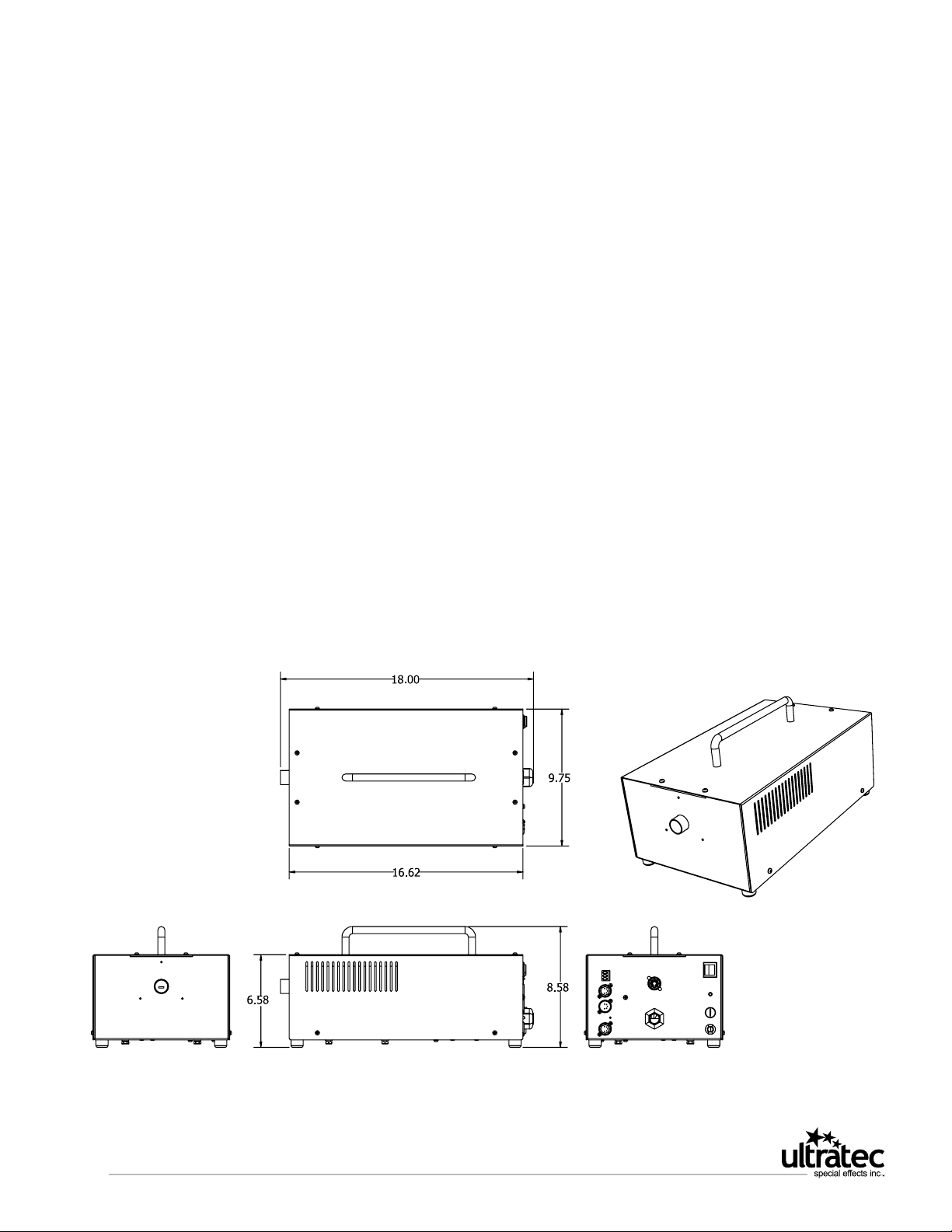
PFI Technical Drawings
Power Fogger Industrial
www.ultratecfx.com
4
Page 5
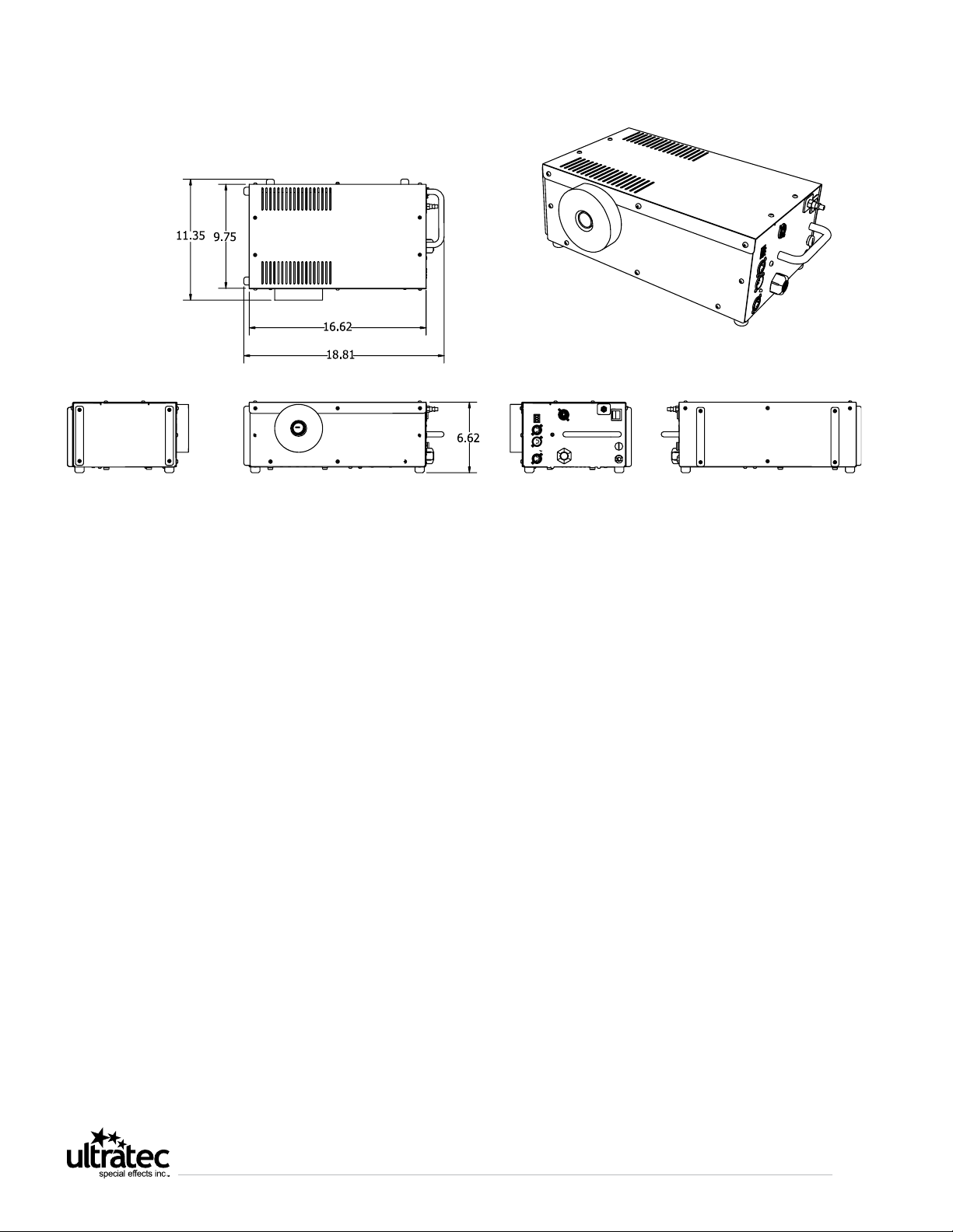
Power Fogger Industrial 9D
www.ultratecfx.com
5
Page 6

LSG w/ PFI Technical Drawings
LSG PFI System on a Cart
28.02
22
36
32.2
29.6
20
LSG PFI System in a Roadcase
39.5
24
23.25
28.75
34.5
www.ultratecfx.com
6
Page 7

Operating Procedure
1. The fog machine must be connected to a grounded supply of at least 15 amps free of any interference.
2. Open a 20 Litre (5 Gallon) container of Ultratec Special Effects fog uid and insert the uid pickup tube into the
spout of the uid container.
3. Connect the Remote Handset into the rear panel connector located on the rear panel. (When using DMX the
Remote is not required).
4. Activate the Power switch located on the rear panel. The Power switch and Handset indicator will illuminate to
indicate the presence of power. If the Handset indicator does not illuminate, ensure the connector is properly
inserted.
5. The Handset indicator will begin to ash slowly, but will speed up
when the fog machine is ready to operate. After approximately 9
minutes, the fog machine will be fully heated and is ready for full
output; the indicator will be on solid.
6. It may be necessary to prime uid into the system to expel any
air. The Variow control on the remote handset should be set to
the full position. A dry hose can take between 45-60 seconds to
prime. This only needs to be done if the unit was left to run dry.
7. To adjust the depth of the hose, simply loosen Nut ‘A’ and slide
up or down the hose and retighten. Be careful not to pinch off
the ow of uid.
NOTE: In order to prime the fog machine, the Handset Indicator must be a solid red.
Operating Procedure w/ Air Option
A) Mount the Regulator Bracket to a wall or other secure
location.
B) Attach the female coupler to the male coupler of the
Power Fog Industrial w/ Air Option or Power Fog Industrial
9D w/ Air Option.
C) Attach the air hose to the male coupler of the mounted
regulator.
D) Adjust for the desired air pressure (typically 25-50 psi).
C
A
A
D
A
B
A
www.ultratecfx.com
7
Page 8

Operation Procedure
LSG MK II High Pressure w/ 20 & 50lbs Cylinders
The Operation Procedures outlined in this section, refer to Figure A and Figure B on Page 9 and 10.
1. Place the fog machine’s output nozzle rmly against the center of the foam ring, sealing it to the input port of the
LSG MK II.
Tech Tip: Proper alignment can be observed by shining a ashlight into the 10” exit port of the LSG MK II and noting
the fogger’s output nozzle is centered on the LSG MK II input port.
2. Connect the blue Twist Lock connector from the LSG MK II into the controlling power source (i.e. control port on
the rear panel of the Power Fog Family of Ultratec Special Effects Foggers). This port can be controlled via DMX, the
Timer/ Duration Remote or the Show Control Remote.
Note: Starting the ow of CO2 before the fog allows the liquid CO2 to purge the gas CO2 from the lines. The Liquid
CO2 is required for correct operation. The rule of thumb formula for calculating the purge time is 1 second for every 3
feet of hose. As the unused liquid sits in the hose, it absorbs heat and converts to its gaseous state.
3. Use Molecular Fog Fluid and adjust the ow rate to the desired fog output level. Excessive fog ow will not cool
sufciently allowing the fog to rise off of the oor.
Warning: Always secure all cylinders to prevent tipping hazards.
4. An LSG MK II High Pressure requires high pressure CO2 cylinders. These are normally available in 20 & 50lb sizes. It
is recommended that cylinders equipped with liquid siphon tubes be used. If using 20lb cylinders without the siphon
tube, invert the bottles and place them in bottle racks.
Warning: We do not recommend inverting the 50 lbs cylinders. Use 50 lb cylinders equipped with liquid siphon tubes.
5. The CO2 supply hose is connected to the CO2 cylinder. Increased performance is available by connecting two or
more cylinders in parallel. Exercise safe handling and connection of the tank as indicated by the gas supplier. A
sealing washer is necessary to prevent leaks between the hose and valve and is available from your gas supplier.
6. Tighten the CO2 hose-tting snug with the appropriate wrench.
Warning: Wear eye protection and gloves to protect against cold and pressure hazards
7. Open valve(s) slowly counter-clockwise until ow can be heard. Verify the lines have no leaks before opening the
valve(s) fully.
8. When the fog machine is up to operating temperature, activate the control to start the CO2 for the desired purge
and pre-chill time. Purging of the CO2 gas can be noted by the change in the sound of ow. It is often desirable to
pre-chill the chamber and long runs of ductwork like a Fog Curtain. Now add fog to create the thick, white rolling
blanket that hugs the oor. On the Power Fog Family of Ultratec Special Effects Foggers, the CO2 is triggered by
DMX (DMX channel + 1) or by one of the remotes. To control using the remote, the DMX address is selected as 555.
This allows the Duration knob (turned up over 1/2 way) of the Timer/ Duration Remote or the second channel of the
Show Control Remote to trigger the LSG MK II.
www.ultratecfx.com
8
Page 9

9. Verify cool temperature output by using your hand and passing it through the fog-CO2 output noting the
temperature.
10. After use, turn off the valves and trigger the LSG MK II to depressurize the system before attempting to disconnect
hoses. Note that the valves and lines may be extremely cold during operation. Prevent handling and exing of lines
when chilled.
Figure A
Liquid Carbon Dioxide
LSG Control Signal
Fog Fluid
Installation Model Shown Above
Touring Model Available
High Pressure Bottles without Siphon
Tubes inverted to obtain liquid supply.
20 Litre Fluid
in a box
www.ultratecfx.com
9
Page 10

Figure B
Liquid Carbon Dioxide
LSG Control Signal
Fog Fluid
Liquid Siphon
Tube
Liquid Carbon
Dioxide
High Pressure Bottles w/
Liquid Siphon Tube
Installation Model Shown Above
Touring Model Available
www.ultratecfx.com
10
Page 11

Operation Procedure
LSG MK II Low Pressure w/ 350lbs Dewar Tank
The Operation Procedures outlined in this section, refer to Figure C on Page 12.
1. Place the fog machine’s output nozzle rmly against the center of the foam ring sealing it to the input port of the
LSG MK II.
Tech Tip: Proper alignment can be observed by shining a ashlight into the 10” exit port of the LSG MK II and noting
the fogger’s output nozzle is centered on the LSG MK II input port.
2. Connect the blue Twist lock connector from the LSG MK II into the controlling power source (i.e. control port on
the rear panel of the Power Fog Family of Ultratec Special Effects Foggers). This port can be controlled via DMX, the
Timer/ Duration Remote or the Show Control Remote.
Note: Starting the ow of CO2 before the fog allows the liquid CO2 to purge the gas CO2 from the lines. The Liquid
CO2 is required for correct operation. The rule of thumb formula for calculating the purge time is 1 second for every
three feet of hose. As the liquid sits in the hose unused it absorbs heat and converts to its gas state.
3. Use Molecular Fog Fluid and adjust the ow rate to desired fog output level. Excessive fog ow will not cool
sufciently allowing the fog to rise off of the oor.
4. An LSG MK II Low requires low pressure Liquid CO tanks. These are normally available in a 350lb size. These are
large vacuum tanks which keep the Liquid CO2 cold. Some CO2 is consumed during storage to maintain the liquid
at -56C. These tanks provide the best performance and price characteristics of the LSG systems. Check with your
local gas supplier for availability as not every location may carry these tanks.
Warning: Wear eye protection and gloves to protect against cold and pressure hazards.
5. You must connect the supply hose to the liquid output of the liquid CO2 tank. This is usually clearly indicated on
the Liquid CO2 Tank outputs. A sealing washer is necessary to prevent leaks and is available from your gas supplier.
6. Tighten the CO2 supply-tting snug with the appropriate wrench.
7. The tank pressure is indicated on the pressure gauge and must read between 275 - 340 psi to operate the LSG
MK II. This is achieved by opening the Pressure Builder Valve (by turning it counter clockwise) at least 1-3 hours in
advance.
8. Open the valve slowly counter-clockwise until ow can be heard. Verify the lines have no leaks before opening the
valve fully.
9. When the fog machine is up to operating temperature, activate the control to start the CO2 for the desired purge
and pre-chill time. Purging of the CO2 gas can be noted by the change in the ow sound. It is often desirable to
pre-chill the chamber and long runs of ductwork (i.e. Fog Curtain). Now add fog to create the thick, white rolling
blanket that hugs the oor. On the Power Fog Family of Ultratec Special Effects Foggers, the CO2 is triggered by
DMX (DMX channel + 1) or by one of the remotes. To control using the remote, the DMX address is selected as 555.
This allows the Duration knob (turned up over 1/2 way) of the Timer/ Duration Remote or the second channel of the
Show Control Remote to trigger the LSG MK II.
www.ultratecfx.com
11
Page 12

10. Verify cool temperature output by using your hand and passing it through the fog-CO2 output noting the
temperature.
11. After use, turn off the valves and trigger the LSG MK II to depressurize the system before attempting to disconnect
the hoses. Note that the valves and lines may be extremely cold during operation. Prevent handling and exing of
lines when chilled.
Figure C
Liquid Carbon Dioxide
LSG Control Signal
Fog Fluid
350lb Liquid Carbon
Dioxide Dewar
Installation Model Shown Above
Touring Model Available
www.ultratecfx.com
12
20 Litre Fluid
in a box
Page 13

Options
Remotes - The Show Control Remote and Timer/ Duration Remote are compatible with the Power Fog Industrial,
Power Fog Industrial w/ Air Option, Power Fog Industrial 9D and Power Fog Industrial 9D w/ Air Option. Each remote is
sold separately.
Jug Holder - The Power Fog Industrial 9D and Power Fog Industrial 9D w/ Air Option has
been designed to be versatile in any setting. For ease of operation, a jug holder may be used
to secure the uid to the machine. The Jug Holder is sold separately.
4” Hose Adapter - If your intention is to connect a 4” hose to the machine and direct the
fog elsewhere, a 4” Hose Adapter (CXP 1046) is available. This adapter is compatible with the
Power Fog Industrial, Power Fog Industrial w/ Air Option, Power Fog Industrial 9D and Power
Fog Industrial 9D w/ Air Option.
Optional Show Control Remote Operations
The Show Control Remote Handset was designed to indicate operation modes. These are as follows:
Show Control Remote LED Indicator
Slow Flashing Light: Indicates unit is not ready to operate but still in
heating mode, fog is not available at this point.
Quick Flashing Light: Indicates unit is ready to operate but still in
heating mode, some fog is available at this point.
Solid Light: Indicates that the unit is ready to fog at full output.
No Light: Indicates problems; a loss of power or remote is not connected.
If these fail to correct the problem, contact your local
Show Control
Input
Flow Control
Manual Fog
On/ Off Switch
www.ultratecfx.com
13
Page 14

Show Control Operation
Show control is achieved by connecting a “Dry” or zero voltage contact to the
show control terminals. The Power Fog Industrial requires no power to signal the
fog, only one set of contacts that close for the entire fogging cue.
For Show Control Operation, the DMX Address must be set on 555. Closing the
Show Control Remote terminals with dry contacts, triggers the following machine
functions:
C + 1 = On/ Off w/ Variow
C + 2 = LSG On
C + 3 = Air Option
Optional Timer/ Duration Remote
Operations
The Timer/ Duration Remote offers Duration, Interval, Variow and fog on/ off
controls.
Closed “Dry” Contact
Show Control
Timer/ Duration Remote LED Indicator
The Timer/ Duration Remote Handset was designed to
indicate operation modes. These are as follows:
Slow Flashing Light: Indicates unit is not ready to
operate but still in heating mode, fog is not available at
this point.
Quick Flashing Light: Indicates unit is ready to operate
but still in heating mode, some fog is available at this
point.
Solid Light: Indicates that the unit is ready to fog at full
output.
No Light: Indicates problems; a loss of power or remote is not connected. If these fail to correct the problem, contact
your local Ultratec Special Effects dealer.
Note: To operate the LSG MK II using the Timer/ Duration Remote, the DMX Address must be set on 555 and the
Duration control set over 50%. If the Duration is set at anything less than 50%, the Switched Power Port will be off.
The Interval Knob works in the same fashion for machines equipped with the Air Option. The Show Control Remote
and Timer/ Duration Remote cable may be extended from the machine and operated effectively away from the Power
Fog Industrial. The maximum recommended cable length is 225 Feet.
Manual Fog
On/ Off Switch
Duration
Variow
Interval
LED
www.ultratecfx.com
14
Page 15

DMX Operation
The Power Fog Industrial is equipped with DMX controls as a standard feature.
1. Attach a DMX signal to the DMX IN 5 pin connector on the rear of the unit. A terminator may be required on the
DMX OUT connector in some applications.
2. Select a valid DMX address on the thumbwheel selector for the base address of the fogger. If an air option is present
3 consecutive address will be required. Base DMX= fog rate controlled 0-100%, DMX+1=LSG power on above
50%, and DMX+2= air on above 50%.
3. Valid DMX LED is on solid if good DMX signal is present. DMX control overrides hand remotes. Slow or irregular
ashing indicates poor DMX data. A steady ashing indicates factory test mode and DMX switches were in the 600699 range at power-up. Reset switches to required address and cycle the main power switch.Recommended Fluids
Maintenance
Exterior
The casing of the PFI is stainless steel with a powder paint coating. To clean simply wash with mild soap and warm
water.
Heat Exchanger
Using high quality Ultratec Special Effects uid should result in a long heat exchanger life. (See warranty policy later in
this manual).
Recommended Fluid
Director’s Choice Fog Fluid: The choice of professionals. Director’s Choice creates a cloud of fog with a medium hang
time while remaining clean, white, dry, and odorless.
Pro Beam Long Lasting Fog Fluid: With a hang time 2-3x greater than the Director’s Choice Fog Fluid, the Pro Beam
solution produces a slightly less white fog while remaining clean, dry, and odorless.
Quick Dissipating Fog Fluid: This fast dissipating uid is great for applications or effects that require quick dissipation
of fog. It produces excellent steam effects that resemble nitrogen bursts and it also keeps low-lying fog from rising too
quickly when it is used with the LSG or LSX.
Extra Quick Dissipating Fog Fluid: Dissipates 2x the rate of Quick Dissipating Fog Fluid while maintaing similar
characteristics.
Molecular Fog Fluid: A faster dissipation versus the Director’s Choice Fog Fluid. This thick, clean, white fog is an
optimal solution for a dense low-lying fog effect when chilled with the LSG or LSX machines.
Party Fog Fluid: Quality fog uid on a budget. An excellent solution for Djs, Nightclubs, Haunted Houses etc., looking
to enhance light beams and creating various smoke effects.
Maxi Fog Fluid: The perfect balance between price and performance. Maxi Fog is the ideal solution for those who
require high volume without compromise.
Maintenance Fluid
EZ Kleen Preventative Maintenance Fluid: Using EZ Kleen preventative maintenance uid on a regular basis ensures
longer life for the heat exchanger in Ultratec fog machines by reducing blockage.
All of our Fog Fluids are water based. Damage will occur if Haze Fluid is used in the Power Fogger Industrial.
www.ultratecfx.com
15
Page 16

Warranty
Warranty: All warranty is for one year parts and labour unless specied or manufacturer defect only.
Abuse or Poor Maintenance will not be covered under warranty. Ultratec Special Effects Fluids
must always be used. Use of any non Ultratec Special Effects Fluids will void all warranties.
Accept no substitutions as there are no exceptions to this rule. Proof of Purchase or Proof of
Sale must always accompany any warranty returns. An RA (return authorization) number must
be noted on the outside of the box being returned to our facilities. Any packages without
a clearly marked RA number will not be accepted by our receiving department. Freight on
warranty items are freight prepaid to our facility and we will prepay freight back to your facility
after repair by the most economical means available. Should you require the item expressreturned, then you are responsible for any difference in freight cost.
Return Policy: Return of any product must be done within 30 days of purchase. The package must be
returned freight prepaid and the RA number clearly marked on the outside of the box.
Minimum restocking fee is 25%. Once our facility has received the product a technical
assessment will be completed to determine if an additional restocking fee needs to be issued.
Only credits are issued to the dealers account. Any product not returned within 30 days is
considered purchased.
Warning: Ultratec Special Effects Inc. considers all of it’s product to be safe for use in the application it
was intended. Ultratec Special Effects takes no responsibility for misuse or incorrect use. Always
refer to the Product Manual for proper use.
Contact Information
Head Ofce
Ultratec Special Effects Inc.
1960 Blue Heron Drive
London, Ontario N6H 5L9
Direct: 519-659-7972
Toll Free: 866-534-5557
Fax: 519-659-7713
Canadian Shipping Address
(For All Canadian Repairs)
Ultratec Special Effects Inc.
1960 Blue Heron Drive
London, Ontario N6H 5L9
Please remember to include the RA Number on all items being shipped for
repairs.
To get an RA Number, visit www.ultratecfx.com and click on the “Service” tab
and then click on “Master Service Tracker or contact service at 519-951-3357 /
866.534.5557
USA Shipping Address
(For All USA Repairs)
Ultratec Special Effects Inc.
640 Gadson St.
Groveland, Florida 34736
www.ultratecfx.com
16
 Loading...