

Page 1
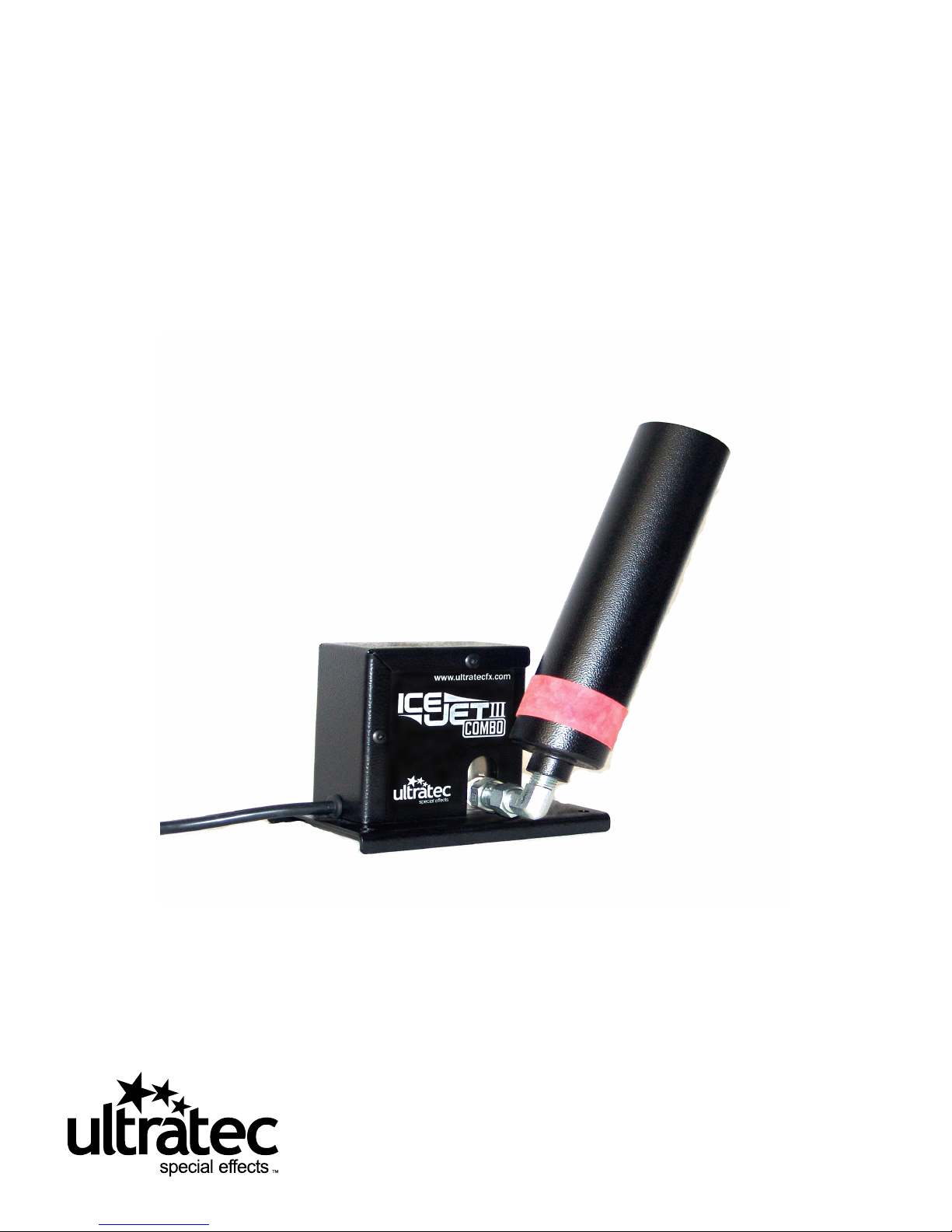
IceJet III
Operator’s Manual
www.ultratecfx.com
VER. 24.08.18
Page 2

Table of Contents
Warning ...................................................................................... 3
Safety Precautions ..................................................................... 3
Technical Specifications ............................................................. 4
Operating Procedure ................................................................. 5
CO2 Data .................................................................................... 6
Warranty .................................................................................... 7
Contact Information .................................................................. 7
Note: Please read entire manual before operating the IceJet III
www.ultratecfx.com
2
Page 3

Warning
Important Safety Instructions:
1. Do not remove the outer case.
2. Ensure that this unit is grounded at all times. Failure to do so may result in serious injury.
3. High pressure gas dangers.
Safety Precautions
1. Ensure that any operation of the machine is supervised by suitably trained and authorized personnel.
2. Do not modify or use an IceJet which has been damaged in any way.
3. Secure cylinders and Dewers from tipping.
4. Protect the machine from direct weather effects and wet locations.
5. Allow for safe venting of CO2 on Dewars.
6. Avoid directing output at people, structures or objects within close proximity of the discharge nozzle.
www.ultratecfx.com
3
Page 4

Technical Specications
Model:
Part Number:
Length:
Width:
Height:
Net Weight:
Power Rating:
Consumption:
Approvals:
IceJet III
CLF-2149 120 Volt 50/60 Hz.
CLF-2151 220-240 Volt 50/60 Hz.
6 in 15 cm
6.5 in 16.5 cm
10.4 in 26.5 cm
6 lbs 13 kg
20 Volt A.C. 50/60 Hz. 1 Amps.
1
240 Volt A.C. 50/60 Hz. 0.5 Amps.
0.4 lb/min. @ 350 psi to 1.1 lb/min. @ 1000
Q.P.S. certified to CSA standards, CE
Technical Drawings
www.ultratecfx.com
4
Page 5

Operating Procedure
1. Before operating the IceJet a site review is required. As the IceJet is capable if dispensing large quantities of Co2 in a room the
air exchange properties of the room must be determined. (See sample calculation below) Due to the nature of the Dewar tank
(low pressure system) some Co2 is consumed to keep the liquid Co2 cold. This Co2 is released around the tank. If early delivery is
required anticipate the loss of Co2 and the storage ventilation requirements. As both high and low IceJets require large tanks
have safe handling and transportation requirements prearranged.
2. The Ice jet must be connected to a grounded supply of at least 2/1 amps (110 v/220 v) free of electrical interference.
3 . While connecting the tank adapter check the sealing disk is clean and not worn. Inspect the burst disk for damage.
Inspect hoses for wear, blisters and cracks. While connecting fitting ensure they seat properly. Replace any component,
which is not in good repair.
4 . The IceJet produces thrust when operating. Place the IceJet on a flat surface and securely fasten it. Four mounting holes
are provided. An optional truss clamp may be used mounted to the ½” side hole. Position the nozzle to the desired direction
and tighten it in place.
5. Wear properly rated and fitting safety glasses and gloves. Hazards from pressure and freezing are present. On the lowpressure operation the tank pressure should be above 300 psi. Open the pressure builder 1 hour before ShowTime. Connect to
the liquid line on the tank. On a high-pressure cylinder use only dip tube equipped cylinders that allow liquid withdrawal. Slow
crack the tank valve watching and listening for leaks. If all is ok then open valves fully then close them back ½ turn.
6. The IceJet produces loud noise and high velocity flow during operation. Ensure the safety of persons and property around the
nozzle discharge. If controlling the IceJet from a lighting console place it on a non-dimming circuit to prevent damage. Apply the
correct voltage and the solenoid will open. You will note the sound change as the liquid Co2 makes its way to the valve. This
could take several seconds for long hose runs. The red band on the nozzle adjusts the amount of air drawn into the Co2 stream.
The size of the effect varies with the moisture concentration of the air. More moisture means more cloud formation.
7. The low-pressure IceJet will give better performance due to the chilled Co2 but the use of Dewars can be restrictive for some
applications. The high-pressure IceJet allows for smaller cylinders, which are easier to store, handle and acquire.
8. When finished with the IceJet turn off the tank valve (caution as it may be cold). Turn on the IceJet to allow the pressure to
escape. Leave the valve on several second extra to allow all the Co2 to flash off. Now disconnect the hose and tank adapter.
www.ultratecfx.com
5
Page 6

CO2 Data
1 pound = 8.741 (scf) gas
1 pound = 0.118 (gal) liquid
Specific gravity = 1.53 for gas
Air has 21% oxygen.
CO2 is heavier than air and will sink to lower areas and displace the air.
OSHA exposure 0.5% for 8 hours (TWA) or 3% for 15 minutes (STEL)
Things to watch for when using CO2 are the reduction of the oxygen content and the collecting of CO2 in low or confined
spaces. By planning the location and duration of the equipment safe operation can be implemented. CO2 monitors can be
installed in low or confined areas to alert personnel of the presence of a hazard. Portable monitors can be used to spot check
for the safe exposure levels. If the location is open and only needs an exposure limit this can be done by calculation. To calculate
the oxygen depletion you must know the size of the area and the amount of CO2 added. The user’s manual should give the
rate of CO2 the equipment consumes.
Sample Calculation
The IceJet can output 1 pound of CO2 per second of run time.
Our room size is 75’ long x 75’ wide x 18’ high = 101250 cubic feet. Approximately 100,000 cu ft.
If we run 3 IceJets for 25 seconds we add 75 pounds of CO2 to the room.
75 lbs. x 8.741 = 656 cu ft of CO2 added to the room.
If we take 100,000 – 656 we have 99344 cu ft of air left
Of this air we have 20,862 cu ft of oxygen (99344 x 21%)
Therefore we have 20,862/100,000 = 20.8% oxygen content left in the room.
This simple calculation leaves out several factors. All rooms have air exchange, which should be several times per
hour. Replacing the air to keep people comfortable requires more exchange than what’s accounted for by their
breathing. This will reduce the CO2 concentration significantly. The other major factor is the local concentration of
CO2 until it is dispersed into the room. This is the responsibility of the operator to ensure that exposure in this area
is safe.
Maintenance
The casing of the Ice Jet is stainless steel with a powder paint coating. To clean, simply wash with mild soap and
warm water. Keep hoses and ports covered to prevent dirt from entering, this can get into the valve and hinder
operation. Do not use teflon tape on connections as threads of teflon can detach and block the valve.
www.ultratecfx.com
6
Page 7
Warranty
Warranty: Hardware products come with a one year warranty on parts and labor. Unless stated otherwise,
this will refer to manufacturer defects only. All warranty is based on destination of the original
sale. Any additional costs incurred are the responsibility of the Dealer and/ or the customer.
Abuse or poor maintenance is not accepted. Proof of purchase or proof of sale must always
accompany all warranty returns. An RA (Return Authorization) number must be noted on
the outside of each box being returned to our facility. Any package(s) without an RA number
clearly marked, will not be accepted by our receiving department. Freight on warranty items are
freight prepaid to our facility and we will prepay freight back to your facility following repair.
This will be done by the most economical means available. Should you require the item expressreturned, the dealer is responsible for request indication and any difference in freight cost.
Export Distributors are required to carry out the warranty repair, parts will be supplied by
Ultratec.
Return Policy: Return of any product must be done within 30 days of purchase. The package must be
returned freight prepaid and the RA number clearly marked on the outside of the box.
Warning: Ultratec Special Effects considers all of it’s product to be safe for use in the application it was
intended. Ultratec Special Effects takes no responsibility for misuse or incorrect use. Always
refer to the Product Manual for proper use.
Contact Information
Head Ofce
Ultratec Special Effects
1960 Blue Heron Drive
London, Ontario N6H 5L9
Direct: 519-659-7972
Toll Free: 866-534-5557
Fax: 519-659-7713
Europe Ofce
Ultratec Special Effects GmbH
Dieselstrasse 30-40
60314
Frankfurt am Main
Germany
Direct: 49-69-87-000-1850
Fax: 49-69-87-000-1899
Canadian Shipping Address
(For All Canadian Repairs)
Ultratec Special Effects
1960 Blue Heron Drive
London, Ontario N6H 5L9
Please remember to include the RA Number on all items being
shipped for repairs.
To retrieve an RA number visit our website www.ultratecfx.com Enter
the "Fog and Atmosperic side". Select the "REQUEST RMA" tab along
the top of the screen. Enter the required information and select submit.
If you have any questions or require assistance please contact service at
519-951-3357/866-534-5557 or by email at Service@Ultratecfx.com.
USA Shipping Address
(For All USA Repairs)
Ultratec Special Effects
640 Gadson St, Unit 300
Groveland, Florida 34736
www.ultratecfx.com
7
 Loading...