

Ultra Start KEU-300 User Manual
INSTALL GUIDE
Covers All KEU-300 Series Advanced Factory
Keyless Upgrade Security Systems
www.ultrastarters.com
Technical Support: 866-698-5872 ext 0
support@ultrastarters.com
This device complies with Part 15 of the FCC rules. Operation is subject to the following conditions:
(1) This device may not cause harmful interference, and
(2) This device must accept any interference received, including interference that may cause
undesired operation.
CAUTION: Changes or modifications not expressly approved by the part responsible for compliance
void the user’s authority to operate this devise.
FCC/ID Notice
INSTALL MANUAL REMOTE VEHICLE SECURITY
PAGE 2
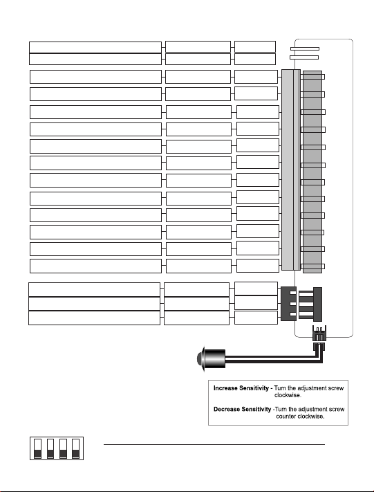
Starter Disable Relay
Starter Disable Relay
Ground When Armed
Ignition Input
Ground Input
12volt Constant Input
Horn/ Siren Input
Horn/ Siren Output
Flashing Park Light Output
Second Channel Output
Domelight/ Lock Output
Positive Door Input
Negative Door Input
Hood/ Trunk/ Sensor Input
Door Lock Wire Input
Door Unlock Wire Input
Unlock Switch Sense Input
Status LED/ Program Switch
Shock Sensor Sensitivity
See Page 5.
See Page 5.
See Page 3.
See Page 3.
See Page 3.
See Page 3.
See Page 4.
See Page 4.
See Page 3.
See Page 3.
See Page 3.
See Page 4.
See Page 4.
See Page 4.
See Page 4.
See Page 4.
See Page 4.
Brown
Brown
Orange
Yellow
Black
Red
Brown
Brown
White
Grey
Blk/Wht
Violet
Green
Blue
Green
Blue
Yellow
UP- ON
1 234
Down- OFF
Switch #1 Switch #2 Switch #3 Switch #4
Passive Chirp Delete Horn Mode Secure Valet
Active Chirp Enabled Siren Mode Valet Mode

REMOTE VEHICLE SECURITY INSTALL MANUAL PAGE 3
12 pin Main Harness
Red- +12volt Power Source Input.
Connect this wire to a +12 VDC constant power source. To Battery or Ignition
Harness.
Black- System Ground Input.
Connect this wire to chassis ground. To a clean unpainted metal surface.
Yellow- Switched ignition input.
Connect to switched ignition, 12VDC when the key is in the On, Start and
run positions. Found at Ignition Harness.
* If this input is connected to a wire that is not a true ignition wire the starter
disable and other functions may not work properly.
Grey- 250ma Second Channel Output. (Aux or Remote Start activation)
This wire will supply a 250ma output when the lock button on the transmitter
is pressed twice within 3 seconds.
*If the ignition turns on within 5 seconds, the Shock Sensor will be
automatically disabled until 10 seconds after the ignition shut back off.
Orange- 500ma Ground When Armed Output.
This wire can be used when adding accessories such as window roll-up
modules that require Ground when armed for activation.
White- 12volt Park Light Output
Connect this wire to the park light wire. Positive when the park light switch is
activated.
*Do not connect to the dimmer wire!
Black/White- 250ma Domelight or Door Lock Output.
This wire can be used as a 30 second output to activate the dome light or
be programmed for door lock output for Passive Door Lock Mode.
**250ma outputs are low current and are designed to activate relays**
Continued on next page...
 Loading...