


INSTALL GUIDE
U.S.A. Model
KE-5 Keyless Entry System
WWW.ULTRASTARTERS.COM
Technical Support 866-698-5872 ext 0
Support@ultrastarters.com
FCC/ID Notice
This device complies with Part 15 of the FCC rules. Operation is subject to the following conditions:
(1) This device may not cause harmful interference, and
(2) This device must accept any interference received, including interference that may cause
undesired operation.
CAUTION: Changes or modifications not expressly approved by the part responsible for compliance
void the user’s authority to operate this devise.

Installation Manual
KE-5
Table Of Contents....................................................................................... Page 2
System Contents.
Pre-Installation.
Installation Tips.
Main Wiring Diagram................................................................................... Page 3
Quick Start Installation................................................................................ Page 4
Wiring Description.
Transmitter Operation.
Transmitter Programming........................................................................... Page 5
System Reset
Quick View Programming Chart
System Programming................................................................................. Page 6
System Programming.................................................................................. Page 7
Relay Diagrams........................................................................................... Page 8
System Contents Key Features
- Control Module
- Four Button Remote
Transmitter(s)
- 10-Pin Harness
- Installation Guide
- Owners Manual
Pre-Installation
BEFORE STARTING:
- Discuss the optional features of the alarm with the owner of the vehicle.
- Do a walk around of the vehicle. (Note any scratches or dents)
- Check with the vehicle’s owner before installation of LED light.
- See if the owner has a preference for the location of the Valet Switch.
- Have vehicle wiring information ready before starting installation.
Installation Tips
- Leave a window open to avoid locking the key’s in the vehicle.
- Use seat covers and floor mats to protect the vehicle.
- Avoid disconnecting the battery.
- Unplug the dome light fuse to prevent battery drain.
- Test all connections with a voltmeter or circuit safe test light.
- Install the wire harness so that it is free of any moving parts.
- Solder all connections. Avoid using scotch-lok and crimp connectors.
- Pull the siren and optional hood pin wires through a factory rubber grommet
into the engine compartment.(Do not use the steering boot).
- Install the siren away from high heat sources and direct exposer to water.
- Keyless Entry With Drivers Door Priority
- Trunk Release Output
- Positive Park Light Output
- Panic Mode
- Horn Honk Output
- Starter Disable Output
KE-5
Installation Manual
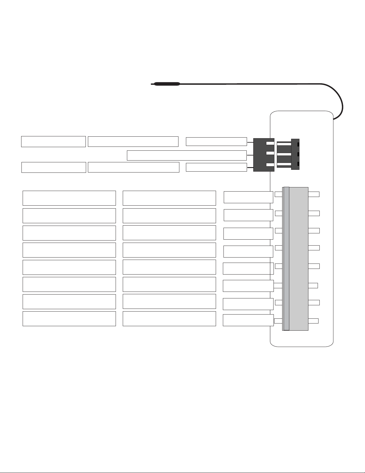
Antenna - Do Not Ground the antenna wire.
KE-5
(-)250ma Output
(-)250ma Output
Lock Output
Unlock Output
250ma Maximum Output
250ma Maximum Output
250ma Maximum Output
250ma Maximum Output
Switched Ignition Input
Constant 12 volt Input
Ground Input
Green
12volts For Door Lock Module Only
Blue
(-) Starter Kill Output
(-) Horn Honk Output
(-)Trunk Release Output
(-)Second Unlock Pulse
(+) Ignition Input
(+) Main Power Input
Chassis Ground Input
Orange
Brown
Gray
Pink
Yellow
Red
Black
10 Amp Output
*The 12volt output on the keyless entry connector is not to be used
for anything other than suppling power for voltage inverter’s, and door
lock modules such as the DL-3 and DL-7.
**250ma outputs are low current and are designed to activate relays.
(+) Park Light Output
White

KE-5
STEP 1 - The following wires MUST be connected for proper operation.
Re d 12vt Power (+) 15amp Input Constant 12vt power sourse.
Yellow Ignition (+) 12volt Input Main ignition wire.
White Park Lights (+) 15amp Output Connect to positive park lights
Black Ground (-) Input Connect to chassis ground.
Green Lock Output (-)500ma Output Connect to door lock relay.
Bl ue Unlock Output (-)500ma Output Connect to door unlock relay.
Optional Connections
Orange St.Disable (-)500ma Output Connect to Starter Disable relay.
Br o w n Horn Output (-)500ma Output Connect to horn relay.
Grey Trunk Output (-)500ma Output Connect to Trunk Release relay.
Pink 2nd Unlock (-)500ma Output Connect when installing Driver's Door Priority.
Installation Manual
STEP 2 - CONNECT AND MOUNT THE MODULE
Plug the Connectors into the Module. Press the transmitter buttons to check for
proper operation. Once it is determined that everything is working correctly the module
can be mounted.
***Before plugging the module in make sure that Ignition Key is in the OFF position***
Mount the module by selecting a location under the dash that is secure.
Be certain that the module does not obstruct any serviceable areas. The
module must be free from moving parts such as brake, clutch and gas
pedals and the linkages that are attached to them.
Basic remote operations
Lock
Unlock
Trunk
See Owners Manual for more transmitter
operations

KE-5
Installation Manual
TRANSMITTER PROGRAMMING
To add additional transmitters and delete existing transmitter code(s) from memory.
1) Turn the ignition On-Off-On-Off-On-Off-On-Off. The park lights will flash twice.
2) Press the Lock button on the transmitters to be programmed.
3) The park lights will flash once, each time a new transmitter is learned.
*** If this does not happen wait ten seconds and repeat steps 1-3.
Note: Each system can store a maximum of three transmitter codes in memory.
Transmitter Program on “Power Up”
1) Plug in the module. (Leave the ignition in the Off position).
2) Press the lock button on each of the transmitters to be programmed.
3) The park lights will flash once each time a new transmitter code is learned.
Note: Previous transmitters that are not programmed at this time will deleted from memory.
SYSTEM RESET
Reset To Factory Default Settings.
1) Make sure ignition is in the OFF position.
2) Turn the ignition key ON - leaving key in the ON position.
3) Press the transmitter buttons as follows. Trunk-Lock-Unlock-Trunk.
4) The system will respond by flashing the park lights three times
KE-5
The system is now set to factory default settings.
QUICK VIEW PROGRAM MENU
Entering The Program Menu
1) Make sure ignition is in the OFF position.
2) Turn the ignition key ON - leaving key in the ON position.
3) Press the transmitter buttons in the appropriate sequence.
4) After ten seconds the system will automatically exit Program Mode.
To change a Programmable Feature press the transmitter buttons as follows.
*** Default settings are shown in bold lettering.
Pass ive / Active Arming Lock-Unlock-Lock-Unlock Passive Active
Pass ive / Active Locks Unlock-Trunk-Unlock-Trunk Passive Active
Ignition Aouto Door Locks Lock-Trunk-Lock-Trunk ON OFF
Door Lock Pulses Lock-Unlock-Trunk-Lock Three Second .75 Second
Double Pulse Unlock-Trunk-Unlock-Lock Double Pulse Single Pulse
Passive Warning Chirps Lock-Trunk-Unlock-Trunk ON OFF
Reset To Factory Defaults Trunk-Lock-Unlock-Trunk Three flashes Three Flashes

KE-5
Entering The Program Menu
1) Make sure ignition is in the OFF position.
2) Turn the ignition key ON - leaving key in the ON position.
3) Press the transmitter button in the appropriate sequence.
4) After ten seconds the system will automatically exit Program Mode.
Setting 1 - Passive/Active Mode (Factory Default Setting: Active Mode)
Passive mode means that the system will automatically arm thirty seconds after
The ignition key is turned off and the last door of the vehicle is closed.
Sometimes referred to as Automatic Arming.
Active mode means that the system will not arm until you manually turn it on by
pressing the lock button on your transmitter.
1. Turn the ignition on. Ignition on means normal driving position.
2. Within 10 seconds, press and release the transmitter buttons
Lock Unlock Lock Unlock in succession.
PASSIVE MODE is confirmed with one horn chirp sound and one light flash.
ACTIVE MODE is confirmed with two horn chirp sounds and two light flashes.
Setting 2 - Passive Lock Mode (Factory Default Setting: Active Lock Mode)
Installation Manual
Passive Lock Mode means that all doors will lock automatically when the system
arms in the passive mode.
Active Lock Mode means that doors will lock only with the lock button.
1 Turn the ignition on. Ignition on means normal driving position.
2 Within 10 seconds, press and release the transmitter buttons
Unlock Trunk Unlock Trunk in succession.
PASSIVE LOCK MODE is confirmed with one horn chirp sound and one parking
light flash.
ACTIVE LOCK MODE is confirmed with two horn chirp sounds and two parking
Light flashes.
CAUTION: If the automatic door lock feature is installed and the system is
Programmed to passive lock mode the doors will lock automatically when the
system arms. It is always advisable to remove the ignition key each time you exit
the vehicle.
Setting 3 - Ignition Auto Locks (Factory Default Setting: Locks Off)
Ignition Lock Mode means that all doors will lock automatically two (2)Seconds after
the ignition key is turned on and will unlock automatically when the ignition
key is turned off. This assumes that the keyless entry option has been installed
by your Dealer. Sometimes referred to as Ignition Lock.
1 Turn the ignition on. Ignition on means normal driving position.
2 Within 10 seconds, press and release the transmitter button
Lock Trunk Lock Trunk in succession.
DRIVE LOCK MODE ON is confirmed with one horn chirp sound and one parking light
flash.
DRIVE LOCK MODE OFF is confirmed with two horn chirp sounds and two parking
light flashes.

Installation Manual
Setting 4 - Long Door Lock Pulse (Factory Default Setting: Pulse Off)
Long Door Lock Pulse means that the system can accommodate the factory
central locking systems of import vehicles having vacuum door lock actuators that
require a three-second lock pulse.
1 Turn the ignition on. Ignition on means normal driving position.
2 Within 10 seconds, press and release the transmitter buttons
Lock Unlock Trunk Lock in succession.
LONG DOOR LOCK PULSE MODE is confirmed with one parking light flash.
SHORT DOOR LOCK PULSE MODE is confirmed with two parking light flashes.
Setting 5 - Dual Unlock Pulse (Factory Default Setting: Dual Unlock Mode Off)
Dual Unlock Pulse means that the system can accommodate the factory central locking
systems of import vehicles having dual unlock pulse to unlock the driver and passenger
doors.
1 Turn the ignition on. Ignition on means normal driving position.
2 Within 10 seconds, press and release the transmitter buttons
Unlock Trunk Unlock Lock in succession.
KE-5
DUAL PULSE ON is confirmed with one horn chirp sound and one parking light flash.
DUAL PULSE OFF is confirmed with two horn chirp sounds and two parking light flashes.
Setting 6 - Passive Warning Chirp (Factory Default Setting: Warning Chirp Off)
Passive Warning Chirp means that in passive mode (4.1) the system gives soft
Warming chirp sounds during thirty second arming period after each temporary disarm.
1Turn the ignition on. Ignition on means normal driving position.
2Within 10 seconds, press and release the transmitter button
Lock Trunk Unlock Trunk in succession.
CHIRP ON is confirmed with one horn chirp sound and one parking light flash.
CHIRP OFF is confirmed with two horn chirp sounds and two parking light flashes.
Setting 7 -Reset to Factory Default
To Reset all programmable features to factory default setting:
1 Turn the ignition on. Ignition on means normal driving position.
2 Within 10 seconds, press and release the transmitter button
Trunk Lock Unlock Trunk in succession.
Reset to factory default is confirmed with three horn chirp sounds and three park
Light flashes.

KE-5
Start
IG1
Installation Manual
POSITIVE TRUNK RELEASE
Trunk Release
Switch
Grey
86
NEGATIVE PARK LIGHTS
Parking
Light Switch
87
87
87a
Trunk Release Solenoid
+12V
85
30
Parking Lights
White
STARTER KILL
IG2
ACC
Off
IG1
Start
Orange
86
87
Cut
x
87a
30
86
85
87a
Ground
85
30
To Starter Motor
or Relay
 Loading...