

REV.2006.04
INSTALL GUIDE
www.ultrastarters.com
Technical Support: 866-698-5872 ext 0
support@ultrastarters.com
Warning
CARBON MONOXIDE MAY CAUSE SERIOUS INJURY, EVEN DEATH!
It is the sole responsibility of the user to place the system in Service Mode
when parking in an enclosed area ex: garage, partially enclosed area
ex: carport, or when the vehicle is being serviced.

Table of Contents Page 2
Feature List Page 3
Installer Notes
Wiring Diagrams Pages 4-5
Auto/Optional Tach Learn Page 6
System Reset Page 7
Transmitter Programming
Entering Program Mode Page 8
Quick View Programming Pages 9
Program Menu 1 Pages 10-11
Program Menu 2 Pages 12-13
Program Menu 3 Page 14
Program Menu 4 Page 15
Diagnostics Page 16
Table of Contents
INSTALL GUIDE PAGE 2

Installer Notes:
PAGE 3 INSTALL GUIDE
Feature List
- Auto Tach learning.
- Run Time: 4/15/45 minutes
- Door locks: .125s/.75s/3s / Double unlock / Ignition lock/unlock
- Horn output 5ms/10ms/50ms
- Timer or Cold Start (LT series) with 4 different start intervals
- Programmable Wait to Start or (+/-) diesel Glow plug input
- Ground While Running/Anti-grind protection/Starter kill
- System Override Protection/Service Mode (Valet)
- Park light and LED diagnostics
- Panic mode - Car Finder mode
- Engine Idle mode - Turbo Timer mode
- Over load proection
INSTALL GUIDE PAGE 4
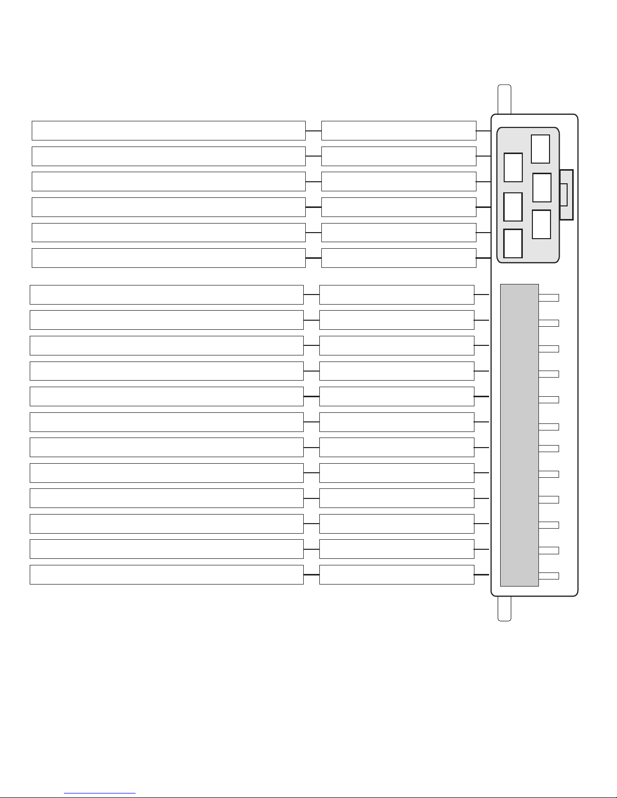
Wiring Diagram
11
55
33
22
44
66
1
2
3
4
5
6
7
8
9
10
11
12
YELLOW
YELLOW
WHITE/VIOLET
BLUE/WHITE
GREEN
RED/WHITE
WHITE
BLUE
RED
BROWN
GREEN/WHITE
RED
ORANGE
WHITE*
WHITE/BLUE
BLACK
BLUE
PINK
Re-arm Output (-)250ma
Ground While Running Output
Tach Detection Input (A/C)
Heater/Accessory Output (+)
Trunk Release Output (-)250ma
Park Light Output (+)10amp
Diesel Wait To Start Input (+or-)
12volt Input (+)30amp
Dis-arm Output (-)250ma
Hood Pin Switch Input (-)
Ignition Output (+)
Brake Switch Input (+)
Selectable Output (+)*
Horn Output (-)
System Ground Input (-)
12volt Input (+)30amp
Negative Park Light Output (-)250ma
Starter Output (+)
*Programmable Output (see program menu).
NOTE: 250ma outputs are low current and may require additional
parts (relays) to active optional features.
SEE OVERLOAD PROTECTION, PAGE 5
PAGE 5 INSTALL GUIDE
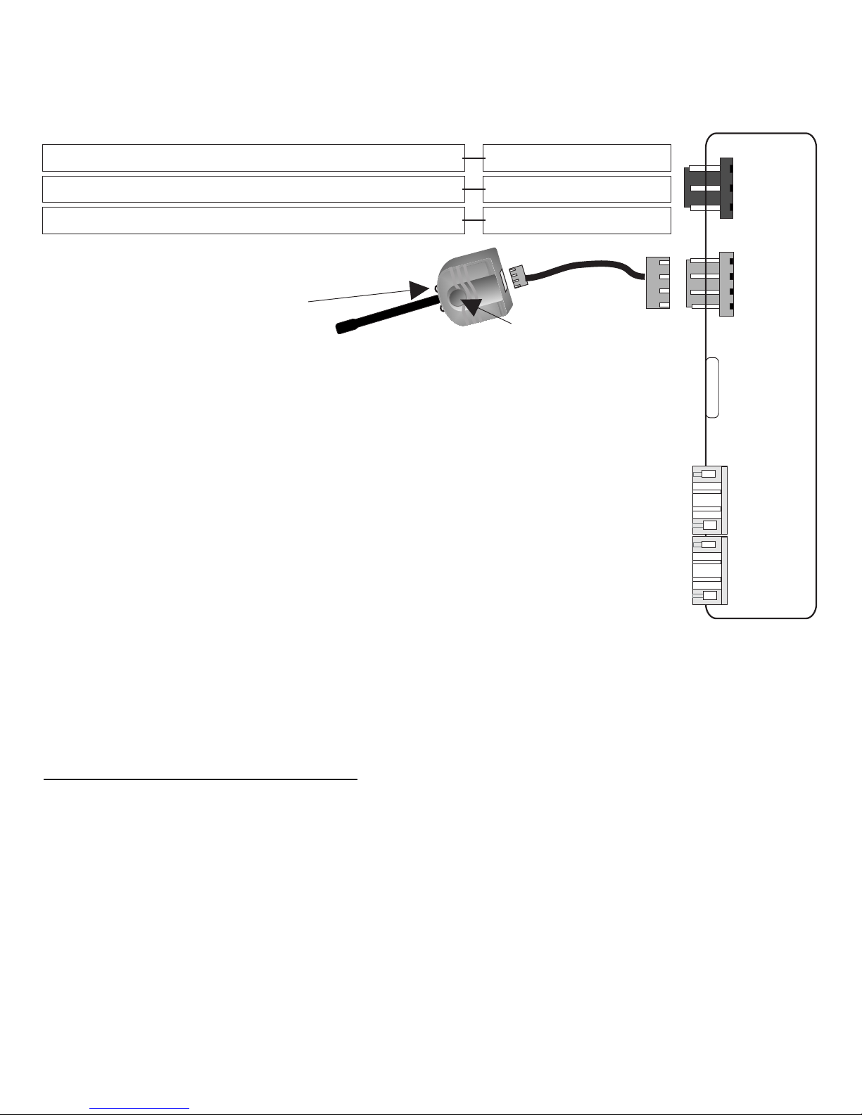
ACTIVE RF ANTENNA**
Status Led’s
Program Button
**The antenna MUST be connected for the system to operate
*The centre pin of the keyless entry harness is ONLY available with plug-in
devices such as the VP-1, DL-3, DL-7 and Data Bus Modules.
Overloading this output will damage the remote starter.
OVERLOAD PROTECTION:
All negative outputs are overload protected.
Example: Lock, Unlock, Dis-arm, Re-arm, etc...
If an output is overloaded the system will shutdown and flash the Park
Lights 9 times slowly.
** Future use.
1
2
3
1
2
3
4
Wiring Diagram
GREEN
RED*
BLUE
Door Lock Output (-)250ma
12volt Output (+)250ma (see notes above)*
Door Unlock Output (-)250ma
1
2
3
4
1
2
3
4
JP1
JP2
Bypass module**
Expansion module**

INSTALL GUIDE PAGE 6
IMPORTANT! The system must be Tach Learned before remote starting.
Auto Tach Learn:
Start the vehicle with the key. To confirm that a proper tach signal is
detected the system will flash the park lights and the horn (optional)
will honk three times.
Optional Tach Learn (vehicles without 12volt start output):
Press and Hold the brake pedal. Start the vehicle with the key then
press and release the program button 2-3 times within 2 seconds.
To confirm that a proper tach signal is detected the system will flash
the park lights and the horn (optional) will honk three times.
* If tach does not learn check for proper connection on the BLUE ignition
wire at the 6-pin connector. This wire should be connected to the vehicle
main ignition wire and must not turn off during the start position. If the
ignition connection is correct, reset the system (System Reset page 7).
New - If the original Tach source is changed a system reset must be
preformed before a new tach signal can be learned to the system.
For best results connect the tach wire to a fuel injector wire.
(See page 7 for System Reset).
NOTES: 1) If the vehicle does not start when the remote starter
is activated, the park lights will flash a diagnostic
code. (See Diagnostic Chart page 16).
2) If the vehicle still does not start, check all connections
and check for a factory installed Anti-Theft system.
Auto/Optional Tach Learn

PAGE 7 INSTALL GUIDE
A system reset will clear any changes made to the Program Menu’s
as well as the Tach setting. When the system reset is complete the
system must be Auto Tach learned before the remote starter will
operate.
1) Within 3 seconds turn the ignition key from “Off” to “On” 3 times,
ON-OFF-ON-OFF-ON. (Leave the key in the ON position)
2) Press and release the Program Button located on the antenna.
The park lights will turn on and the horn (optional) will honk one time.
3) Then press and hold the Program Button until the park lights flash
and the horn (optional) will honk 3 times to confirm system reset.
NOTE: System Reset does not delete the transmitter codes from
memory and does not default MENU 2, SETTING 1.
System Reset
Remote Transmitter Learn
STEP 1 - Within 3 seconds turn the ignition key to the “ON”
position three times leaving “ON” the third time.
NOTE:
STEP 3 - While holding the Program Button, press and release the
button on each of the remote transmitters to be programmed.
If the parking lights do not turn “ON”, release the Program Button and
turn the ignition to the “OFF” position, wait 5sec and repeat steps 1 & 2.
STEP 2 - Press and hold the Program Button. The park
lights will turn “ON” and the horn (optional) will
honk once. Continue to hold the Program
Button, the park lights will turn “OFF” and the
horn (optional) will honk 5 times quickly.
IMPORTANT! All remote transmitters not programmed at this time
will be erased from memory for security.

INSTALL GUIDE PAGE 8
STEP 1: With the ignition key in the “Off” position, within three seconds, turn
the ignition key to “On” position 3 times. ON-OFF-ON-OFF-ON
NOTE: Leave the key in the “On” position.
STEP 2: Press and release the program button. The park lights will flash and
the horn (optional) will honk to confirm entering program mode.
STEP 3: Select desired Program Menu See Quick view programming page 12.
The park lights will flash and horn (optional) will honk to confirm.
STEP 4: Select Programmable Setting:
a) Press and Release the Program Button the correct number of times to
select the desired Programmable Setting.
NOTE: The LEDs will flash and the horn (optional) will honk the number of times
for the appropriate Programmable Setting that has been selected.
For example: 1 flash/honk= Program Setting 1; 2 flashes/honks= Program
Setting 2; 3 flashes/honks= Setting 3; etc…
b) Press and Hold the Program Button until the park lights flash and the
horn (optional) honks the appropriate number of times of the chosen
Option in the Programmable Setting.
For example: 1 flash/honk= Option 1; 2 flashes/honks= Option 2; 3 flashes/
honks= Setting 3; etc...
NOTE: The Program Menu may be changed at any time by repeating STEP 2.
This will allow the installer to jump from one Menu, then quickly jump to
another Menu and change another Programmable Setting without
re-entering Program Mode.
To Exit: Turning the ignition key to the “Off” position or 30 seconds of no activity.
This will be confirmed with a light flash and a long horn (optional) honk.
Press and
Release the
Program Button
For Menu 3,
press the
button
For Menu 1,
press the
button
For Menu 4,
press the
button
For Menu 2,
press the
button
Entering Program Mode
Ignition 3x
On/Off
On/Off On

PAGE 9 INSTALL GUIDE
1 Flash 2 Flashes 3 Flashes 4 Flashes
Menu 1 - Lock Button
1. Ignition Lock Disabled Enabled Lock Only
2. Door Lock/Unlock Pulses 0.750 sec. Pulse 0.125 sec. Pulse 3 sec. Pulse Double Unlock
3. Disarm Pulse 0.750 sec. Pulse 0.125 sec. Pulse
4. Re-Lock Pulse Normal Before/ After/ Shutdown Shutdown Only
5. Horn Output All Enabled Lock/ Unlock Enabled Chirp 2nd Lock press No chirps
6. Horn Timing 10 ms (regular) 5 ms (quiet) 50 ms (loud)
Menu 2 -Unlock Button
1. Selectable Output Setting 2nd Ignition 2nd Starter 2nd Accessory
2. Rearm/ Aux 1 Rearm (-) Starter Output
3. Rearm Output All Lock/ After Start After Start
4. Trunk/ Aux 2 Trunk (max 5 sec) Defrost Pulse Aux 2 (no disarm/unlock) Car Finder
5. Disarm/ Aux 3 Disarm Dome light supervision
6. Neg. Park Light / GWR Neg. Park Light GWR/ Anti-grind
7. Parking Lights Normal 30 seconds with Unlock
8. Secure Valet Mode Hold for 10 secs. Hold for 15 secs.
Menu 3 - Star Button
1. Gas/ Diesel Mode Gas/ (+) 30 sec. (-)/ 30 seconds (-)/ 15 seconds
2. Run Time 15 Minutes 4 Minutes 45 Minutes
3. Crank Time 5 Seconds 10 Seconds 3 Seconds
Menu 4 - Number Button
1. Tach Setting Tach (tach connected) Tachless (tach not connected)
2. Tach Adjustment Decrease 5% Increase 5%
3. Over Crank None 0.250 seconds 0.500 seconds
4. Tach wait None 0.500 seconds 1.500 seconds
Quick View Programming
*See the following pages for more detailed programming instructions.

INSTALL GUIDE PAGE 10
Menu 1
Press and
Release the
button for
Menu 1
Press and Release
the Program Button
# of Times for
Setting Chosen
Press and Hold
the Program Button
to Change Option
Ignition 3x
On/Off
On/Off On
Press and
Release the
Program
Button
Setting 1 Ignition Auto Lock
1) Disable 1 Flash/Honk Lock/Unlock with remote transmitter ONLY.
2) Enable 2 Flashes/Honks Doors Lock/Unlock with Ignition key.
3) Ignition Lock Only 3 Flashes/Honks Doors Lock when ignition is turned “ON” only.
Press & Release the Program Button 1 Time (Setting 1) Confirmed with 1 LED flash.
Press & Hold the Program Button until the appropriate # of park lights/horn (optional) honks, then release
Press & Release the Program Button to proceed to the next step.
Setting 2 Door Lock Options
1) .750 Sec. Pulse 1 Flash/Honk .750 Second Lock/Unlock Pulses.
2) .125 Sec. Pulse 2 Flashes/Honks .125 Second Lock/Unlock Pulses
3) 3 Sec. Pulse 3 Flashes/Honks 3 Second Lock & Unlock Pulses.
4) Double Unlock Pulse 4 Flashes/Honks 1=.250 sec. & 1=.500 sec. Unlock pulse.
Press & Release the Program Button 2 Times (Setting 2) Confirmed with 2 LED flashes.
Press & Hold the Program Button until the appropriate # of park lights/horn (optional) honks, then release.
Press & Release the Program Button to proceed to the next step.
Setting 3 Disarm Pulse Duration
1) Normal Pulses 750ms pulses on Unlock & Disarm outputs.
2) Short Pulses 125ms pulses on Unlock & Disarm outputs.
Press & Release the Program Button 4 Times (Setting 4) Confirmed with 4 LED flashes.
Press & Hold the Program Button until the appropriate # of park lights/horn (optional) honks, then release.
Press & Release the Program Button to proceed to the next step.
continue page 16...
1 Flash/Honk
2 Flashes/Honks
Press & Release the Program Button 3 Times (Setting 3) Confirmed with 3 LED flashes.
Press & Hold the Program Button until the appropriate # of park lights/horn (optional) honks, then release.
Press & Release the Program Button to proceed to the next step
Setting 4 Rearm Output (12 pin auxiliary connector pin 8)
1) Type 1 1 Flash/Honk Pulse with Lock and after shutdown.
2) Type 2 2 Flashes/Honks Unlock before start. Lock pulse after start and shutdown.
3) Type 3 3 Flashes/Honks Pulse after start only.

PAGE 11 INSTALL GUIDE
Setting 5 Horn Honk Output (12 pin auxiliary connector pin 3)
1) All confirmation 1 Flash/Honk Horn honk confirmation on all functions.
2) Lock/ Unlock enabled 2 Flashes/Honks Horn honk confirmation on Lock/Unlock only
3) 2nd Lock press 3 Flashes/Honks Horn honk confirmation on 2nd Lock press..
4) No Honks 4 Flashes/Honks No honk confirmations.
Press & Release the Program Button 5 Times (Setting 5) confirmed 5 LED flashes.
Press & Hold the Program Button until the appropriate # of park light/horn (optional)honks, then release.
Press & Release the Program Button to proceed to the next step.
Setting 6 Horn Honk Timing (12 pin auxiliary connector pin 3)
1) 10 ms Pulse Output 1 Flash/Honk Normal (regular) Horn Output Pulses.
2) 5 ms Pulse Output 2 Flashes/Honks Short (quiet) Horn Output Pulses.
3) 50 ms Pulse Output 3 Flashes/Honks Long (loud) Horn Output Pulses.
Press & Release the Program Button 6 Times (Setting 6) confirmed 6 LED flashes.
Press & Hold the Program Button until the appropriate # of park light/horn (optional)honks, then release.
Press & Release the Program Button to proceed to the next step.
Menu 1 - continued...

INSTALL GUIDE PAGE 12
Menu 2
Press and
Release the
button for
Menu 2
Ignition 3x
On/Off
On/Off On
Press and
Release the
Program
Button
Press and Release
the Program Button
# of Times for
Setting Chosen
Press and Hold
the Program Button
to Change Option
Setting 1 Selectable Output (6 pin main connector pin 5)
1) Ignition 2 1 Flash/Honk 2nd Ignition Output
2) Starter 2 2 Flashes/Honks 2nd Starter Output
3) Accessory 2 3 Flashes/Honks 2nd Accessory Output
Press & Release the Program Button 1 Time (Setting 1) Confirmed with 1 LED flashes.
Press & Hold the Program Button until the appropriate # of park lights/horn (optional) honks, then release.
Press & Release the Program Button to proceed to the next step.
Setting 2 Re-arm/ Aux output (12 pin auxiliary connector pin 8)
1) Re-arm 1 Flash/Honk (-) 250ma Re-arm output.
2) Starter 2 Flashes/Honks (-) 250ma Starter output.
Press & Release the Program Button 2 Times (Setting 2) Confirmed with 2 LED flashes.
Press & Hold the Program Button until the appropriate # of park lights/horn (optional) honks, then release.
Press & Release the Program Button to proceed to the next step.
Setting 3 Re-arm Output (12 pin auxiliary connector pin 8)
1) Type 1 1 Flash/Honk Re-arm pulse after start/ shutdown and with Lock.
2) Type 2 2 Flashes/Honks Re-arm pulse after start and with lock.
3) Type 3 3 Flashes/Honks Re-arm pulse after start only.
Press & Release the Program Button 3 Times (Setting 3) Confirmed with 3 LED flashes.
Press & Hold the Program Button until the appropriate # of park lights/horn (optional) honks, then release.
Press & Release the Program Button to proceed to the next step.
Press & Release the Program Button 4 Times (Setting 4) Confirmed with 4 LED flashes.
Press & Hold the Program Button until the appropriate # of park lights/horn (optional) honks, then release.
Press & Release the Program Button to proceed to the next step.
Setting 5 Disarm/ Aux. 3 (12 pin auxiliary connector pin 10)
1) Disarm Output 1 Flash/Honk (-) 250ma output before remote start/ unlock.
2) Dome light Supervision 2 Flashes/Honks (-) 250ma output with unlock button (30 sec.).
Press & Release the Program Button 5 Times (Setting 5) Confirmed with 5 LED flashes.
Press & Hold the Program Button until the appropriate # of park lights/horn (optional) honks, then release.
Press & Release the Program Button to proceed to the next step.
continue page 18...
Setting 4 Trunk/ Aux. 2 (12 pin auxiliary connector pin 9) HOLD #.
1) Trunk Output 1 Flash/Honk (-) 250ma output when # held 5 sec.
2) Defrost Output 2 Flashes/Honks (-) 250ma pulse output after start.
3) Auxiliary 1 Output 3 Flashes/Honks (-) 250ma output with no disarm/unlock.
4) Car Finder 4 Flashes/Honks (-) 250ma pulsed horn output when # held 5 sec.

PAGE 13 INSTALL GUIDE
Setting 6 Negative Park Light/ GWR (12 pin auxiliary connector pin 11)
1) Negative Park Light Output 1 Flash/Honk (-) 250ma output with lock.
2) GWR/ Anti-Grind Output 2 Flashes/Honks (-) 250ma output while remote starter active.
Press & Release the Program Button 6 Times (Setting 6) Confirmed with 6 LED flashes.
Press & Hold the Program Button until the appropriate # of park lights/horn (optional) honks, then release.
Press & Release the Program Button to proceed to the next step.
Setting 7 Parking Light Output (12 pin auxiliary connector pins 5)
1) Park Lights 1 Flash/Honk Normal Park Light Flashes
2) 30 sec. Output 2 Flashes/Honks Park Light output active 30 seconds with UNLOCK.
Press & Release the Program Button 7 Times (Setting 7) confirmed 7 LED flashes.
Press & Hold the Program Button until the appropriate # of park light/horn (optional)honks, then release.
Press & Release the Program Button to proceed to the next step.
Setting 8 Secure Valet Mode (time required to set the system into Service Mode)
1) Normal Valet 1 Flash/Honk Hold the Program Button for 10 seconds
2) Secure Valet 2 Flashes/Honks Hold the Program Button for 15 seconds
Press & Release the Program Button 8 Times (Setting 8) confirmed 8 LED flashes.
Press & Hold the Program Button until the appropriate # of park light/horn (optional)honks, then release.
Press & Release the Program Button to proceed to the next step.
Menu 2 - continued...

INSTALL GUIDE PAGE 14
Menu 3
Press and
Release the
button for
Menu 3
Ignition 3x
On/Off
On/Off On
Press and
Release the
Program
Button
Press and Release
the Program Button
Number of Times for
Setting Chosen
Press and Hold
the Program Button
to Change Option
Setting 1 Gas/ Diesel Modes (12 pin auxiliary connector pin 1)
1) Gas/ (+)Input 1 Flash/Honk 2 sec Gas mode, (+) Glow plug input (max 30sec.).
2) (-) Input 2 Flashes/Honks (-) Glow plug input (max 30 sec.)
3) Time Delay 3 Flashes/Honks 15 second delay before remote start.
Press & Release the Program Button 1 Time (Setting 1) Confirmed with 1 LED flashes.
Press & Hold the Program Button until the appropriate # of park lights/horn (optional) honks, then release.
Press & Release the Program Button to proceed to the next step.
Setting 2 Run Time
1) 15 Minutes 1 Flash/Honk Runs for approx. 15 minutes when activated.
2) 4 Minutes 2 Flashes/Honks Runs for approx. 4 minutes when activated.
2) 45 Minutes 3 Flashes/Honks Runs for approx. 45 minutes when activated.
Press & Release the Program Button 2 Times (Setting 2) Confirmed with 2 LED flashes.
Press & Hold the Program Button until the appropriate # of park lights/horn (optional) honks, then release.
Press & Release the Program Button to proceed to the next step.
Setting 3 Maximum Crank Time
1) 5 Seconds 1 Flash/Honk 5 sec max time that the starter will stay engaged.
2) 10 Seconds 2 Flashes/Honks 10 sec max time that the starter will stay engaged.
3) 3 Seconds 3 Flashes/Honks 3 sec max time that the starter will stay engaged.
Press & Release the Program Button 3 Times (Setting 3) Confirmed with 3 LED flashes.
Press & Hold the Program Button until the appropriate # of park lights/horn (optional) honks, then release.
Press & Release the Program Button to proceed to the next step.

PAGE 15 INSTALL GUIDE
Setting 1* Tach/ Tachless (12 pin auxiliary connector pin 7).
1) Tach 1 Flash/Honk Blue/White pin 7 Must be connected.
2) Tach-less 2 Flashes/Honks No connection Blue/White pin 7.
Press & Release the Program Button 1 Time (Setting 1) Confirmed with 1 LED flashes.
Press & Hold the Program Button until the appropriate # of park lights/horn (optional) honks, then release.
Press & Release the Program Button to proceed to the next step.
Setting 2 Tach Adjustment.
1) Decrease 1 Flash/Honk Decrease Start output by 5%
2) Increase 2 Flashes/Honks Increase Start Output by 5%
Press & Release the Program Button 2 Times (Setting 2) Confirmed with 2 LED flashes.
Press & Hold the Program Button until the appropriate # of park lights/horn (optional) honks, then release.
Press & Release the Program Button to proceed to the next step.
Setting 3 Over-Crank Adjustment.
1) None 1 Flash/Honk No over-crank adjustment.
2) .250 adjustment 2 Flashes/Honks 250ms over-crank adjustment.
3) .500 adjustment 3 Flashes/Honks 500ms over-crank adjustment.
Press & Release the Program Button 3 Time (Setting 3) Confirmed with 3 LED flashes.
Press & Hold the Program Button until the appropriate # of park lights/horn (optional) honks, then release.
Press & Release the Program Button to proceed to the next step.
Setting 4 Tach Wait.
1) None 1 Flash/Honk No Tach wait.
2) 500 seconds 2 Flashes/Honks 500ms Tach wait..
3) 1.5 seconds 3 Flashes/Honks 1.500 seconds Tach wait
Press & Release the Program Button 4 Time (Setting 4) Confirmed with 4 LED flashes.
Press & Hold the Program Button until the appropriate # of park lights/horn (optional) honks, then release.
Press & Release the Program Button to proceed to the next step.
*Future Program Setting
.
Menu 4
Ignition 3x
On/Off
On/Off On
Press and
Release the
Program
Button
Press and
Release the
button for
Menu 4
Press and Release
the Program Button
# of Times for
Setting Chosen
Press and Hold
the Program Button
to Change Option

INSTALL GUIDE PAGE 16
If the remote starter does not activate when the start button is pressed the park
lights will flash a diagnostic to indicate what shutdown input has been triggered.
For example: If the button is pressed the park lights flash 3 times slowly.
Looking at the chart below this would indicate that the system is in Service
Mode, simply follow the instructions listed in the owners manual on exiting
Service Mode and the remote starter will begin to function as normal.
PARK LIGHTS STATUS LED DIAGNOSTIC CODE
3 Slow Flashes LEDs “ON” Solid System Is In Service Mode
5 Flashes Series of 5 Flashes Brake Pedal Shutdown
5 Slow Flashes Series of 5 Flashes Ignition On During Start Attempt
6 Flashes Series of 6 Flashes Hood Open
7 Flashes Series of 7 Flashes Tach Lock-Out
9 Flashes Series of 9 Flashes Overload Protection
DIAGNOSTIC MEMORY
LED Flashes Diagnostic
5 Flashes The system was shutdown by the brake switch input
6 Flashes The system was shutdown by the hood pin input
7 Flashes The system did not detect the tach signal.
8 Flashes The system made 3 start attempts without starting
To Enter Diagnostic Memory Mode:
Step 1- Turn the ignition ON then OFF. Press and release the Program Button.
Step 2- The system will respond with three park light flashes and the horn (optional) will
honk the same number of times as the events in memory.
Maximum four events, four honks
NOTE: If the horn does not honk, there are no events in memory.
Step 3- Press the Program Button once to view the last shut down code. The horn (optional)
will honk once to confirm code one.
If the horn does not honk, there are no codes in memory.
Step 4- The LEDs on the antenna will flash a code corresponding to a shut down trigger.
Press the Program Button again for the second code.
The horn will honk twice to confirm code two.
Step 5- To Clear Diagnostic Memory. While in Diagnostic Mode press and hold the
Program Button for five seconds. The park lights will flash and the horn (optional)
will honk once.
NOTE: Once diagnostic memory has 4 shutdown events in memory, the system will not
Record any further shutdown events until the system memory has been cleared.
DIAGNOSTICS
 Loading...