

Ultra Start 72 User Manual
REV.2007.11.14A
72 SERIES
Advanced Remote Starters &
Vehicle Security Systems
INSTALLATION GUIDE
www.ultrastarters.com
TM
TM
This device complies with Part 15 of the FCC rules. Operation is subject to the following conditions:
2.This device must accept any interference received, including interference that may cause undesired operation.
CAUTION: Changes or modifications not expressly approved by the part responsible for compliance void the user’s authority to operate
FCC ID NOTICE
1. This device may not cause harmful interference, and
this devise.

72 SERIES
INSTALL MANUAL
SYSTEM PROGRAMMING - Menu 1
PAGE 2
TABLE OF CONTENTS
QUICK VIEW WIRING DIAGRAM..........................................................3-4
Connector Pin Configuration
Antenna Connector
Park Light Jumper
QUICK VIEW PROGRAMMING..............................................................5-9
Enter Program Mode
System Reset
Transmitter Programming
Menu 1,2,3 & 4 Quick View
Auto Tach Learning
Manual Tach Learn (Vehicles without start wire)
SYSTEM WIRING DETAILS................................................................10-14
Connector Views
Wiring Description
PROGRAM MENUS............................................................................15-21
Program Menu 1 Details
Program Menu 2 Details
Program Menu 3 Details
Program Menu 4 Details
TACH MODES..........................................................................................22
Normal Operation
Hybrid Mode 1 &2
DOOR LOCK DIAGRAMS..................................................................23-24
Relay Diagrams
TRANSMITTER PROGRAMMING...........................................................25
Adding / Reprogramming Transmitter
Second Car Operation & PAD LOCK
DIAGNOSTICS..........................................................................................26
Diagnostic Chart
Diagnostic Memory
NOTES......................................................................................................27
CONTACT INFORMATION.......................................................................28
PAGE 3
1
5
3
2
4
6
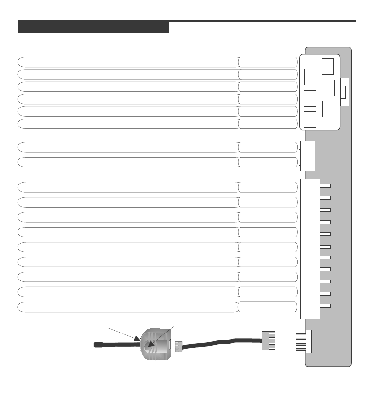
QUICK VIEW WIRE DIAGRAM
SYSTEM PROGRAMMING - Menu 1
72 SERIES
INSTALL MANUAL
OUTPUT TO ACTIVATE THE VEHICLES STARTER CIRCUIT
OUTPUT TO ACTIVATE ACCESSORY CIRCUITTHE VEHICLES
12VOLT/ 30 AMP MAIN POWER INPUT RED
12VOLT/ 30 AMP MAIN POWER INPUT RED
SELECTABLE OUTPUT* (DEFAULT 2ND IGN) SEE PAGE 11
OUTPUT TO ACTIVATE IGNITION CIRCUITTHE VEHICLES
SYSTEM GROUND INPUT
SELECTABLE PARK LIGHT OUTPUT (DEFAULT POSITIVE)
(-) REARM OUTPUT - PROGRAMMABLE - SEE PAGE 13
(-) DISARM OUTPUT (PULSE WITH UNLOCK & BEFORE START)
(-) AUXILIARY 1 OUTPUT - PROGRAMMABLE - SEE PAGE 13
(-) AUXILIARY 2 OUTPUT - PROGRAMMABLE - SEE PAGE 13
(-) HORN OUTPUT - PROGRAMMABLE - SEE PAGE 13 WHITE/BLUE
(+) BRAKE SWITCH INPUT (12VOLT WHEN BRAKE IS PRESSED)
(-) HOOD PIN SWITCH INPUT (GROUND WHEN HOOD IS OPENED)
(+ / -) TACH DETECTION INPUT (CONNECT TO COIL, INJECTOR...)
(+) GLOW PLUG - PROGRAMMABLE/ - SEE PAGE 13(+) START TRIGGER
STATUS LED
PROGRAM / VALET BUTTON
YELLOW
GREEN
WHITE*
BLUE
BLACK
WHITE
YELLOW
BROWN
BLACK
RED/WHITE
PINK
GREEN/WHITE
BLUE/WHITE
BLUE
1
2
1
2
3
4
5
6
7
8
9
DO NOT INSTALL THIS SYSTEM INTO A MANUAL TRANSMISSION VEHICLE!!
72 SERIES
INSTALL MANUAL
SYSTEM PROGRAMMING - Menu 1
PAGE 4
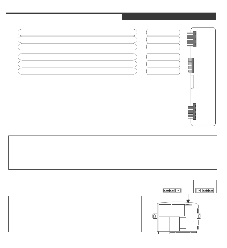
QUICK VIEW WIRE DIAGRAM
OUTPUT TO ACTIVATE DOOR LOCK CIRCUIT (-)
OUTPUT FOR VOLTAGE INVERTER*
OUTPUT TO ACTIVATE DOOR UNLOCK CIRCUIT (-)
(-) WHILE RUNNING OUTPUT (BYPASS TURN ON) / STARTER DISABLE
GROUND OUTPUT FOR BYPASS MODULE
12VOLT OUTPUT FOR BYPASS MODULE
BYPASS MODULE DATA COMMUNICATION PORT
***FOR USE WITH COMPATIBLE BYPASS MODULES ONLY***
GREEN
N/A*
BLUE
WHT/VIOLET
BLACK
RED
1
2
3
1
2
3
1
2
3
4
* THE CENTER PIN OF THE KEYLESS CONNECTOR IS LOW CURRENT AND IS DESIGNED
TO SUPPLY POWER TO DOOR LOCK MODULES (DO NOT CONNECT TO RELAYS)
OVERLOADING THIS OUTPUT WILL DAMAGE THE MODULE!
**THIS CONNECTOR IS USED FOR ALARM MODELS ONLY.
*** FOR USE WITH COMPATIBLE BYPASS MODULES ONLY.
Position 1 or Position 2
SELECTABLE PARK LIGHT OUTPUT
POSITIVE
PARK LIGHT
NEGATIVE
PARK LIGHT
BY DEFAULT THE SYSTEM COMES WITH THE PARK
LIGHT JUMPER SET FOR POSITIVE PARK LIGHT
OUTPUT. TO CHANGE THE SYSTEM TO A NEGATIVE
PARK LIGHT OUTPUT, PLACE THE JUMPER IN THE
NEGATIVE PARK LIGHT POSITION SHOWN IN THE
DIAGRAM. (Position 2)
PAGE 5
QUICK VIEW PROGRAMMING
SYSTEM PROGRAMMING - Menu 1
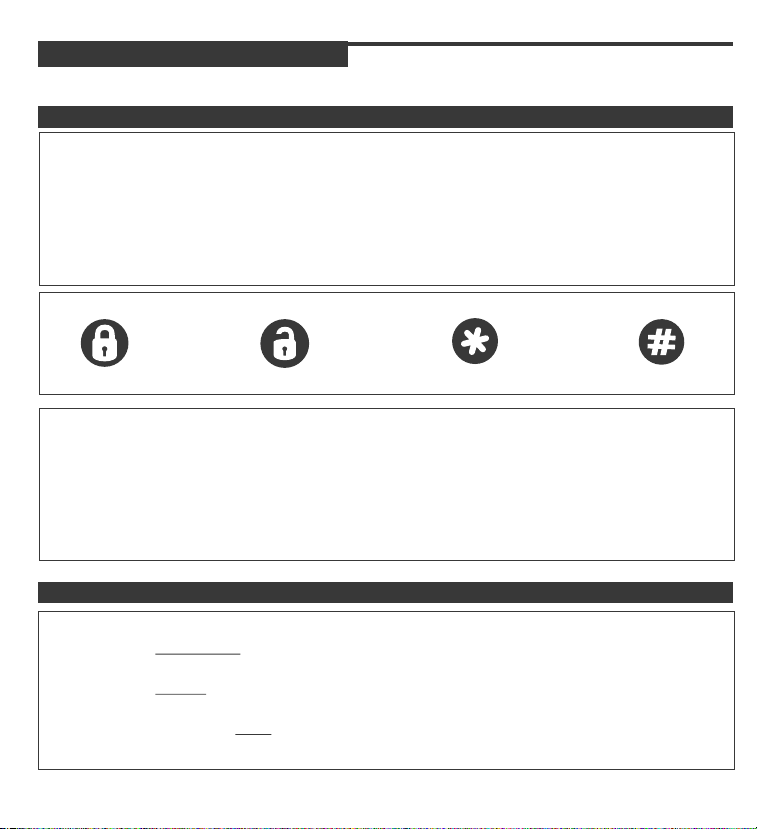
ENTERING PROGRAM MODE
1 - Cycle the Ignition Key On/Off On/Off On (Leaving the key ON)
2 - Press and release the Program Switch located on the antenna 1 time.
*The Horn will chirp and the park light will turn on to confirm that the system
has entered Program Mode.
3 - Select the Program Menu by pressing the button that corresponds to the
desired Program Menu.
72 SERIES
INSTALL MANUAL
Press Lock
Press Unlock
Press Start
Press #
MENU 1 MENU 2 MENU 3 MENU 4
4 - Press and Release the Program Switch to advance through the settings.
*The horn will chirp and LEDs flash the same number of times as the selected setting.
5 - Press and hold the Program Switch to change the setting.
(The horn will honk and the park lights will flash to indicate the option selected)
6 - To exit Program Mode, turn the key off.
(Confirmed by Long Horn Chirp)
SYSTEM RESET
1 - Cycle the Ignition Key On/Off On/Off On (Leaving the key ON)
2 - Press and RELEASE the Program Switch 1 time.
(Horn will chip to confirm program mode has been entered)
3 - Press and HOLD the Program Switch for 5 seconds or until the Horn Chirps 3
times.
4 - Turn the ignition key OFF to exit.

PAGE 6
QUICK VIEW PROGRAMMING
SYSTEM PROGRAMMING - Menu 1
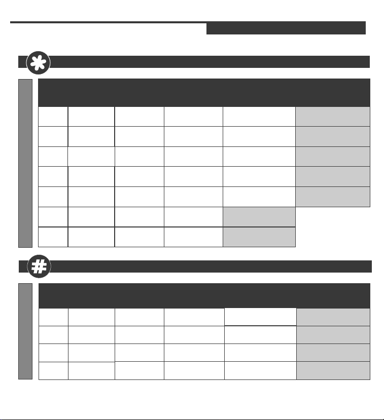
PROGRAM MODE 1 - see page 16 for detailed instructions
72 SERIES
INSTALL MANUAL
SETTING #
FLASHES
PROGRAM MODE 1
LED
1
2
3
4
5
6
WIRE COLOR
BLUE & GREEN
(DOOR LOCK HARNESS)
WHITE/BLUE
(9 PIN CONNECTOR)
BLUE & GREEN
(DOOR LOCK HARNESS)
BLUE & GREEN
(DOOR LOCK HARNESS)
BLACK
(9 PIN CONNECTOR)
RED/WHITE
(9 PIN CONNECTOR)
PROGRAM MODE 2 - see page 19 for detailed instructions
SETTING #
FLASHES
PROGRAM MODE 2
LED
1
2
3
WIRE COLOR
N / A
WHITE
(2 PIN CONNECTOR)
WHITE/BLUE
(9 PIN CONNECTOR)
PARK LIGHT OUTPUT
SETTING
DESCRIPTION
IGNITION
AUTO-LOCK
HORN SETTINGS
DOOR LOCK PULSE
OPTIONS
DOOR LOCK /
UNLOCK PULSES
AUX OUTPUT 1
AUX OUTPUT 2 DOME LIGHT OUTPUT
SETTING
DESCRIPTION
VALET SETTINGS
HORN TIMING 5MS PULSED OUTPUT 50MS PULSED OUTPUT 10MS PULSED OUTPUT
OPTION 1
1 CHIRP
IGNITION AUTO-LOCK /
UNLOCK
HORN
CHIRPS DISABLED
DOUBLE UNLOCK &
SINGLE LOCK
0.25 SEC PULSES 3 SEC PULSES 0.72 SEC PULSES
(-) ACCESSORY OUTPUT
(#) ACTIVATES CAR FINDER
OPTION 1
1 CHIRP
SECURE VALET
15 SECONDS
30 SECONDS ON
DISARM
OPTION 2
2 CHIRPS
IGNITION AUTO-LOCK
ONLY
HORN
CHIRPS ENABLED
DOUBLE LOCK & SINGLE
UNLOCK
(-) START OUTPUT
(#) ACTIVATES CAR FINDER
2ND UNLOCK
OPTION 2
2 CHIRPS
STANDARD VALET
5 SECONDS
NORMAL OPERATION
OPTION 3
3 CHIRPS
IGNITION AUTO-LOCKS
DISABLED
SINGLE LOCK & SINGLE
UNLOCK
AUX CHANNEL (#)
TRUNK RELEASE
OPTION 3
3 CHIRPS
72 SERIES
INSTALL MANUAL
PROGRAM MODE 3 - see page 21 for detailed instructions
SYSTEM PROGRAMMING - Menu 1
PAGE 7
QUICK VIEW PROGRAMMING
SETTING #
LED
FLASHES
PROGRAM MODE 3
WIRE COLOR
1
2
3
4
5 N / A
6 N / A
7 N / A
WHITE
(6 PIN CONNECTOR)
BLUE & GREEN
(DOOR LOCK CONNECTOR)
BLUE
(9 PIN CONNECTOR)
YELLOW
(9 PIN CONNECTOR)
SETTING
DESCRIPTION
SELECTABLE
RELAY
SPECIAL DOOR
LOCK OPTIONS
GLOW PLUG/
START TRIGGER
RE-ARM OPTIONS PULSE WITH LOCK
RUNTIME 4 MINUTE RUNTIME
REMOTE START
ACTIVATION
LED FLASHES
OPTION 1
1 CHIRP
2ND
STARTER
UNLOCK BEFORE /
LOCK AFTER START
(-) GLOW PLUG OR 20
SECONDS DELAY
PRESS BUTTON TWICE
TO START
LEDS DO NOT FLASH
WHEN LOCKED/
ARMED
PROGRAM MODE 4 - see page 23 for detailed instructions
SETTING #
LED
FLASHES
PROGRAM MODE 4
WIRE COLOR
BLUE / WHITE
1
(9 PIN CONNECTOR)
2 N / A
3 N / A
4 N / A
SETTING
DESCRIPTION
TACH OPTIONS HYBRID MODE 1
ADJUST FOR
OVER-CRANK
ADJUST FOR
UNDER-CRANK
TACH WAIT
SETTINGS
OPTION 1
1 CHIRP
INCREASES TACH
SETTING BY 10%
DECREASE TACH
SETTING BY 10%
300ms TACH CHECK
DELAY
OPTION 2
2 CHIRPS
2ND ACCESSORY
LOCK AFTER STARTER SHUT
OFF
POSITIVE TRIGGER TO
START (1 PULSE)
PULSE AFTER START
(DEFROST / SEAT)
45 MINUTE RUNTIME 15 MINUTE RUNTIME
PRESS BUTTON ONCE TO
START
LEDS FLASH WHEN
LOCKED/ ARMED
OPTION 2
2 CHIRPS
HYBRID MODE TWO
750ms TACH CHECK DELAY
OPTION 3
3 CHIRPS
2ND
IGNITION
NO ADDITIONAL PULSES
GAS/ POSITIVE GLOW PLUG
PULSE WITH LOCK & AFTER
SHUTDOWN
OPTION 3
3 CHIRPS
AUTO TACH / TACHLESS
NO TACH CHECK DELAY
72 SERIES
INSTALL MANUAL
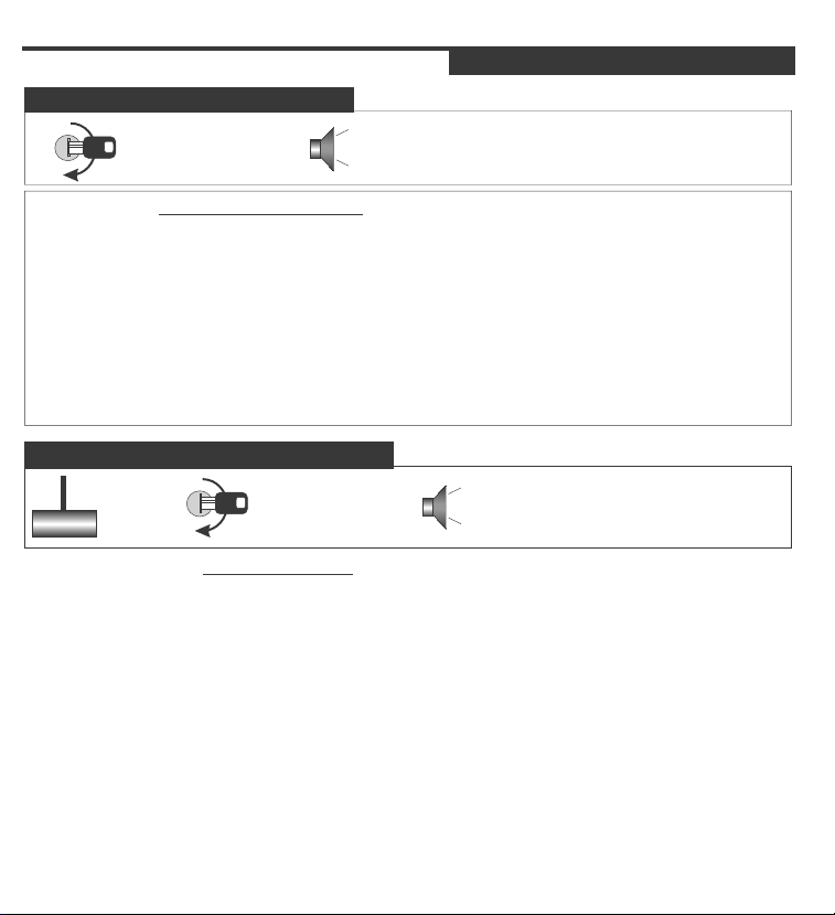
AUTO TACH/ TACHLESS LEARNING
Start the vehicle with
the ignition key.
**For Vehicles with 12volt START wire**
2 CHIRPS
4 CHIRPS
SYSTEM PROGRAMMING - Menu 1
TACH / TACHLESS LEARNING
Horn will chip to confirm that
the Tach/ Tachless has been programmed.
PAGE 8
To Tach/ Tachless Learn the system simply start the vehicle with the ignition key. To
confirm that a proper Tach signal has been programmed the system will chirp the
Horn and flash the Park lights two times. If the Tach wire is not connected the park
lights will flash and the Horn will chirp 4 times to indicate Tachless Mode. If the Tach
is not learned when the start button is pressed the park lights will flash 7 times.
***The system must be Tach Learned before remote starting***
MANUAL TACH/ TACHLESS LEARNING
Start the vehicle with
the ignition key.
BRAKE
Hold the
brake
**For vehicles with no 12volt START wire**
Many new GM and Chrysler vehicles do not have a 12volt start wire that the remote
2 CHIRPS
4 CHIRPS
SYSTEM PROGRAMMING - Menu 1
Horn will chip to confirm
that the Tach/ Tachless has been
programmed.
start is connected to. Use the following steps to manually Tach learn the system.
Press and Hold the brake pedal, Start the vehicle with the key then place the
transmission into reverse to reduce the RPM. Press and release the program button
then press and hold it for 5 seconds. The Horn will chirp and the lights will flash
two times to confirm that a proper Tach signal has been programmed the system.
If the Tach wire is not connected the park lights will flash and the Horn will chirp 4
times to indicate Tachless Mode. If the Tach is not learned when the start button is
pressed the park lights will flash 7 times.
***The system must be Tach Learned before remote starting***
PAGE 9
TACH / TACHLESS LEARNING
SYSTEM PROGRAMMING - Menu 1
TACH NOTES
* If the vehicle does not have a starter wire a manual tach learn must be
preformed. (See Page 8)
** If Tach does not learn check for proper connection on the starter wire,
ignition wire and at the Tach connection. If the connections are good, reset
the system and try again.
-For best results connect the Tach wire to a fuel injector wire.
*** If the vehicle does not start when the remote starter is activated, the park
lights will flash a diagnostic code. (See Diagnostic Chart).
****If the vehicle still does not start, check all connections and check for a
factory installed Anti-Theft system. If the Anti-Theft prevents the vehicle from
starting the remote start will flash the park lights 7 times. The system does not
have to be Tach learned if this happens, simply start the vehicle with the key
and let it run for 5 seconds then turn off.
72 SERIES
INSTALL MANUAL
 Loading...