

Ultra Start 1256M SERIES Installation Manual
REMOTE STARTERS
CAR ALARMS
U.S.A. Model
INSTALL GUIDE
This Manual Covers All 1250 Series
Transmission
Remote Starters
Manual
ü
WWW.ULTRASTARTERS.COM
Technical Support 866-698-5872 ext 0
Support@ultrastarters.com
-The system must be placed into Service Mode before any service work is started on
the vehicle. It is the sole responsibility of the vehicle owner to ensure that this is done.
The manufacturer accepts no liability or responsibility for accidental starting of the
vehicle.
- CARBON MONOXIDE - Never Start in an Enclosed Building (Garage, Carport etc...)

Installation Guide Page 2
1250/M Wiring Diagram Page 3
Pre-Installation Page 4
Components
Pre Installation Check
Installation Procedures
Wire Connectors Page 5
6 Pin Connector
14 Pin Connector
3 Pin Red Connector
Jumper Positions
Installation Page 6
Basic Installation - Quick start
Plug-In The Module
Auto Tach Learn
Programming Page 7-10
Program Overview
Reset The System To Factory Defaults
Program Menu 1 (User Settings)
Program Menu 2 (Additional Settings)
Program Menu 3 (Starter Settings)
Program Menu 4 (Tach Settings)
Operations Page 10
Manual Transmission (Reservation Mode)
Additional Operations Page 11
Transmitter Programming
1st & Second Car Transmitter Programming
Emergency System Service Mode
Battery Replacement
Relay Diagrams Page 12
Diagnostics
PARK LIGHTS STATUS LED DIAGNOSTIC CODE
3 Flashes Series of 3 Flashes Door Opened “M” Models
3 Slow Flashes LED’s On Solid System Is In Service Mode
4 Slow Flashes Series of 4 Flashes Not in Reservation Mode “M” units
5 Flashes Series of 5 Flashes Brake Pedal Shutdown
5 Slow Flashes Series of 5 Flashes Ignition On During StartAttempt
6 Flashes Series of 6 Flashes Hood Pin Grounded
7 Flashes Series of 7 Flashes Tach Lock-Out
8 Flashes Series of 8 Flashes 3 StartAttempts With No Start
If the remote starter has a failed start attempt or if a safety input is activated the Diagnostic Memory will store up to
four shutdowns in memory. This information can then be accessed to determine the source of the shutdown.
To Enter Diagnostic Mode:
Step 1 - Turn the ignition on wait two seconds then turn off. Press the Program Button and release.
Step 2 - The system will respond with three park light flashes and the horn will honk (optional) the
same number of times as the events in memory. ( Maximum four events, four honks)
NOTE: If the horn does not honk, there are no events in memory.
Step 3 - Press the Program Button once to view the last shut down code. The (optional) Horn will honk once to
confirm code one. (If the horn does not honk, there are no codes in memory).
Step 4 - The LED’s on the antenna will flash a code corresponding to a shut down trigger. Press the
Program Button again to check the second code. The horn will honk twice to confirm code two.
Step 5 - To Clear Diagnostic Memory. While in Diagnostic Mode press and hold the Program Button for
five seconds. The park lights will flash and the horn(optional) will honk once.
NOTE: Once diagnostic memory has 4 shutdown events in memory, the system will not record any further
shutdown events until the system memory has been cleared.
Page 3 Installation Guide
Starter
Heater
Power
Power
Jumper Selectable
Ignition 1
1
2
3
4
5
6
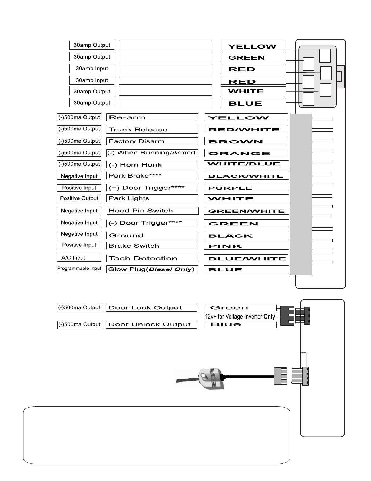
**** These connection’s are only necessary for installation’s on manual transmission
vehicles. Always install a “M” Series Remote Starter on manual transmission vehicles.
Note: Do not use the center pin of this connector to power relay packs. Doing so will
damage the output. Always use a fused power source when installing relays for
keyless entry.
Program Button
Status Led’s
ACTIVE RF ANTENNA
Note: The antenna must be connected before the system will operate.
FCC/ID Notice
This device complies with Part 15 of the FCC rules. Operation is subject to the following conditions:
(1) This device may not cause harmful interference, and
(2) This device must accept any interference received, including interference that may cause undesired
operation.
CAUTION: Changes or modifications not expressly approved by the part responsible for compliance void
the user’s authority to operate this devise.
3
P
I
N
RED
4N
PI
B
lue

Installation Guide Page 4
Components
- Control module
- Remote transmitter(s)
- Antenna with built in Program Button and LED’s
- 6 pin main harness with dual 30amp power inputs.
- 14 pin harness
- 3 pin keyless entry harness
- Hood pin safety switch
- Installation guide
Recommended Pre-Installation Procedures
BEFORE STARTING INSTALLATION:
- Discuss the optional features with the customer.
- Take a few minutes to review the installation and owners manuals.
- Check if the vehicle has a factory security or anti-theft system.
*If equipped, inform the customer of addition parts and labour.
- Do a walk around the vehicle and check for any damage.
- If installing a LED discuss the placement with customer before installing.
Recommended Installation Procedures
Proper Connections - Remote Starters can handle loads of up to 30 amps for extended periods
of time. It is CRITICAL to insure that ALL high current connections are properly soldered and
insulated with quality electrical tape. Failing to insure proper connections will result in warranty
being VOID and can result in a FIRE. The manufacturer is not responsible for any such damages.
It only takes a few more minutes to do the job RIGHT.
Under Hood Connections - Route the hood pin and tach wires through the firewall into the
engine compartment. Always try to pull the wires through a factory rubber grommet. If drilling
through the firewall, BE CAREFUL. Check for obstructions on both sides of the firewall. After
drilling use a snap in grommet to protect the wires from sharp edges.
Installing the External Long Range Antenna - To insure the best possible reception, place the
antenna in the center of the windshield, behind the rear view mirror. Before attaching to the glass
ensure that the surface is clean and dry. For best results with range, place the antenna below the
tint screen. Run the cable under the head liner and behind the A-pillar panel. Be careful not to
pinch the antenna cable. Plug the antenna into the BLUE connector on the Control Module.
Mounting The Control Module - Never mount the module in the engine compartment. Select a
location under the dash to install the main module. Be certain that the module is securely attached
and does not obstruct any serviceable areas. Do not force or jam the module into tight places
instead of mounting. The module must be free from all moving parts such as brake, clutch and
gas pedals linkages. Do not place the module directly in front of a heater vent.
Testing The System - When the installation is complete, it will be necessary to test that the
system is working correctly. The system’s default programming will work on the majority of
vehicles, but might need to be adjusted for some applications. If the installation requires special
timing or additional features, proceed to Program Mode.
ATTENTION: The Hood Pin Switch MUST always be connected!!
Note: Always inform user to place system in Service Mode before any service work is
performed on the vehicle.
 Loading...