

INSTALL GUIDE
U.S.A. Model
1150 Series Remote Starters
REMOTE STARTERS
CAR ALARMS
ü
WWW.ULTRASTARTERS.COM
-The system must be placed into Service Mode before any service work is started on
the vehicle. It is the sole responsibility of the vehicle owner to ensure that this is done.
The manufacturer accepts no liability or responsibility for accidental starting of the
vehicle.
- CARBON MONOXIDE - Never Start in an Enclosed Building (Garage, Carport etc...)

INSTALLATION MANUAL
REMOTE VEHICLE STARTER
Page 2
Components
- Control module - Hood pin safety switch
- 6 pin main harness with dual 30amp power inputs .- 14 pin harness
- 2 Pin keyless entry harness - Installation guide
- LED/Program Switch
Diagnostics
PARK LIGHTS STATUS LED DIAGNOSTIC CODE
3 Slow Flashes LED’s On Solid System Is In Service Mode
5 Flashes Series of 5 Flashes Hood Pin Opened
5 Slow Flashes Series of 5 Flashes Ignition On During Start Attempt
6 Flashes Series of 6 Flashes Brake Pedal Shutdown
7 Flashes Series of 7 Flashes Tach Lock-Out
8 Flashes Series of 8 Flashes 3 Start Attempts with no start
Diagnostic Memory- With Program LED/Switch.
If the remote starter has a failed start attempt or if a safety input is activated the Diagnostic Memory will store
up to four shutdowns in memory. This information can then be accessed to determine the source of the
shutdown.
To Enter Diagnostic Mode:
Step 1 - Turn the ignition on wait two seconds then turn off. Press the Program Button and release.
Step 2 - The system will respond with three park light flashes and the horn will honk (optional) the
same number of times as the events in memory. ( Maximum four events, four honks)
NOTE: If the horn does not honk, there are no events in memory.
Step 3 - Press the Program Button once to view the last shut down code. The (optional) Horn will honk once
to confirm code one. (If the horn does not honk, there are no codes in memory).
Step 4 - The LED’s will flash a code corresponding to a shut down trigger. Press the Program Button again
to check the second code. The horn will honk twice to confirm code two.
Step 5 - To Clear Diagnostic Memory. While in Diagnostic Mode press and hold the Program Button for
five seconds. The park lights will flash and the horn(optional) will honk once.
NOTE: Once diagnostic memory has 4 shutdown events in memory, the system will not record any
further shutdown events until the system memory has been cleared.
System Service Mode (Valet Mode)
Service Mode is to used when the vehicle is having service work preformed on the vehicle.
Service Mode will disable the remote starter from activating until the service mode is
Deactivated.
ACTIVATING Service Mode
1.While the ignition is “ON” press and hold the Program Button for five seconds. The park lights
will flash five times and the horn (optional)will honk five times to confirm that the system is in
Service Mode.
2. While in Service Mode the remote start functions will be disabled and LED’s will be “ON”
steady. Door locks and trunk release are still operational.
DEACTIVATING Service Mode
1. While the ignition is “ON” press and hold the Program Button for five seconds. The park lights
will flash two times and the horn (optional)will honk two times to confirm that the system has
exited Service Mode.
2. Remote start functions will return to normal operation.
REMOTE VEHICLE STARTER
INSTALLATION MANUAL
Page 3
N/A
N/A
* Connect only one of these wires for remote start activation. The input requires 2
pulses within 2 seconds to activate.
Not used on this model
Negative When Running
Not used on this model
Positive Start Trigger*
Negative Start Trigger*
Program LED/Switch
The jumpers control the output from the white wire from the six pin
harness. Place the jumpers in the following order to change the output.
Note: The default setting is second ignition.

INSTALLATION MANUAL
REMOTE VEHICLE STARTER
Page 4
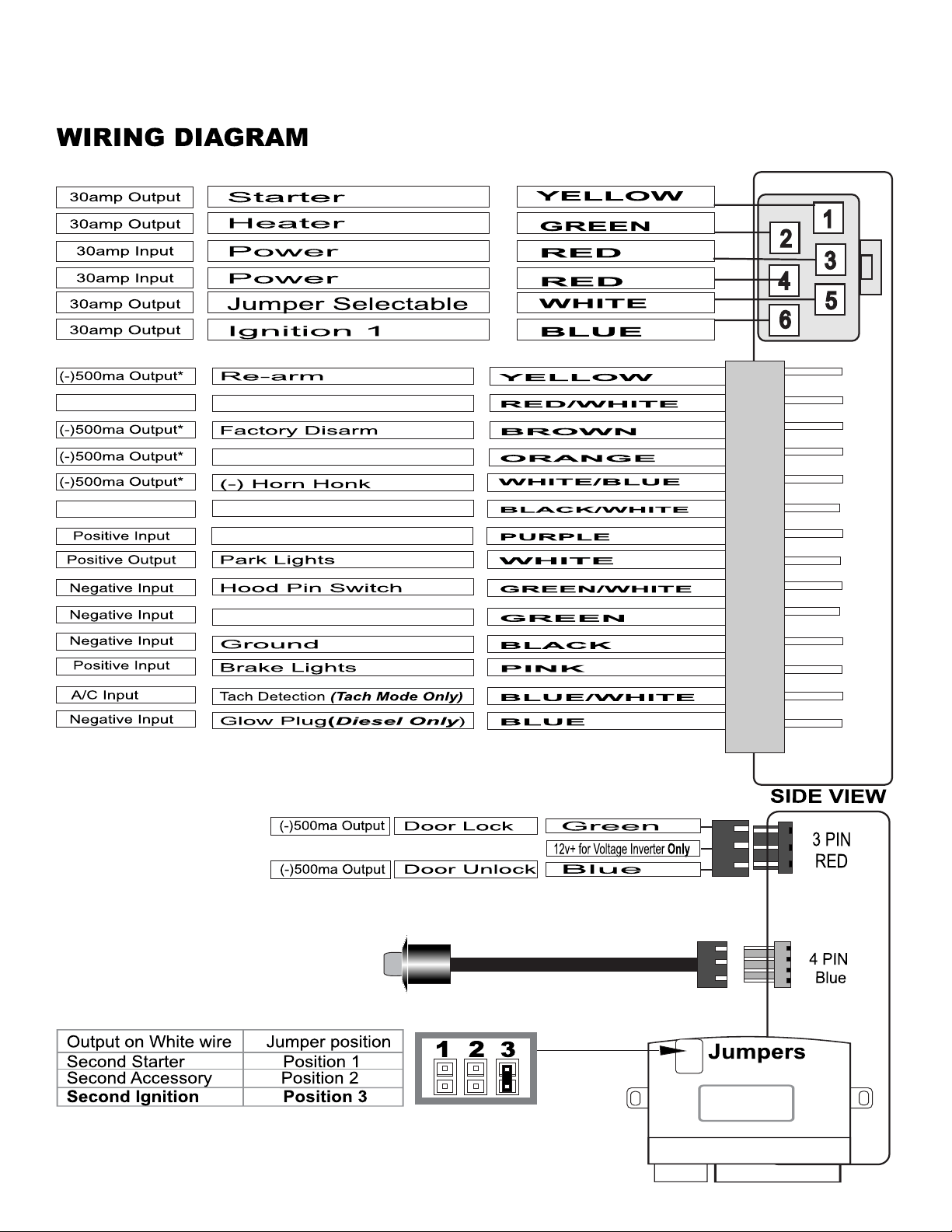
WIRING CONNECTIONS
6 Pin Power Connector
Yellow Starter 30amp output 12volts during crank only.
Green Heater 30amp output 12volts in accessory off during start.
Red 12 power 30amp input Constant 12volt power at ignition harness.
Red 12 power 30amp input Constant 12volt power at ignition harness.
Blue Ignition 1 30amp output 12volts in ignition and start positions.
White Select Output 30amp output Selectable Output. See jumper diagram.
14 Pin Connector
Yellow Re-Arm 0.75sec Pulse On Shutdown. (500ma Output)
Red/White N/A Not Used on this model.
Brown Disarm 0.75sec Pulse With Unlock And Before Start.(500ma Output)
Orange (-) Output (-) While Running
White/Blue Horn (-) Horn Honk Output
Black/White N/A Not Used on this model.
Purple (+) Start Connect to positive start input.
White Park Lights Positive Park light Output - 10 Amp Max.
Green/White Hood Pin Negative Hood Pin Input - MUST BE CONNECTED!!
Green (-) Start Connect to negative start input.
Black Ground System Ground Input - MUST BE CONNECTED!!
Pink Brake Positive Brake Input - MUST BE CONNECTED!!
Blue/White Tach Tach Signal Input - Must be connected for Tach Mode!!
Blue Glow Plug Programmable Input - DIESEL ONLY.
* Connect only one start input. The start input will require 3 negative pulses within 2 seconds
To activate the remote starter.
Note: 500ma outputs are low current and are designed to activate relays.
4 Pin Connector Blue - Program LED/ Switch
Program LED/Switch connector. The program switch is integrated into the LED. Press the LED to
activate the switch.
Jumper Selections
Position One Second Starter Output On the White Wire From The 6-Pin Connector.
Position Two Second Accessory Output On The White Wire From The 6-Pin Connector.
*Position Three Second Ignition Output On The White Wire From The 6-Pin Connector.
* The Default Setting For The System Is Second Ignition Output.
The jumpers control the output from the white wire at the 6-pin harness. Place the jumper in the following
positions to change the output.
Note: The default jumper setting is second ignition.
Output on White wire Jumper position
Second Starter Position 1
Second Accessory Position 2
Second Ignition Position 3

REMOTE VEHICLE STARTER INSTALLATION MANUAL
Page 5
QUICK START INSTALL
Step 1 - Connect All Of the Following Wires
6 Pin Power Connector
Yellow Starter Output Connect To The Vehicles Starter Wire.
Green Heater Output Connect To The Vehicles Accessory Wire.
Red 12 power Input Connect to Constant 12 Volt Power Source- High Current.
Red 12 power Input Connect to Constant 12 Volt Power Source- High Current.
Blue Ignition 1 Output Connect To the Vehicles Primary Ignition.
White Selectable Output Select Jumper Position (If Necessary). See Page 5.
14 Pin Power Connector
Black System Ground Connect To Chassis Ground.
Pink Brake Switch Connect To (+) When The Brake Pedal Is Applied.
White Park Lights Connect To (+) Park Light System.
Green/White Hood Pin Connect To Hood Pin Switch. (Must Be Connected)
Blue/White Tach Connect To A/C Tach Souse (Tach Mode Only)
Green* (-) Start Connect to Negative start activation input.
Purple * (+) Start Connect to Positive start activation input.
* Connect only one start input. The start input will require 3 negative pulses within 2 seconds to
activate the remote starter.
** The start input can be connected to such things as factory keyless entry (Connect to unlock wire)
or an auxiliary output from a aftermarket alarm system.
Step 2- Auto Tach/ Tachless Learning (TL Models)
TACH LEARNING
1) Make all the required wire connections and plug-in the Unit.
**The park lights should flash twice upon power up.
2) Turn the Ignition Key ON. (The Park Lights will turn on).
3) Start the vehicle with the key, the program LED will come when proper tach signal is detected.
After 30 seconds the park lights will turn off then flash twice to confirm Tach learning.
* The system will flash the park lights seven times if not Tach/ Tachless learned and the start button
is pressed. The system must be Tach/ Tachless learned before remote starting.
** If the program LED does not come on during tach learn, a proper Tach signal was not detected.
Note: If the park lights do not flash in Auto Tach Learn Mode it may be necessary to connect
to a different tach source. For best results connect the tach to the coil pack or to a fuel
injector wire.
TACHLESS LEARNING (TL Models Only)
1) Make all the required wire connections and plug-in the Unit.
**The park lights should flash twice upon power up.
2) Turn the Ignition Key ON. (The Park Lights will turn on).
3) Start the vehicle with the key, the program LED will turn on after 30 seconds then the park lights
will turn off and flash twice to confirm Tachless learning.
Note: If the first ignition wire is connected to a wire that does not stay 12 volts in the start
position the system will not Tach/ Tachless learn.
***The system must be reset to re-Tach/Tachless learn.
Your Basic Install Is Complete!

INSTALLATION MANUAL
REMOTE VEHICLE STARTER
Page 6
Programming Overview
Program mode allows you to adjust the settings and options of your system. Your system has been
intelligently designed by installers with years of experience. The system’s default settings do not require any
program changes in most cases. However, this system does incorporate a highly advanced programming
system that can be easily adjusted for custom installations and applications.
Entering Program Mode
1) Make sure ignition is in the off position.
2) Within three seconds turn the key ON - OFF - ON - OFF - ON. Leave in the “ON” position.
3) Press and release the Program Button.
4) The park lights will come on and the horn (optional) will honk to confirm Program Mode.
* Turning off the ignition or 30 seconds of no activity will exit the Program Mode. This will be
confirmed by 1 long horn honk and park light flash.
**: If the unit does not enter Program Mode, turn ignition off for 5 seconds and repeat steps 1-4. **
The first ignition(Blue)MUST be connected to the vehicle’s first ignition wire. If it is not connected
It will not be possible to enter the Program Modes.
Changing the Programmable Settings
1) Enter Program Mode. (See Above)
2) Press & release the Program Button the correct number of times to select the desired
Program Setting. The LED’s will flash and the horn (optional) will honk to indicate the current
setting that is selected.
4) Hold the Program Button until the parking lights /horn confirm the selected setting. The park
lights will flash and the horn (optional) will honk to indicate the option selected within the setting.
5) Turn the ignition key “Off” to exit Program Mode.
SYSTEM RESET
In some cases it may be necessary to reset the system to it’s default settings. The system reset
will change all program settings to there default setting (Bold Text). A system reset must also be
preformed when the tach setting is to be re-learned.
1) Within 3 seconds turn the key ON-OFF-ON-OFF-ON (Leaving Key ON).
2) Press and release the Program Button.
3) The park lights will turn ON and the horn(Optional) will honk once.
4) Press the Program Button a second time and hold for 8 seconds.
The park lights will flash and the horn (Optional) will honk 3 times.
The System is now re-set to the factory default settings.

REMOTE VEHICLE STARTER
INSTALLATION MANUAL
Page 7
Programming Menu
Turn the ignition key to the on position 3 times then press and release the program button. The park lights
will turn on and the horn(Optional) will honk once. While the park lights are on press and release the program
button until the LED is flashing the same number of times as the program setting that is to be changed.
Press and hold the program switch until the park lights flash the correct number of times as the option to be
programmed.
Setting 1- Special Door Lock/ Unlock Operations
1 Type 1 1 Flash Unlock before start. Lock pulse after start and shutdown
2 Type 2 2 Flashes Lock pulse only after remote starter shuts off
3* Normal Operation 3 Flashes No additional re-lock pulses
Press the Program Button 1 time to select setting 1 (This will be confirmed by 1 LED flash)
Press and hold the Program Button until you receive the appropriate # of park light flashes and
horn honks.
Release the Program Button . Press momentarily to move to next program step or repeat to
change selection.
Setting 2- Gas/ Diesel Mode- Blue Wire on 14-Pin
1 Negative Input/ 30seconds 1 Flash Waits a maximum 30 seconds before starting.
2 Timed Delay/ 15 Seconds 2 Flashes Ignition ON for 15 seconds before engaging remote starter
3* Gas/ Positive Glow Plug 3 Flashes Waits 2 seconds to start if no diesel input is detected
Press the Program Button 2 time to select setting 2 (This will be confirmed by 2 LED flashes)
Press and hold the Program Button until you receive the appropriate # of park light flashes and horn honks.
Release the Program Button . Press momentarily to move to next program step or repeat to change selection.
Setting 3- Rearm Output- Yellow Wire on 14-Pin
1 Type 1 1 Flash Pulse after start and with lock
2 Type 2 2 Flashes Pulse after start only
3* Factory Re-arm 3 Flashes 0.75 second pulse with lock and after shutdown
Press the Program Button 3 times to select setting 3 (This will be confirmed by 3 LED flashes)
Press and hold the Program Button until you receive the appropriate # of park light flashes and/or horn honks.
Release the Program Button. Press Program Button momentarily to move to next program step or repeat to
change selection.
Setting 4- Run Time
1 30 Min Run Time 1 Flash Remote Starter runs for 30min when activated
2 45 Min Run Time 2 Flashes Remote Starter runs for 45min when activated
3* 15 Min Run Time 3 Flashes Remote Starter runs for 15 min when activated
Press the Program Button 4 times to select setting 4 (This will be confirmed by 4 LED flashes)
Press and hold the Program Button until you receive the appropriate # of park light flashes and/or horn honks.
Release the Program Button. Press Program Button momentarily to move to next program step or repeat to
change selection.
Continued on next page.....

INSTALLATION MANUAL
REMOTE VEHICLE STARTER
Page 8
See page 6 for Entering Program Mode.
Setting 5-Maximum Crank Time
1 10 Seconds 1 Flash 10 sec Max time that starter will stay engaged
2 3 Seconds 2 Flashes 3 sec Max time that starter will stay engaged
3*5 seconds 3 Flashes 5 sec Max time that starter will stay engaged
Press the Program Button 5 times to select setting 5 (This will be confirmed by 5 LED flashes)
Press and hold the Program Button until you receive the appropriate # of park light flashes and/or horn honks.
Release the Program Button. Press Program Button momentarily to move to next program step or repeat to
change selection.
Setting 6- Tach Selection
1Tach Detection Mode 1 Flash Set for Tach Detection - Must Connect Tach Wire
*2Tachless Mode 2 Flashes No Tach connection required
Press the Program Button 6 times to select setting 6 (This will be confirmed by 6 LED flashes)
Press and hold the Program Button until you receive the appropriate # of park light flashes and/or horn honks.
Release the Program Button. Press Program Button momentarily to move to next program step or repeat to
change selection
Setting 7- Adjust For Over-Crank
1 - Enter Program Mode (Ignition ON-OFF-ON-OFF-ON) then press the Program Button.
2 - Press the Program Button - 7 times (Led will start flashing 7 times).
3 - Hold the Program Button - For 5 seconds until parking lights flash (each time lights flash tach is reduced).
4 - Release the Button - Exit Program Mode and remote start to test.
Setting 8- Adjust For Under-Crank
1 - Enter Program Mode (Ignition ON-OFF-ON-OFF-ON) then press the Program Button.
2 - Press the Program Button - 8 times (Led will start flashing 8 times).
3 - Press and Hold Program - For 5 seconds until parking lights flash (each time lights flash tach is increased ).
4 - Release Program - Exit Program Mode then remote start to test.
Setting 9- Start Trigger Input- Number of pulses to activate Remote Starter
1 Pulse Once 1 Flash One pulse required to activate the remote starter.
*2Pulse Twice 2 Flashes Two pulses required to activate the remote starter.
Press the Program Button 9 times to select setting 9 (This will be confirmed by 9 LED flashes)
Press and hold the Program Button until you receive the appropriate # of park light flashes and/or horn honks.
Release the Program Button. Press Program Button momentarily to move to next program step or repeat to
change selection
 Loading...