

Ultrasound Technologies Fetatrack 310 User manual
Ultrasound Technologies Ltd
Fetatrack 310
Service Manual
Issue 1

Ultrasound Technologies Ltd
Contents
INTRODUCTION......................................................................................................3
Specification ........................................................................................................................................................4
User Configuration.............................................................................................................................................6
SAFETY IN USE.......................................................................................................7
Special Precautions.............................................................................................................................................7
Electrical Shock Hazard.................................................................................................................................... 7
Explosion Hazard.............................................................................................................................................. 8
Handling the Delicate Transducers................................................................................................................... 8
Symbols used.................................................................................................................................................... 9
REFERENCE .........................................................................................................10
FETATRACK 310 front panel controls..........................................................................................................10
Recorder On/Off............................................................................................................................................. 10
Front Panel Event Mark.................................................................................................................................. 10
Volume Up...................................................................................................................................................... 10
Volume Down................................................................................................................................................. 10
US1 / US2 Transducer Select ......................................................................................................................... 10
Toco Zero ....................................................................................................................................................... 10
Indicators and Connectors...............................................................................................................................11
Power on Indication........................................................................................................................................ 11
RS232 output.................................................................................................................................................. 11
Remote (patient) Event Marker....................................................................................................................... 11
Probe Connection............................................................................................................................................ 11
Internal Layout.................................................................................................................................................12
Dismantling Procedure.................................................................................................................................... 12
Circuit Description ...........................................................................................................................................13
Power supply Circuit....................................................................................................................................... 13
Ultrasound Circuit........................................................................................................................................... 14
Audio Amplifier.............................................................................................................................................. 14
Signal Pre-processing...................................................................................................................................... 15
Toco Circuit.................................................................................................................................................... 15
Microprocessor Circuit................................................................................................................................... 16
Printer Interface .............................................................................................................................................. 16
Test Procedures.................................................................................................................................................17
Introduction..................................................................................................................................................... 17
Performance Checks....................................................................................................................................... 17
Test Procedure.......................................................................................................Error! Bookmark not defined.
Parts Lists and Drawings.................................................................................................................................23
©Ultrasound Technologies Ltd Issue 1 December 2004 Page 2

Ultrasound Technologies Ltd
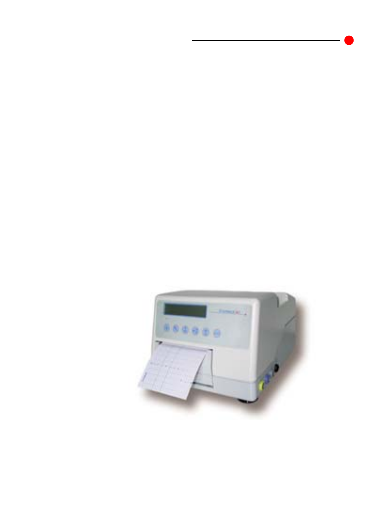
This booklet explains the operation and service of the FETATRACK 310
Antenatal Cardiotocograph. Care has been taken during the design and
manufacture of this product so that it meets all of the current safety
standards set down by IEC601-1 : 1988.
If you require assistance understan ding any part of this document, or have
any questions relating to the operation of the FETATRACK 310 please
contact:
Ultrasound Technologies Ltd
Lodge Way
Caldicot
NP26 5PS
UK
Tel +44 (0) 1291 425425
Fax +44 (0) 1291 427093
EMAIL service@doppler.co.uk
This service manual contains circuit d escrip tion s, di agrams, parts and spares
lists is available for the FETATRACK 310 that are correct at the time of
printing. Due to continuous improvement certain sections may differ in
newer units if you have any doubt please contact the address above.
To maintain the FETATRACK 310’s performance it is recommended that it
be included in a periodic maintenance programme.
©Ultrasound Technologies Ltd Issue 1 December 2004 Page 3

Ultrasound Technologies Ltd
Specification
Ultrasound
Frequency 1.8 and 2.1 MHz continuous wave
Transducer Multi element wide angle
Audio Response 300 - 1 Khz
Range 50 - 210 bpm (European), 30 – 240 bpm (Americas)
Power Output <20mW/cm2
Indicators LCD heart rate and pulse indication
Toco
Transducer Differential External pressure transducer
Response 0 - 5 Hz
Scale 0 - 100
Indicators LCD Toco level indication
Data Presentation
strip chart recorder and alphanumeric / graphic display module.
Printhead 104mm thermal solid state printhead
Resolution 8 dots / mm
Speeds 1,2,3,cm/min
Paper Z fold pre-printed chart scale
Paper type Plain black thermal
Display 32 character by 2 line LCD display module
Keys 6 Keys (for paper start /stop, Volume up ,
Volume down, HR1/2, Toco Zero and Event.)
Indicators Green power on/ off
Data Storage
Paper Out 30 min out paper storage with power connected
Data File (optional) In excess of 48 hours of full resolution data
Upto 16 separate patient files with storage limit.
Power Supply
AC input voltage 200 - 260 VAC or 100 - 130 VAC (User selected)
Frequency 46 - 64 Hz
Power 60VA
Enclosure
Material Aluminum.
Safety
Classification Class 1 Type B IEC60601-1
Computer interface
Transfer 3 wire RS232
Data Rate 9600 baud
Data Standard 8 bits no parity 1 stop bit
©Ultrasound Technologies Ltd Issue 1 December 2004 Page 4

Ultrasound Technologies Ltd
©Ultrasound Technologies Ltd Issue 1 December 2004 Page 5

Ultrasound Technologies Ltd
User Configuration
Firstly connect the AC supply cord.
It is necessary to set the operation of the FETATRACK 310 to meet your requirements.
Before turning the FETATRACK 310 on, press and hold down the Toco Zero button. Then, whilst
keeping the Toco Zero button pressed down, turn the FETATRACK 310 on by flicking the AC input on/off
switch which is located on the rear of the unit as part of the AC line input socket. When the unit is on
the front panel LED
will be illuminated.
The FETATRACK 310 starts and then enters its User Configuration Mode, release the
Toco Zero button as soon as ‘Calibrate System’ is displayed .
You are then prompted to enter the date if different to that displayed.
To change the day and month press the Volume Up button. One press advances the
day by one, pressing the Volume Up button for longer advances the day by 10.
To change the year press the Volume Down button. One press advances the year by
one, pressing the Volume Down button for longer advances the year by 10.
When the correct date is displayed press the Toco Zero button once.
You are then prompted to enter the time if different to that displayed.
This works in a similar manner to the date with the Volume Up button advancing the
hours and the Volume Down button advancing the minutes.
When the correct time is displayed press the Toco Zero button once.
You are then prompted to enter the Toco Base Line offset.
This sets an artificial zero line for the toco transducer above zero, it can be set by
pressing the Volume Up or Volume Down buttons for a value between 0 - 20.
After setting this value the Toco will be set to this every time the Toco Zero switch is
pressed, and allows small negative Toco excursions to be seen on the chart.
When the correct time is displayed press the Toco Zero button once.
You are then prompted to enter the Toco Filter Value.
This sets the filtering within the monitor to produce a smoother Toco trace if required.
( The filter can remove some of the maternal breathing artefact). It is set by pressing
the Volume Up button for a value soothing value between 1sec and 2sec..
When the correct filter value is displayed press the Toco Zero button once.
You are then prompted to enter the Toco Range.
This sets the response of the Toco transducer to either a full scale of 100 or 200 on the
chart print out. It is set by pressing the Volume Up button for a value between 100 and
200..
When the correct range is displayed press the Toco Zero button once.
©Ultrasound Technologies Ltd Issue 1 December 2004 Page 6

Ultrasound Technologies Ltd
You are then prompted to enter the Chart recorder speed.
This sets the initia l tur n-on sp eed of the char t re co rd er. T hen o nce the c hart is r unning
the speed can be further changed to 1 ,2 or 3 cm/min. It is set by pressing the Volume
Up button for a value of 1, 2 or 3 cm/min..
When the correct speed is displayed press the Toco Zero button once.
You are then prompted to select the Data Block on or off.
The Data Block is printed at the start of each recording, this function can be disabled
by setting Data Block to off. It changes from on to off and back again by pressing the
Volume Up button..
When the Data Block is set to your requirements press the Toco Zero button once.
You are then prompted to select the Tachycardia Alarm on or off.
The Tachycardia Alarm is triggered when the system detects a Tachycardia above 170
bpm and an alarm tone sounds. The alarm is tone is stopped by pressing the units
volume button. Tachycardia Alarm can be set to on to off and back again by pressing
the Volume Up button..
When the Tachycardia Alarm is set to your requirements press the Toco Zero button
once.
You are then prompted to select the Bardycardia Alarm on or off.
The Bradycardia Alarm is triggered when the system detects a Bradycardia below 100
bpm and an alarm tone sounds. The alarm is tone is stopped by pressing the units
volume button. Bradycardia Alarm can be set to on to off and back again by pressing
the Volume Up button..
When the Bradycardia Alarm is set to your requirements press the Toco Zero button
once.
The FETATRACK 310 will then restart and operate according to your settings.
The FETATRACK 310 is now operational, and the LCD screen will show US1 --- us2
--(if the unit is only a single fetus monitor it will only display US1 ---) and a Toco
value.
Special Precautions
Electrical Shock Hazard
Your FETATRACK 310 Antenatal Cardiotocograph has been designed for electrical
safety. All the safety and operating instructions should be read before operating the
FETATRACK 310. Failure to do so could result in injury to the user, patient or
damage to the System and accessories.
Do not defeat the grounding integrity of this System. Protection against electrical
shock, in the event of failure of basic insulation, is provided by the connection of the
chassis to the safety ground. Safety grounding occurs only when the 3-wire cable and
plug provided with the system are connected to a properly grounded receptacle.
Do not remove the System cover. The System should be serviced by trained and
qualified personnel only. Contacting the hazardous voltages within the System could
cause serious injury.
©Ultrasound Technologies Ltd Issue 1 December 2004 Page 7

Ultrasound Technologies Ltd
Do not use the System if the power cord has any cuts or openings.
Do not use the transducer if the cable has any cuts or openings.
Do not use the transducer if the transducer face is cracked or chipped.
Do not immerse the transducer cable connectors in any liquids. Electrical shock
could result.
Should the electrical safety fuses have to be replaced, use only fuses of the same type
and rating.
Explosion Hazard
Do not operate or use this system in the presence of flammable anaesthetics or gases
as it could lead to explosion.
Handling the Delicate Transducers
The transducers are delicate parts of the ultrasound system and should be treated with
care. The delicate crystals in the transducer may crack and render the transducer
unusable if the transd ucer is subject to shock. Room temperature liquids should be
used for cleaning. Never use alcohol or mineral oil as an acoustic coupling agent as
transducer or cable damage could occur.
©Ultrasound Technologies Ltd Issue 1 December 2004 Page 8

Ultrasound Technologies Ltd
Symbols used.
The following symbols are used on the FETATRACK 310 and are in accordance with
IEC60601-1 : 1990.
Where they are associated with the connection of external equipment, that equipment
in all cases must meet the relevant safety standard.
Alternating current
Associated with power on indicator
Type B Equipment
Unit classification
Off (power: disconnection from the mains)
On (power: connection to the mains)
Attention, consult accompanying documents.
Associated with auxiliary connections see
operating instructions.
Dangerous voltage.
Associated with components internal to the FETATRACK 310.
©Ultrasound Technologies Ltd Issue 1 December 2004 Page 9
Ultrasound Technologies Ltd
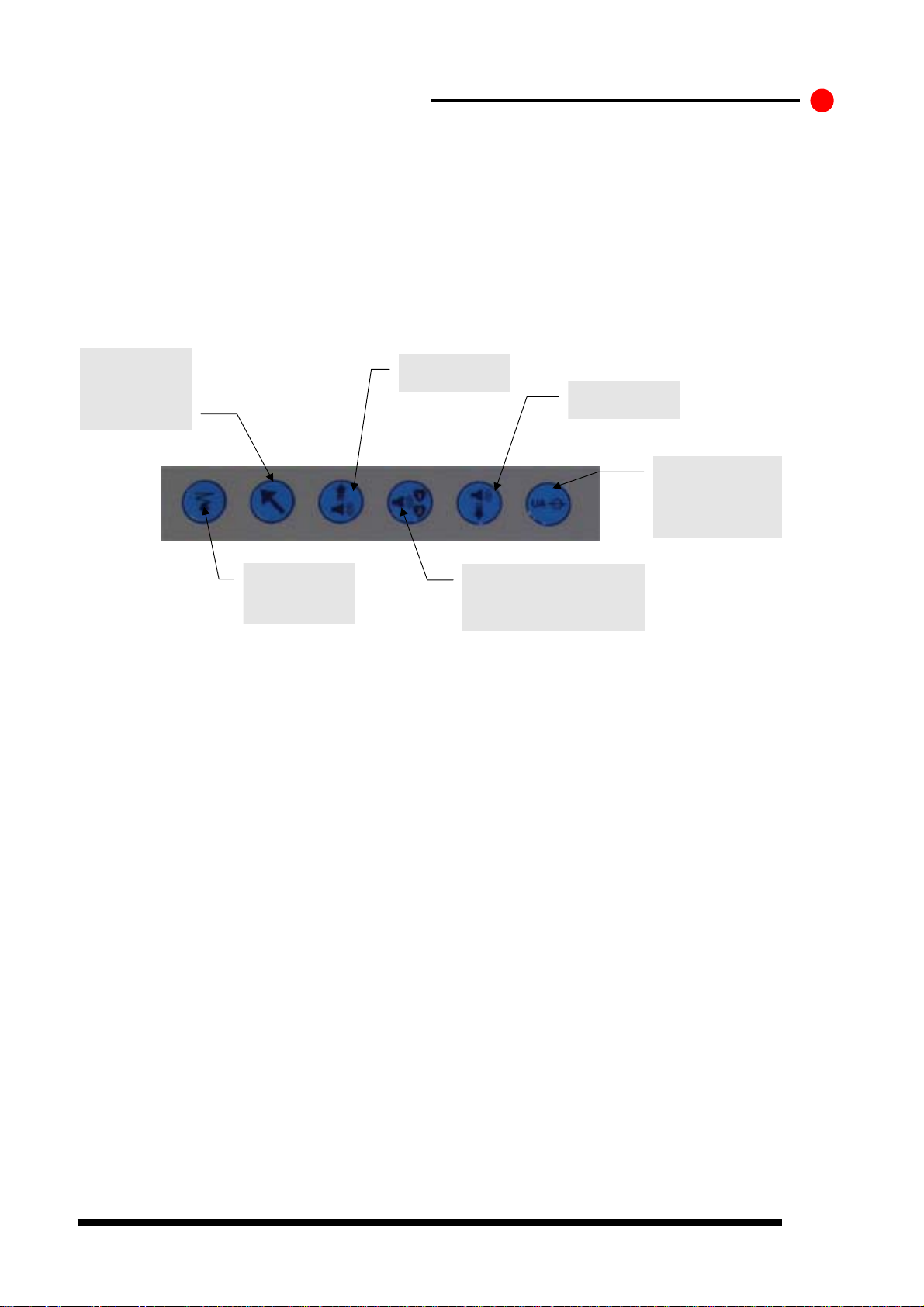
FETATRACK 310 front panel controls
The front p anel keyboard ar ea contains 6 keys used to co ntrol the operation of the unit, they
are all indic ated by Icons to aid language variations.
Event Mark 1.
Places arrow in
upper portion of
chart
Recorder On/Off and speed change
Event Mark 1
Volume Up
Volume Down
This key is used to decrease the audio volume level.
US1 / US2 Transducer Select
Toco Zero
Recorder On /
Off and speed
control
This key is used to control the operation of the recorder. Press once and the chart recorder will
start, each consecutive short press will change the speed . Press and hold the key will stop the
recording.
Places an event mark arrow at the top of the FHR scale .
This key is used to increase the audio volume level, or in configuration mode to change user
options.
Pressing this key changes the selected probe from US1 to US2 for volume output. This is used
when the unit is in Twins mode with two US channels for listening to either of the two fetus.
This key zeros the toco trace to the selected baseline.
Volume Up
Volume Down
Toco Zero.
Sets Toco channel
to preset baseline
value.
Select ultrasound channel
for audio output and twins
split trace.
©Ultrasound Technologies Ltd Issue 1 December 2004 Page 10
 Loading...