

UltraPlay UPLAY-015-P User Manual
uPLAY TODAY
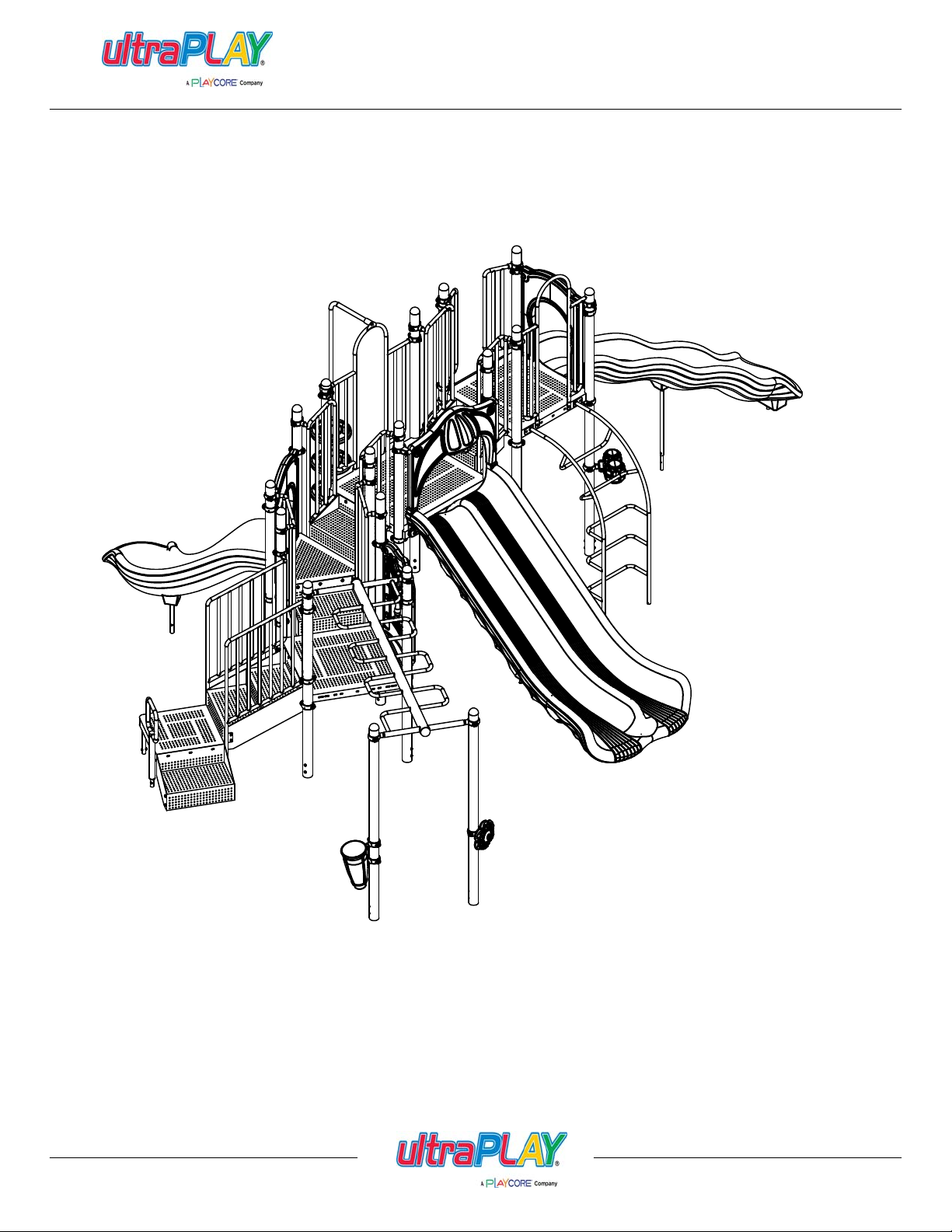
SLIDE MOUNTAIN
Issued/Revised:
800.458.5872
02/03/14
MODEL # UPLAY-015-N
MODEL # UPLAY-015-P
www.ultraplay.com


uPLAY TODAY
SLIDE MOUNTAIN
Dear UPlayToday™ Customer,
Thank you for choosing to purchase and in stall a UPlayToday commercial playsystem by UltraPlay®.
We appreciate the confidence you have placed in our company, and we will strive to earn your trust.
This is your Owner's Manual & Assembly Instructions booklet. We have designed this manual
specifically for the products that you have purchased. Included in this manual you will find the following:
-Maintenance schedule & record -Product installation instructions
-Safety guidelines -2D top view drawings
-Warranty information -Ground plan
Please save this booklet for future reference.
The first several pages of this booklet contain important and valuable information regarding the general
placement, installation and safety practi ces comm o n to commercial play equipment. Please read this
information carefully and use your best judgment as to how these guidelines apply to your specific
situation.
If you have any questions concerning your new equipment, you can contact a UPlayToday Customer
Service Representative at 1-800-458-5872 or reach them electronically by sending an e-mail
to: customerservice@ultraplay.com.
To register your equipment and activate your warranty, please go to www.ultraplay.com within 30
days of delivery. This will allow UltraPlay to have a record of your purchase in case of warranty
claims.
For more information on UPlayToday and UltraPlay products, please do not hesitate to give us a call or
visit ultraplay.com.
Thank you for your business; we look forward to working with you on all of your future playground
equipment projects!
Sincerely,
UPlayToday by UltraPlay
A PlayCore® Company
Issued/Revised:
02/03/14
800.458.5872
www.ultraplay.com
1

uPLAY TODAY
GENERAL COMMERCIAL PLAYGROUND SAFETY GUIDELINES
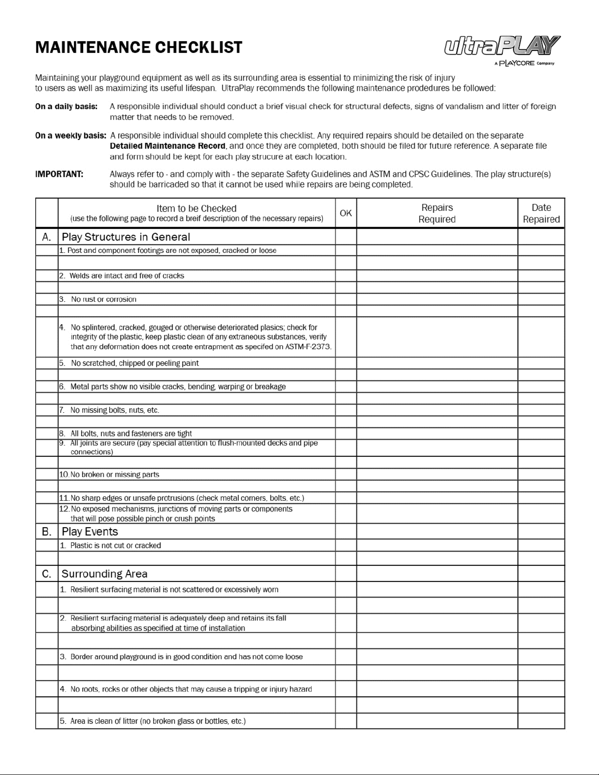
Maintaining your playgr ound equipment and its surrounding area is essential to minimizing the risk
of injury to users as well as maximizing its useful lifespan. UPlayToday STRON GLY recommends
that you follow these Safety Guidelines in conjunction with conducting periodic maintenance
inspections using the accompanying Playground Maintenance Checklist.
When installing your playground, always consider local conditions. Good common sense works
hand-in-hand with the instructions.
LOCATING YOUR PLAY STRUCTURE:
Comply with the following when choosing the location for your new equipment: Equipment
shall be positioned to eliminate conflicting traffic patterns. As a general rule, allow at least 72" of free
space around the entire structure, EXCEPT for slide exits, which require a distance X equal to the
highest point of the sliding surface with a minimum of 72" and maximum of 96" from the edge of the
slide. (example: a Wave Slide from a 72" deck requires 72" of clear space with resilient surfacing in
front of its exit.) Swings must have a minimum Use Zone in each direction of twice the swing beam
height. This minimum area should be filled with the appropriate resilient surface material. Read further
for resilient surfacing recommendations.
If your equipment includes any metal slides, t h ey should be positi oned in a shaded area, or at least
be placed to avoid the direct rays of the sun.
Never overlap the safety zones of adjacent equipment. All separate play equipment must have its
own safety zone, and these cannot overlap. So, if you have an existing structure with a slide exit
oriented toward your new one, add a minimum safety zone to that of the existing slide to determine
how far away you need to be. Never install playground equipment near, around, or in conjunction
with swimming pools, ponds, lakes, or any other bodies of water.
CHOOSING RESILIENT SURFACE MATERIAL:
NEVER INSTALL EQUIPMENT ON CONCRETE, ASPHALT OR EVEN GRASS WITHOUT
RESILIENT SURFACING! A fall on a hard surface from as low as a 36" high deck has been found
to result in serious injury to the user.
According to ASTM guidelines: "Unacceptable material for use zones of play structures with fall
heights of 18" or less shall include all hard or abrasive materials such as asphalt, concrete,
terrazzo, or other materials with similar characteristics. "Other standards apply for equipment with
fall heights greater than 18".
Soft, resilient surfacing should be placed in the use zones of all equipment, as specified for each
type of equipment, and at depths to meet the critical fall heights as specified by the U.S. Consumer
Product Safety Commissi o n , ASTM standard F-1487 and Canadian Standard CAN/CSA-Z-614.
Your UPlayToday structure has a maximum fall height of 72".
Issued/Revised:
800.458.5872
02/03/14
www.ultraplay.com
2

uPLAY TODAY
GENERAL COMMERCIAL PLAYGROUND SAFETY GUIDELINES
Install Wood Mulch (EWF) at a depth of 12". Over time this mulch will compress to a depth of 9"
as required by the U.S. Consumer Product Safery Commission, ASTM standard F-1487 and
Canadian Standard CAN/CSA-Z-614. For more information on the proper surfacing materials, call
the CPSC hotline at 1-800-638-2772.
Worn surfaces around equipment should be restored. Concrete footings should never be exposed.
Refer to the attached PLAYGROUND MAINTENANCE CHECKLIST.
Check for erosion and cratering of surfaces under slides and heavy traffic areas and restore
surfacing as necessary.
Surfacing leading to play opportunities for children with disabilities should be firm, stable, slip
resistant, and resilient.
Tip: If your surfacing is of the loose variety, checking for proper depth over time can be made easy
by applying a non-removable fluorescent tape of paint in a bright color at the proper level on each
upright post. Thereafter, as the resilient material compacts or washes away, the person re sponsible
for regular maintenance inspections can easily see it must be replenished as the marks become
visible.
OVERHEAD OBSTRUCTIONS:
Overhead obstructions (for example, exterior obstructions such as tree limbs and interior lights)
within the use zones of play structures shall be a minimum 84" (2130 mm) above each designated
play surface outdoors and a minimum of 48" (1220 mm) above each designated play surface
indoors.
All overhead utility line clearances above outdoor supervised and outdoor unlimited access settings
shall comply with all local, state, and national codes, such as the National Electrical Safety Code.
For specific equipment fall zone requirements, refer to the CPSC and ASTM F1487 and use the
more stringent of the two.
CATCH POINT & PROTRUDING HARDWARE:
There should be no dangerous pieces of hardware, such as protruding bolt ends and narrow gaps in
metal connections. Exposed hardware can cut or puncture skin and catch clothing drawstrings,
which could strangle a child.
All protruding nuts and bolts should be eliminated; sharp edges on pipes should be capped or
removed. Check for bent, broken, or severely worn pipe and replace. Examine slide bedways,
bedrails, handrails and exits for foreign objects, holes, and rough edges.
Issued/Revised:
800.458.5872
02/03/14
www.ultraplay.com
3

uPLAY TODAY
GENERAL COMMERCIAL PLAYGROUND SAFETY GUIDELINES
TRIPPING HAZARDS:
There should be no expo sed concrete footings, abrupt changes in surface elevations, tree roots, tree
stumps, and rocks, which can trip children and adults. Check for trip hazards, such as the balance
beam support posts, or environmental trip hazards, such as rocks or roots in the play area. Make all
necessary improvements or repairs.
AFTER THE EQUIPMENT IS IN USE:
-Never add components not intended for use with this product.
-Never install other play equipment, fencing, landscaping, etc., that encroach upon the sa fety
zones of this equipment.
-Check overall stability and rigidity of all play equipment.
-Check for proper assembly, installation and ground anchoring.
-Check and re-tighten all fasteners after the first few days of use and again after three weeks of use.
Thereafter, exercise normal maintenance procedures. Use of a thread-locking compound on the
threads of bolts can prevent persistent loosening.
ROUTINE MAINTENANCE:
Regularly inspect and maintain your playground equipment and its surrounding area to help ensure
the safety of the user. Proper maintenance of UPlayToday equipment includes using the
accompanying Playground Maintenance Checklist found in this booklet to identify areas requiring
repairs or replacement, and barricading the equipment to prevent use while corrections are being
made.
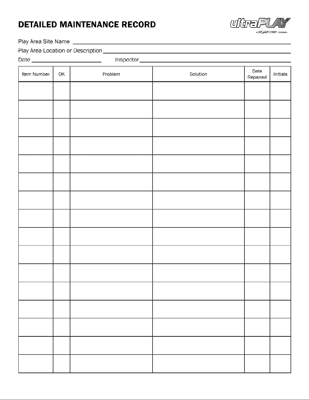
As the Owner/Operator of the equipment, you should establish and maintain detailed installation,
inspection, maintenance, and repair records for each public-use playground equipment area. Find
out if your playground has a designated official who periodically inspects the play equipment for
preventative maintenance. This includes but is not limited to: replacing missing, broken or worn-out
components; securing hardware; checking for deterioration in the metal or plastic materials;
maintaining the proper depth of surfacing material; and cleaning up debris.
The following are some regular maintenance areas of note:
-Check for and repair damage caused by wear or vandalism, a major factor in injury causing
situations.
Continued on next page
Issued/Revised:
800.458.5872
02/03/14
www.ultraplay.com
4

uPLAY TODAY
GENERAL COMMERCIAL PLAYGROUND SAFETY GUIDELINES
-Proper maintenance of UPlayToday equipment requires regular tightening of all bolts, nuts, set
screws, and other hardware.
-All equipment should be free of rust and repainted with an appropriate lead-free paint whenever
necessary to deter rusting. This should also be done for any chipped or peeling areas.
-Regular checking of all parts, casting, etc., should be made. If part is broken or worn it should be
replaced immediately.
-Check for missing or broken parts, rungs, or steps and repair as necessary.
-Check to be sure there is free movement on moving attached parts.
-Check for hard surfaces and correct, including under slides and etc. where loose surfacing may
have been kicked away. Refer to CPSC surfacing requirements.
-Check for surfacing material that is worn or scattered and restore.
-Debris, broken glass, trash, or other foreign objects within or on the play area/equipment should be
removed.
-Check for poor drainage areas and re pair.
-Check concrete footings to see if they are exposed, cracked, or loose in the ground and repair as
necessary.
-Check for crush points (exposed mechanisms, juncture s of moving components) and eliminate.
-Check for broken supports or anchors. Check for stability in ground. Structures should not be
easily swayed; connections should be solid and adequately secured.
-Check all posts in ground for corrosion or rot below grade.
-When flexible components are anchored in the ground, check and make sure anchoring devices
are below the level of the playground.
-Check exit areas of slides. The exit area should be no more than 11" from the protective surface for
slides under 48" high. For slides over 48" high, the height of the exit regi on from the surface
should be between 7" and 15".
-Check the surface area around slide exit for erosion and other damage and repair if necessary.
-Check for visible cracks, bending, warping, rusting, or breakage of any component and repair as
needed.
Issued/Revised:
800.458.5872
02/03/14
www.ultraplay.com
5

uPLAY TODAY
GENERAL COMMERCIAL PLAYGROUND SAFETY GUIDELINES
-Check for accessible sharp edges or points. Check for protruding bars, bolts, nuts, etc. Eliminate
these conditions.
-Check for exposed ends of tubing that should be covered with plugs or caps.
-Check for loose bolts, nuts, etc. and tighten.
-Check for broken or missing rails, steps, rungs, or seats and replace.
Issued/Revised:
800.458.5872
02/03/14
www.ultraplay.com
6

uPLAY TODAY
UPlayToday Warranty
UltraPlay warrants its products to be free from defects in materials and/or workmanship, subject to
normal usage and installation, for a period of 1-year from the date of shipment to the original
purchaser. In the event of a claim under this wa rranty, UltraPlay will replace the component at no
cost within the first 12 months from date of shipment to the original customer. Equipment not
specifically addressed in the following paragraphs is also subject to this limited 1 year warranty
against defects in materials and/or workmanship.
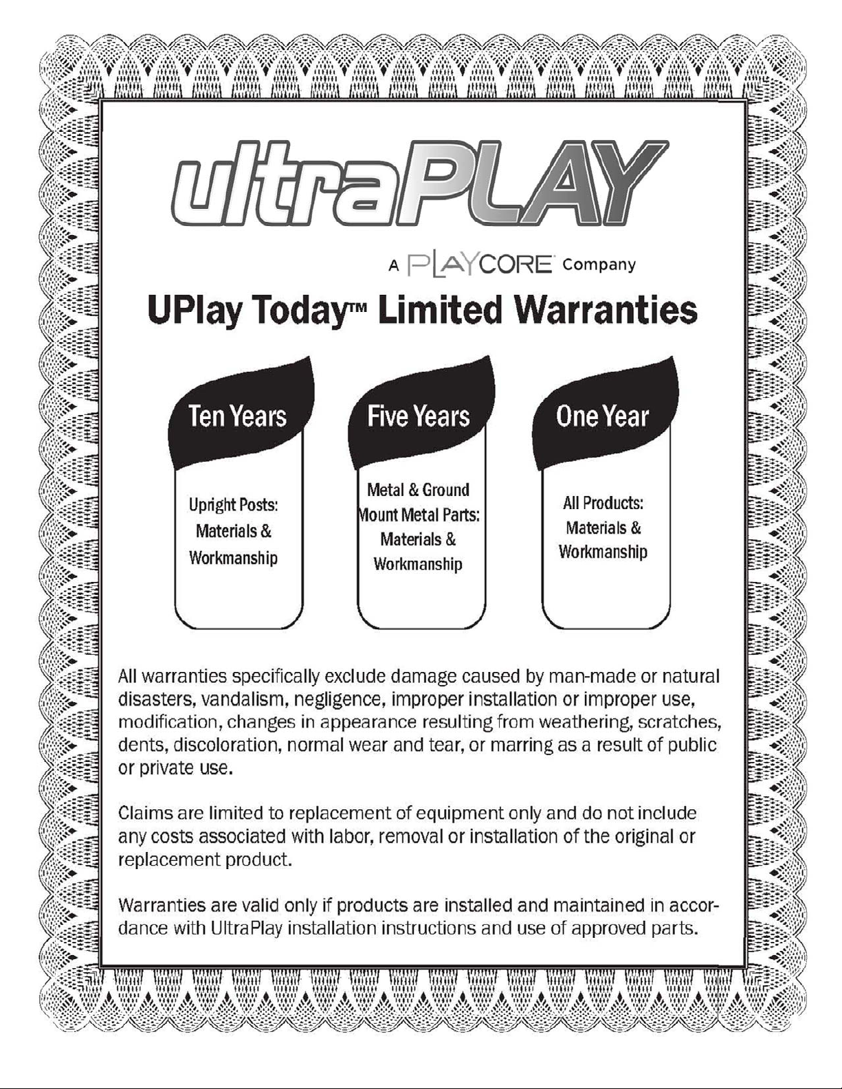
TEN-YEAR LIMITED WARRANTY ON UPRIGHT POSTS
UltraPlay provides a limited warranty on metal upright posts to be free from defects in materials or
workmanship against structural failure which causes the product to become unfit for its intended use,
subject to normal usage and installation, for a period of 10 years from the date of shipment to the
original customer.
FIVE-YEAR LIMITED WARRANTY ON METAL PARTS
UltraPlay provides a limited warranty on metal decks, steps, stairs, rails, pipes, support posts, rungs,
loops, and clamps to be free from defects in materials or workmanship against structural failure
which causes the product to become unfit for its intended use, subject to normal usage and
installation, for a period of 5 years from the date of shipment to the original customer.
FIVE-YEAR LIMITED WARRANTY ON GROUND-MOUNT METAL PARTS
UltraPlay provides a limited warranty on metal footers, inground footers, surface mount plates,
ground spikes, slide and climber mounting posts and plates to be free from defects in materials or
workmanship against structural failure which causes the product to become unfit for its intended use,
subject to normal usage and installation, for a period of 5 years from the date of shipment to the
original customer.
THREE-YEAR LIMITED WARRANTY ON PLASTIC PARTS
UltraPlay provides a limited warranty on the following plastic parts: slides, climbers, roofs, tunnels,
bridges, panels, and border timbers. These components are warranted to be free from defects in
material or workmanship, subject to normal usage and installation, for a period of 3 years from the
date of shipment to the original customer.
ONE-YEAR LIMITED WARRANTY ON HARDWARE
UltraPlay Systems provides a limited warranty on hardware to be free from defects in materials or
workmanship against structural failure due to breaking or shearing, subject to normal usage and
installation, for a period of 1 year from the date of shipment to the original customer.
ONE-YEAR LIMITED WARRANTY ON HDPE CLIMBER
UltraPlay provides a limited warranty on high density polyethylene (HDPE) climber against
degradation for a peri od of 1 year from the date of shipment to the original customer.
Issued/Revised:
800.458.5872
02/03/14
www.ultraplay.com
10

uPLAY TODAY
WARRANTY EXCLUSIONS
All warranties specifically exclude damage caused by man-made or natural disasters, vandalism,
negligence, improper installation or improper use, modification, changes in appearance resulting
from weathering, scratches, dents, discoloration, normal wear and tear, or marring as a result of
public or private use.
Claims are limited to replacement of equipment only and do not include any costs associated with
labor, removal, or inst allation of the original or replacement product.
Warranties are valid only if products are installed and maintained in accordance with UltraPlay
installation instructions and use of approved parts.
This warranty is applicable to the original owner only. Warranties are non-transferable.
Claim Procedure: To make a warranty claim, send your written statement of claim, photographs of
defective equipment, and the original purchase invoice or invoice number to:
UPlayToday
Customer Service
1675 Locust Street
Red Bud, IL 62278
Or Contact a Customer Service Representative at: 1-800-458-5872
Within 60 days of notice of claim under warranty, UltraPlay will make arrangements to replace the
damaged product. UltraPlay will cover freight costs within the continental United States. UltraPlay is
not responsible for freight costs associated with products located outside the continental United
States. UltraPlay reserves the right to inspect all products identified as defective. Photos of defective
equipment may be required to accompany warranty claims.
Since warranty limitations and exclusions may vary from state to state, you should check any specific
warranty rights in your state.
Date of Purchase:_______________________
Purchaser:_____________________________
UltraPlay Invoice Number:________________
____________________________________
Authorized UltraPlay Signature
____________________________________
Title
Visit UltraPlay on the web at www.ultraplay.com
Issued/Revised:
800.458.5872
02/03/14
www.ultraplay.com
11

uPLAY TODAY
GENERAL INTRODUCTION TO INSTALLATION INSTRUCTIONS
IMPORTANT! Please read the entire Installation Instructions packet before beginning the
installation.
UltraPlay has designed UPlayToday to take advantage of all Consumer Product Safety Commission
(CPSC) and ASTM guidelines in force at the time of purchase in an effort to prevent playground
accidents. However, because studies have shown most playground injuries result from accidental
falls, you, as the new owner of this equipment are responsible for providing an acceptable play
surface under and around all playground equipment. Please refer to the accompanying Safety
Guidelines as well as CPSC guidelines and this document for examples of such surfacing.
We would like to provide the following suggested guidelines for your play environment:
-Refer to the Use Zone and note the Minimum Area required shown for this structure. This area
must be filled with acceptable play surface material, and must be clear of all obstacles, including but
not limited to trees, curbing, sidewalk, fence, other play equipment, rocks, and landscaping, etc.
-According to ASTM guidelines: "Unacceptable materials for use zones of play structures with fall
heights of 18" or less shall include all hard or abrasive materials such as asphalt, concrete,
terrazzo, or other materials with similar characteristics." Other standards apply for equipment with
fall heights greater than 18".
-Acceptable play surfaces include: sand, mulch, fine gravel or shredded belt-less tires, if installed at
the appropriate depths per CPSC guidelines for play surfacing.
-When using sand, mulch, or shredded belt-less tires, a minimum of 6" depth is recommended by
the CPSC. UPlayToday recommends an additional 6", for a total of 12", to combat the fast
compacting characteristics of these materials. Surfaces must be checked at least weekly for
compacting, which reduces resiliency significantly.
-Surfaces such as asphalt, concrete, gravel, or sod are not acceptable for use under playground
equipment, or anywhere within the stated Use Zone.
-Unitary resilient surfacing designed for playground use, including rubber tiles, poured-in-place
rubber surfacing, bonded rubber surfacing, and synthetic playground turf is also recommended.
-Close supervision of children playing on or around the structure is strongl y recommended, along
with classroom and/or home instructions on safer behavior on the playground equipment. The full
supervision of playgrounds is the responsibility of the owner once the play structure has been
properly installed.
Continue on next page
Issued/Revised:
800.458.5872
02/03/14
www.ultraplay.com
12

uPLAY TODAY
GENERAL INTRODUCTION TO INSTALLATION INSTRUCTIONS
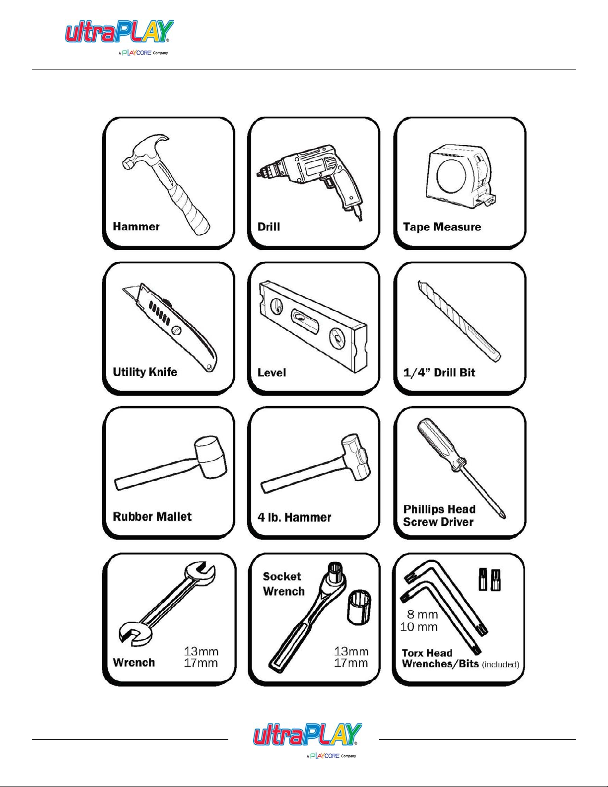
TOOLS REQUIRED:
UltraPlay supplies only the special wrenches and bits required to fasten the "tamper-resi stant "
hardware and components. You will need common wrenches and an Allen key set as well as a drill,
string line, level, shovels, post hole digger, pry bar, washable felt tip marker, phillips head screw
driver, utility knife, rubber mallet, and a tape measure. A power post hole digger may facilitate
installation in some circumstances. Refer to the Tools Required page for a detailed list.
INSTALLATION GUIDELINES:
1. Compare all parts received to the packing list. Notify UltraPlay immediately of any missing parts.
We are not responsible for parts discovered missing over 10 days after receipt of the shipment.
2. Refer to the Use Zone to ensure this structure will fit into your actual site area. Note the Minimum
Area Required measurements to determine clear space required. A minimum of 72" clearance is
required between any obstacles and your structure. EXCEPT for slide exits, which require a
distiance X equal to the highest point of sliding surface with a minimum of 72" and a maximum of
96" from the edge of the slide (example: A Wave Slide from a 72" high deck requires 72" of clear
space with resilient surfacing in front of its exit).
3. Site selection should incl ude considerations of what is a safe and appropriate play area:
-A level and clear site is ideal, free of power lines or electrical equipment.
-Do not install play equipment near any bodies of water.
-If adjacent to a street with traffic, ensure adequate fencing acts as a barrier to children running
into danger.
4. Site layout should include accurate measurement and marking of all footings prior to any
installation. Use the dimensions shown between footings on the Use Zone to plot out the actual
footprint of the play structure before doing any digging. Also locate any freestanding play
equipment in the same way, providing the necessary clearance between the equipment as well as
any fences, trees, etc. Ensure at this time you have enough total space for the equipment to be
installed.
5. If using inground footers, excavate holes as shown in the Use Zone using a string line. An optional
string line level is very helpful. If a level and clear site is not possible, adjust the depth of the
footings to maintain a minimum depth of 18" for support posts at the lowest grade. NOTE: If soil
conditions are very loose or otherwise unstable, a larger diameter footing may be required. Inquire
with local contractors for appropriate recommendations.
6. Begin your UPlayToday installation by erecting the decks as shown within the following instructions.
Once all decks are installed, components such as slides, climbers, etc., can be connected per their
respective assembly instructions. Note that connecting components between decks such as Crawl
Tunnels and Bone Bridges should be installed concurrently with the decks to ensure they are
accurate.
Issued/Revised:
800.458.5872
02/03/14
www.ultraplay.com
13

uPLAY TODAY
GENERAL INTRODUCTION TO INSTALLATION INSTRUCTIONS
7. CPSC guidelines mandate that there shall be no gaps present in the playground equipment that
fall between 3-1/2" and 9". The positioning of certain components by the installer can affect this
criteria, so you should always measure distances created when attaching components in order to
avoid these spaces which can cause entrapment of a child using the equipment. Also, ASTM
requires that no more than 2 threads of a bolt can protrude from the nut. Any excess threads
should be filed down and made smooth to the touch.
8. When concrete is poured, be sure to keep the top 4" below grade, and sloped away from the post
to promote good water drainage. Wash off any concrete that may have splashed onto the post
before it dries. Allow all concrete to harden a minimum of 48 hours before allowing use.
SAFETY DURING INSTALLATION:
1. Before doing any excavation, inquire about any existing underground utilities.
2. Do not leave the job site unattended without making sure that all fastening hardware on all
equipment is tightened and all drive rivets are in place to prevent clamps from moving, in case
of unauthorized use. UPlayToday CLAMPS ARE NOT DESIGNED TO SUPPORT HUMAN
WEIGHT WITHOUT THE DRIVE RIVETS INSTALLED, AND SUCH USE COULD CAUSE
INJURY TO THE USER AND/OR DAMAGE TO THE EQUIPMENT. It is also strongly
recommended that all installation areas be roped off with clearly marked warning signs posted.
Any open footings should be covered with plywood or other suitable material. Even during
installation, it has been found that children will use the unattended equipment, thereby risking
accidents.
3. If concrete footings and inground footers are being used, it is strongly recommended that the
installation area should remain roped off for at least 48 hours after the last concrete footing is
poured. Children should not be allowed to use the equipment during this period so that concrete
has a chance to fully cure.
Finally, if you should have any questions regarding the proper installation of this equipment, please
contact UltraPlay at:
UPlayToday Customer Service
1675 Locust Street, Red Bud, IL 62278
1-800-458-5872 Fax 1-618-282-8202
Email: customerservice@uplaytoday.com
Issued/Revised:
800.458.5872
02/03/14
www.ultraplay.com
14

uPLAY TODAY
WARNING LABEL APPLICATION INSTRUCTIONS
The enclosed Warning Labels must be affixed to your playground equipment. At least one Warning
Label is needed per play structure, permanently affixed in a conspicuous location within easy view
of users.
INSTRUCTIONS:
1. Fully assemble and install your UPlayToday playground equipment per the accompying
installatioin instructions.
2. When installation of the equipment is complete, and prior to allowing use of the equipment, identify
a suitable location on the structure to receive the Warning Label. An upright post is recommended,
approximately 48" above the ground. Choose an upright post most likely to be seen by the user
immediately upon entry into the play area.
3. Fully clean the surface to receive the label with soap and water, and ensure that no oils, film, or dirt
remain.
4. Allow surface to dry fully. Apply the Warning Label, smoothing over the surface with a clean cloth
so there are no air bubbles present.
5. For larger structures (more than 16 upright posts), use 2 labels, positioning one at each end of the
structure. Always choose locations, which are likely to be seen by users prior to use of the
equipment, preferably near the entry point of the play area.
ALWAYS FOLLOW THE RECOMMENDATIONS CONTAINED IN THE ACCOMPANYING SAFETY
GUIDELINES REGARDING THE INSTALLATION AND MAINTENANCE OF APPROPRIATE
RESILIENT SURFACE MATERIALS REQUIRED FOR YOUR PLAY AREA. NEVER ALLOW USE
OF PLAYGROUND EQUIPMENT WITHOUT PROPER SAFETY SURFACING AS FALLS ONTO A
HARD SURFACE CAN CAUSE SERIOUS INJURY TO THE USER.
Issued/Revised:
800.458.5872
02/03/14
www.ultraplay.com
15
uPLAY TODAY
TOOLS REQUIRED
Issued/Revised:
800.458.5872
02/03/14
www.ultraplay.com
16
INCH0
1
2
365
4
0
CM
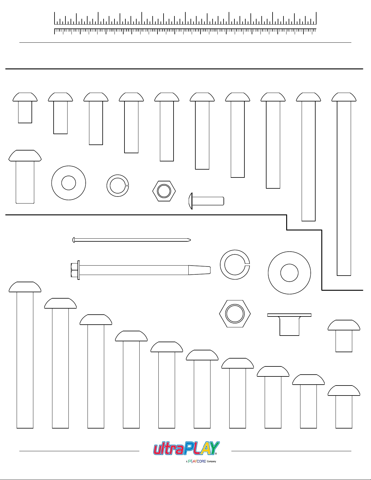
M8 B.H.C.S. Bolts
13mm
1/2"
(33-11-0101)
M8 Barrel Nut
(33-11-0501)
20mm
3/4"
(33-11-0102)
M8 Flat Washer
(33-11-0300)
1
(33-11-0103)
2
3
HARDWARE REFERENCE
25mm
1"
M8 Lock Washer
(33-11-0301)
5
4
30mm
1-3/16"
(33-11-0104)
7
35mm
1 3/8"
(33-11-0105)
M8 Lock Nut
(33-11-0500)
40mm
1-9/16"
(33-11-0106)
Clamp Rivet
(33-11-0700)
10961114815
45mm
1-3/4"
(33-11-0109)
12 13
50mm
2"
(33-11-0114)
70mm
2-3/4"
(33-11-0107)
100mm
4"
(33-11-0113)
M10 B.H.C.S. Bolts
80mm
3-1/8"
(33-11-0011)
70mm
2-3/4"
(33-11-0008)
18" Ground Spike (Not to Scale)
(02-08-0048)
M5 x 76mm (3") Self-Tapping Screw
(33-11-0600)
60mm
2-3/8"
(33-11-0007)
50mm
2"
(33-11-0010)
(33-11-0013)
45mm
1-3/4"
M10 Lock Washer
40mm
1-9/16"
(33-11-0006)
(33-11-0201)
M10 Lock Nut
(33-11-0400)
35mm
1-3/8"
(33-11-0005)
M10 Flat Washer
(33-11-0200)
M10 T-Nut
(33-11-0402)
30mm
1-3/16"
(33-11-0004)
25mm
1"
(33-11-0003)
13mm
1/2"
(33-11-0001)
20mm
3/4"
(33-11-0002)
Issued/Revised:
800.458.5872
02/03/14
www.ultraplay.com
17
uPLAY TODAY
UPRIGHT PLACEMENT
UPRIGHTS LIST
QTYDESCRIPTION
6'-11" UPRIGHT
7'-6" UPRIGHT
7'-8" UPRIGHT
8'-4" UPRIGHT
8'-8" UPRIGHT
9'-6" UPRIGHT
PART NUMBER
02-07-50742
02-07-50752
02-07-50251
02-07-50262
02-07-50762
02-07-507729'-5" UPRIGHT
02-07-50272
02-07-507829'-8" UPRIGHT
9'-8" UPRIGHT
(02-07-5078)
9'-6" UPRIGHT
(02-07-5027)
8'-8" UPRIGHT
(02-07-5076)
9'-5" UPRIGHT
(02-07-5077)
7'-6" UPRIGHT
(02-07-5075)
6'-11" UPRIGHT
(02-07-5074)
7'-8" UPRIGHT
(02-07-5025)
8'-4" UPRIGHT
(02-07-5026)
Issued/Revised:
800.458.5872
02/03/14
www.ultraplay.com
18
37'-0"
5FT DOUBLE STRAIGHT
SLIDE (02-07-5065)
6FT RUNG CLIMBER
(02-07-5019)
BONGO DRUMS
(02-07-5024)
6FT WAVE SLIDE
(02-07-5006)
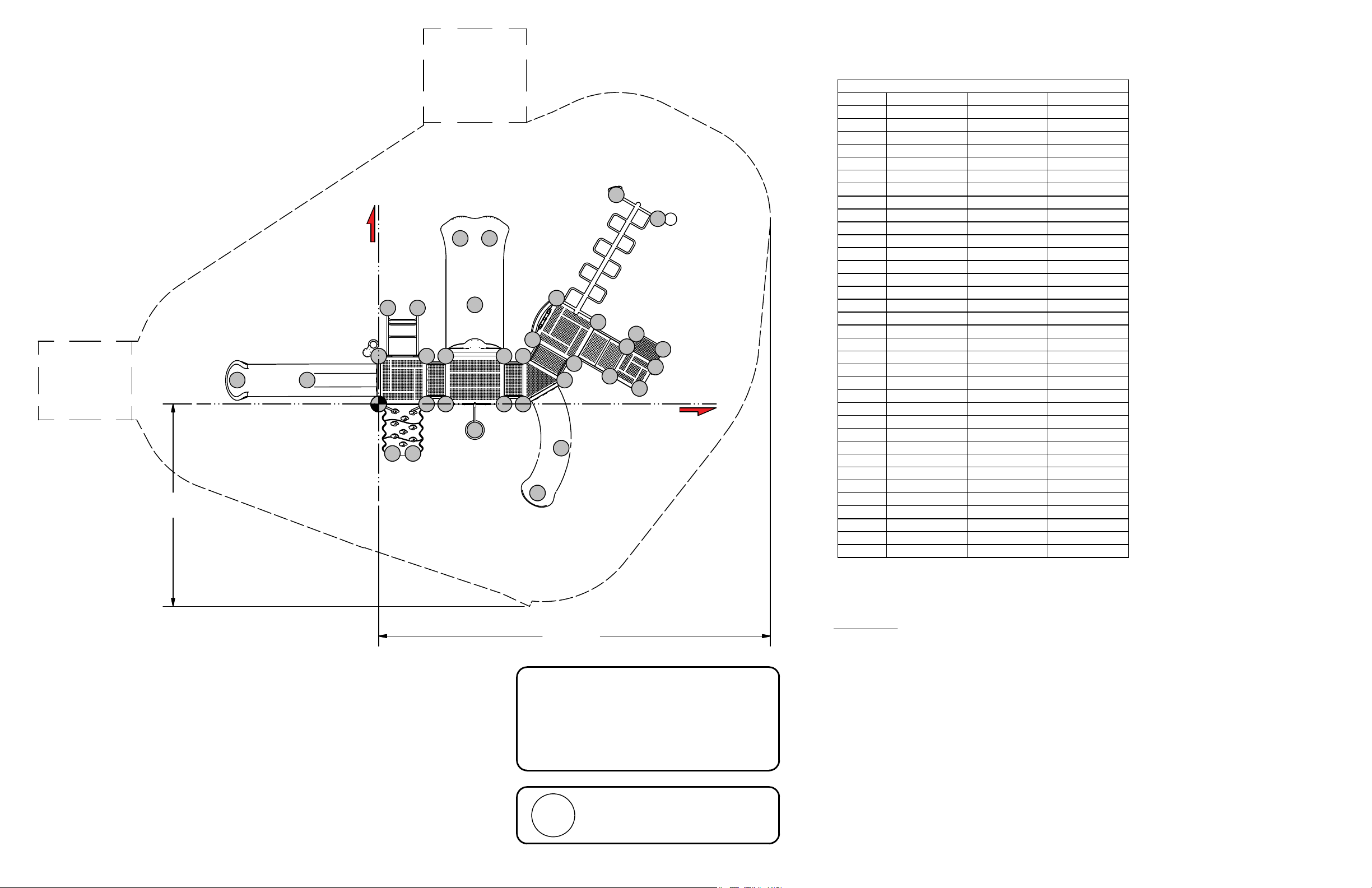
uPLAY TODAY
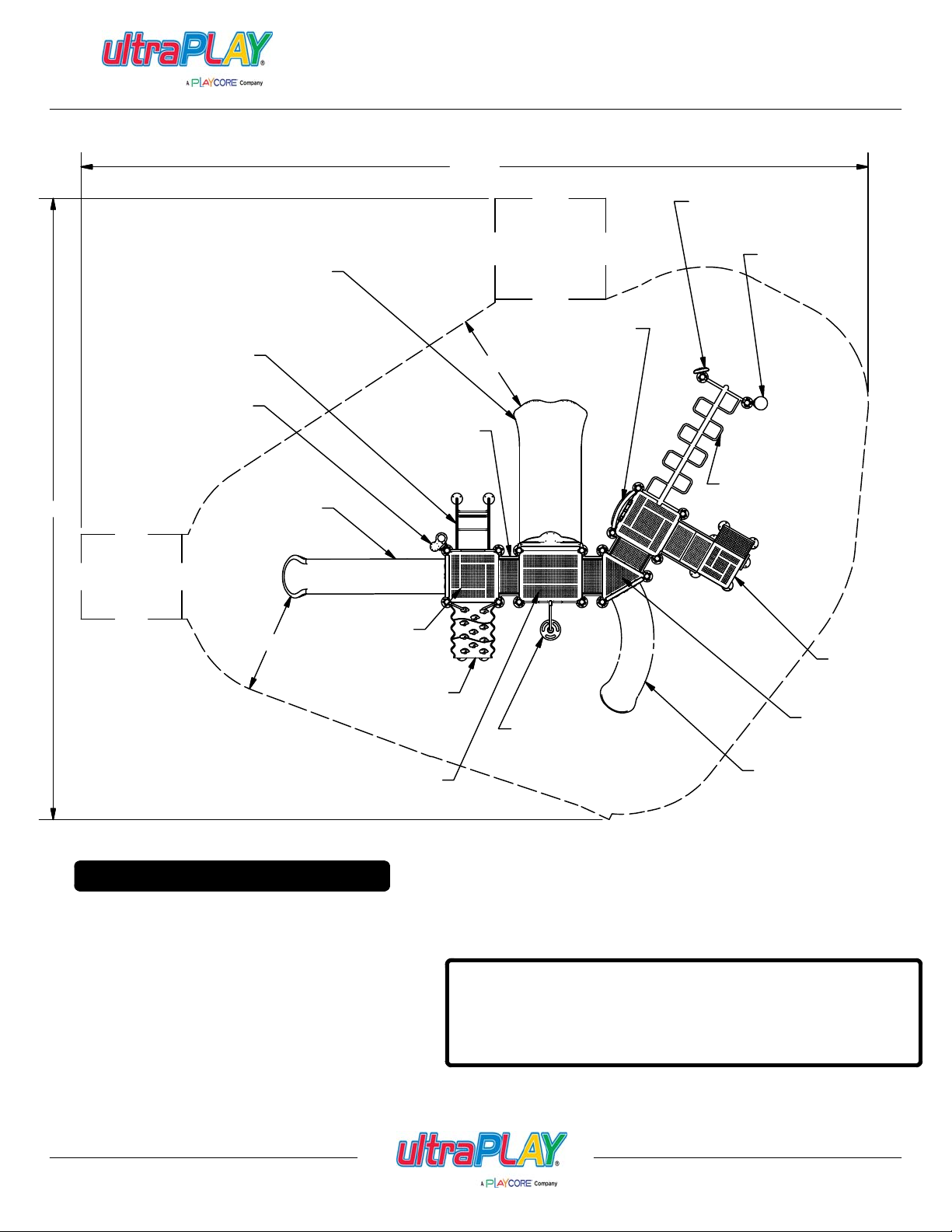
USE ZONE
46'-11"
RAINWHEEL
(02-07-5022)
BASS DRUM
(02-07-5023)
SHIP'S WHEEL PANEL
(02-07-5012)
6'-0"
1FT STAIRS
(02-07-5064)
OVERHEAD LADDER
(02-07-5042)
6'-0"
SQUARE DECK
(02-07-5001)
HDPE CLIMBER
(02-07-5018)
RECTANGLE DECK
(02-07-5038)
MINIMUM USE ZONE* REQUIRED
*The USE ZONE is the area beneath
and immediately adjacent to a play
structure or equipment that is designed
for unrestricted circulation around the
equipment and on whose surface it is
predicted that a user would land when
falling from or exiting the equipment.
3FT ADA STEPS
(02-07-5039)
5FT BEANSTALK
CLIMBER -WIDE(02-07-5060)
NOTE:
Equipment shall be positioned to eliminate conflicting traffic
patterns. As a general rule, allow at least 3' of freespace
around the entire structure.
IMPORTANT: Never install play equipment over hard, unresilient
surfaces such as asphalt, concrete, or compacted earth. It is the
owner's responsibility to ensure the "minimum area required"
contains an appropriate amount of resilient materal to cushion
accidental falls.
4FT RIGHT CURVED SLIDE
(02-07-5005)
TRIANGLE DECK
(02-07-5037)
Issued/Revised:
800.458.5872
02/03/14
www.ultraplay.com
19
uPLAY TODAY
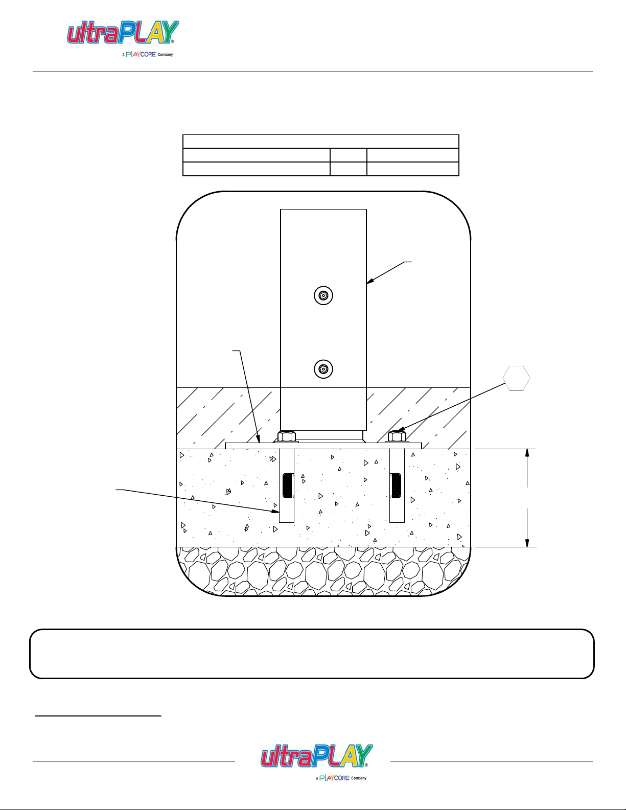
FOOTING DETAIL - SURFACE MOUNT
(33-12-0105)
Parts List
QTYDESCRIPTION
PART NUMBER
33-11-0702105CONCRETE ANCHOR
UPRIGHT
POST
UPRIGHT
FOOTER
067
CONCRETE
ANCHOR
CONCRETE
4" MINIMUM
w/3000 PSI
GRAVEL
IMPORTANT: Never install play equipment over hard, unresilient surfaces such as asphalt, concrete,
or compacted earth. It is the owner's responsibility to ensure the "mi nim um ar ea required" contains an
appropriate amoun t of resilient material to cushion accidental falls.
SITE PREPARATION
Clear area of any debris and level surface. Equipment is designed to be installed on a level surface.
Issued/Revised:
800.458.5872
02/03/14
www.ultraplay.com
20
INCH0
1
2
365
4
5
1
0
CM
2
4
3
7
10961114815
12 13
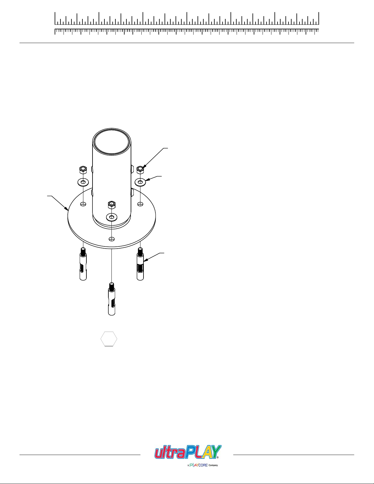
FOOTING DETAIL - SURFACE MOUNT
1. Using Upright Footers as template, mark hole position on concrete. Drill 3/8" Dia. x 2" deep holes into concrete to receive anchor.
2. Attach Upright Footers to concrete using Concrete Anchor, Flat Washer, and Lock Nut. See Detail 067.
LOCK NUT
FLAT WASHER
UPRIGHT
FOOTER
067
CONCRETE
ANCHOR
Issued/Revised:
800.458.5872
02/03/14
www.ultraplay.com
21
IMPORTANT:
UPRIGHTS WILL COME
PRE-ASSEMBLED WITH
UPRIGHT FOOTER
POSITIONED IN THE
BOTTOM (2) HOLES TO
ACCOMODATE 2" OF
SURFACING. WHEN
INSTALLING 12" OF
SURFACING, REMOVE
BOLTS AND ADJUST
UPRIGHT FOOTER
POSITION TO UTILIZE
THE TOP (2) HOLES.
068
uPLAY TODAY
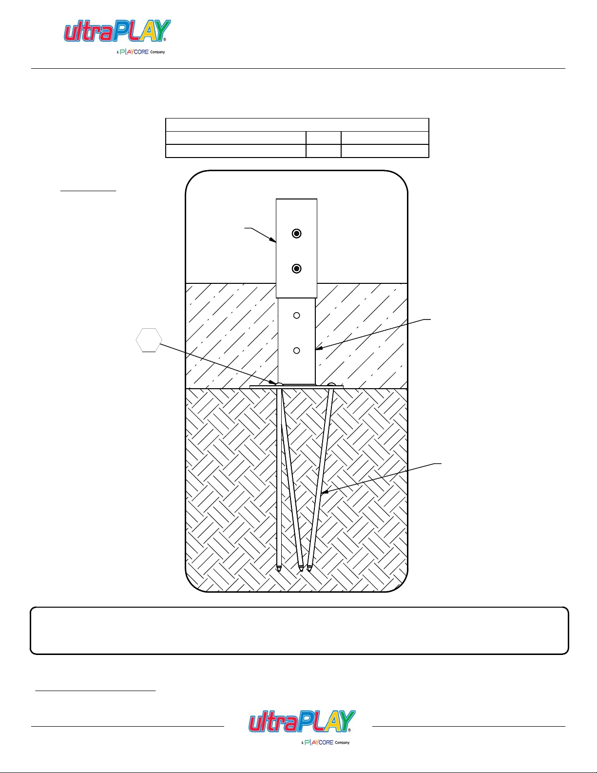
FOOTING DETAIL - ON GROUND
(33-12-0124)
Parts List
QTYDESCRIPTION
UPRIGHT
POST
SURFACING
PART NUMBER
02-07-0048105GROUND SPIKE
UPRIGHT
FOOTER
GROUND
SPIKE
GROUND
IMPORTANT: Never install play equipment over hard, unresilient surfaces such as asphalt, concrete,
or compacted earth. It is the owner's responsibility to ensure the "minimum area required" contains an
appropriate amount of resilient material to cushion accidental falls.
SITE PREPARATION
Clear area of any debris and level surface. Equipment is designed to be installed on a level surface.
Issued/Revised:
02/03/14
800.458.5872
www.ultraplay.com
22
INCH0
1
2
365
4
5
1
0
CM
2
4
3
7
10961114815
12 13
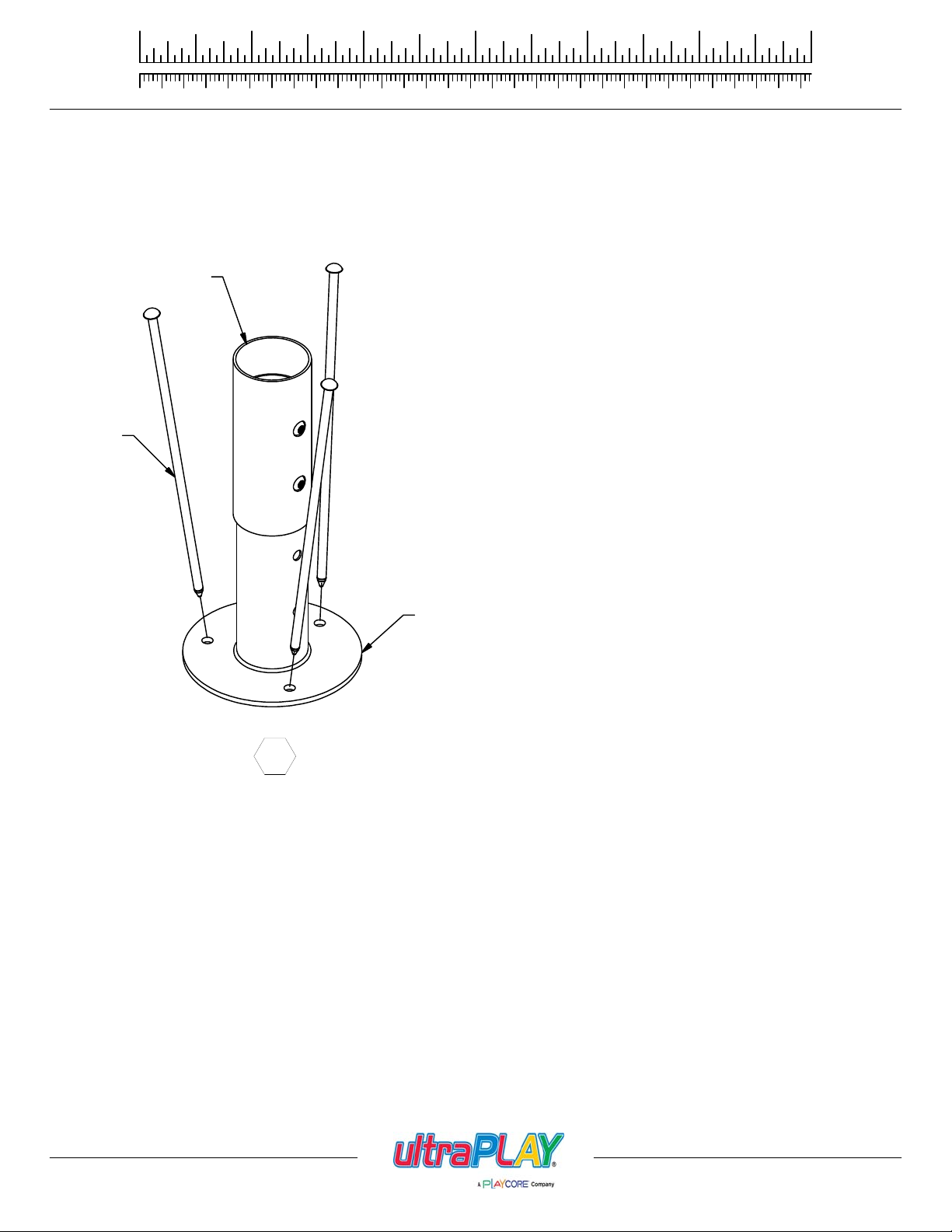
FOOTING DETAIL - ON GROUND
1. With Upright Footers in position, secure each Upright Footer to the ground using Ground Spikes. NOTE: A 4lb. hammer may be required
to drive spikes into the ground. Install ground spikes angled inward as shown in illustration. See Detail 068. IMPORTANT: Refer to
Post Placement/Hole Locations diagram to mark locations of Upright Footers.
UPRIGHT
GROUND
SPIKE
068
UPRIGHT
FOOTER
Issued/Revised:
800.458.5872
02/03/14
www.ultraplay.com
23
uPLAY TODAY
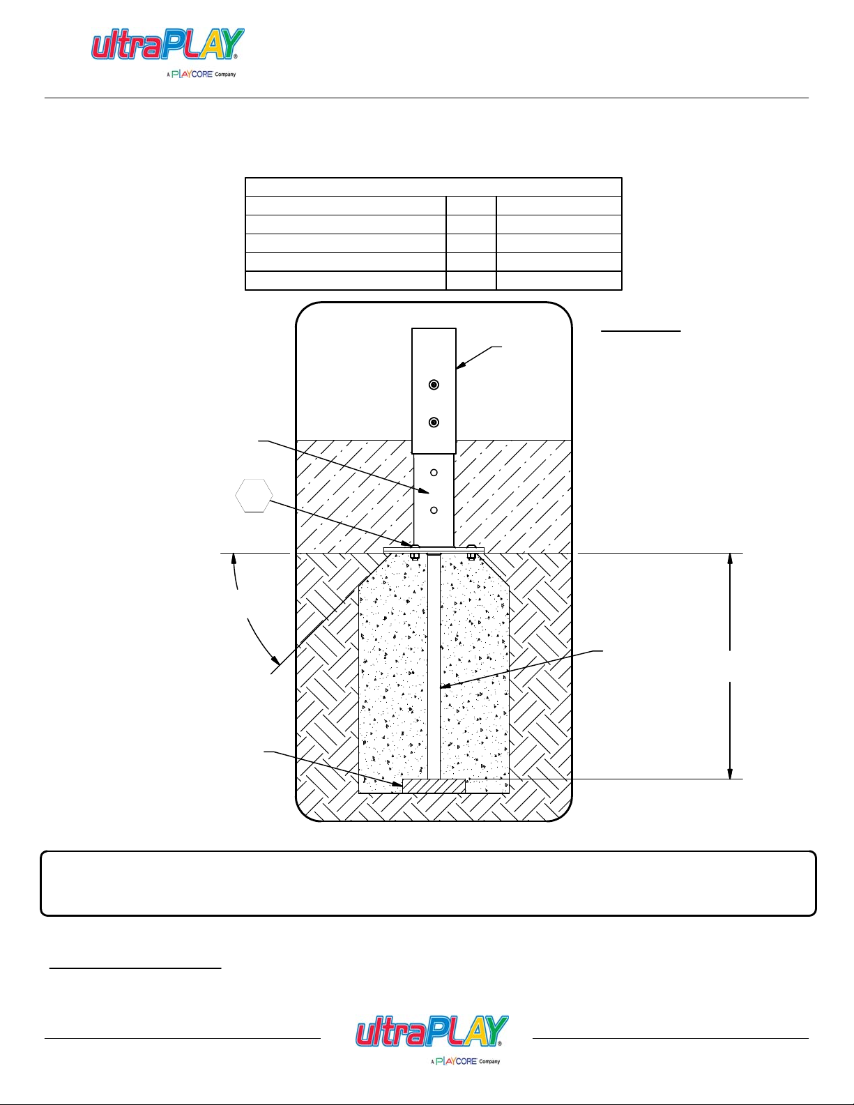
FOOTING DETAIL - IN GROUND
(33-12-0106)
Parts List
PART NUMBER
02-07-004935INGROUND FOOTER
33-05-0019105
33-02-00021053/8" FLAT WASHER
33-01-0002105
UPRIGHT
UPRIGHT
FOOTER
069
QTYDESCRIPTION
3/8" x 1 1/4" P.B.H.C.S. w/PATCH
3/8" HEX NUT
SURFACING
IMPORTANT:
UPRIGHTS WILL COME
PRE-ASSEMBLED WITH
UPRIGHT FOOTER
POSITIONED IN THE
BOTTOM (2) HOLES TO
ACCOMODATE 2" OF
SURFACING. WHEN
INSTALLING 12" OF
SURFACING, REMOVE
BOLTS AND ADJUST
UPRIGHT FOOTER
POSITION TO UTILIZE
THE TOP (2) HOLES.
45°
REF.
INGROUND
FOOTER
PLACE BRICK OR EQUIVALENT
IN THE BOTTOM OF ALL FOOT I NG
HOLES TO PREVENT POST FROM
SINKING INTO THE GROUND
18 in
[45.72 cm]
EARTH
IMPORTANT: Never install play equipment over hard, unresilient surfaces such as asphalt, concrete,
or compacted earth. It is the owner's responsibility to ensure the "minimum area required" contains an
appropriate amount of resilient material to cushion accidental falls.
SITE PREPARATION
Clear area of any debris and level surface. Equipment is designed to be installed on a level surface.
Issued/Revised:
800.458.5872
02/03/14
www.ultraplay.com
24
INCH0
1
2
365
4
5
1
0
CM
2
4
3
7
10961114815
12 13
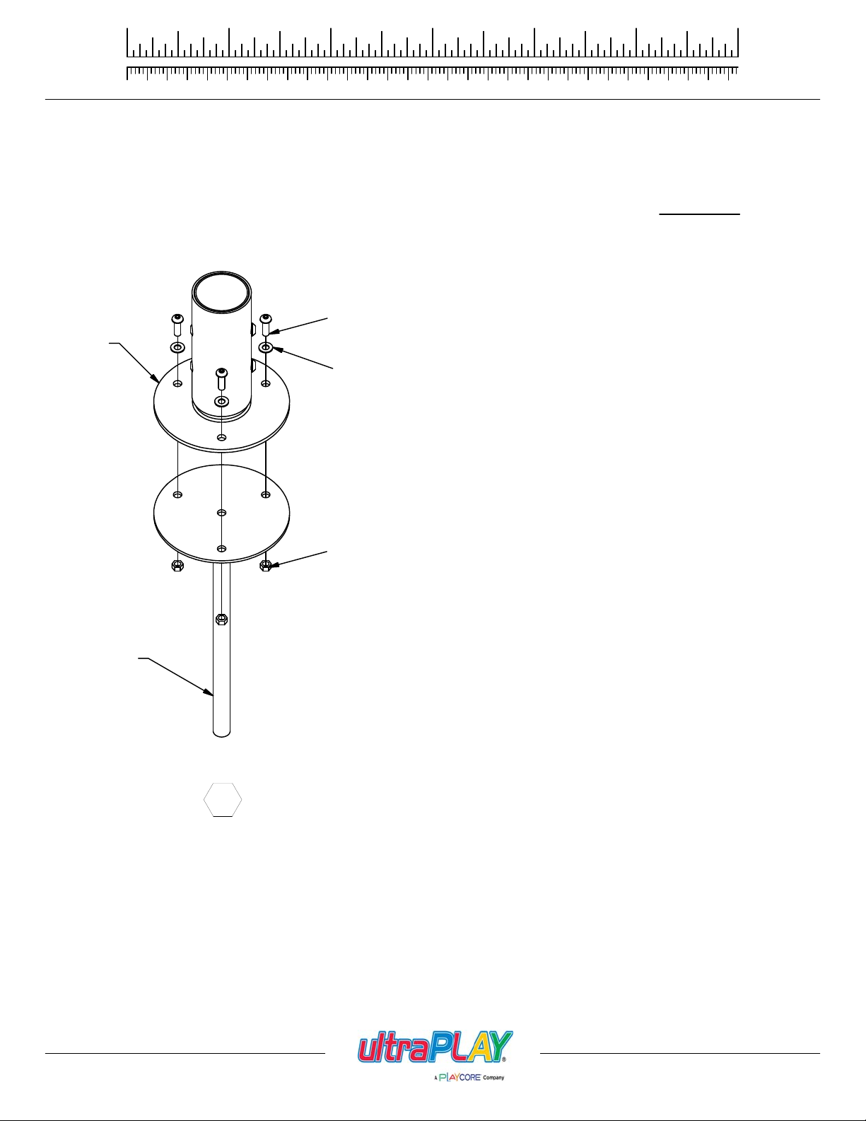
FOOTING DETAIL - IN GROUND
1. Attach Inground Footer to Upright Post using 3/8" x 1 1/4" P.B.H.C.S., 3/8" Flat Washer, and 3/8" Hex Nut. Refer to Footing Table
and Footing Layout page for Hole/Footer location. See Detail 069.
2. Continue assembling unit before pouring concrete. Refer to specific component installation instructions. IMPORTANT:
CONCRETE IS THE VERY LAST STEP!
3/8" x 1 1/4"
P.B.H.C.S. w/PATCH
(33-05-0019)
UPRIGHT
3/8" FLAT WASHER
(33-02-0002)
POURING
INGROUND
FOOTER
069
3/8" HEX NUT
(33-01-0002)
Issued/Revised:
800.458.5872
02/03/14
www.ultraplay.com
25
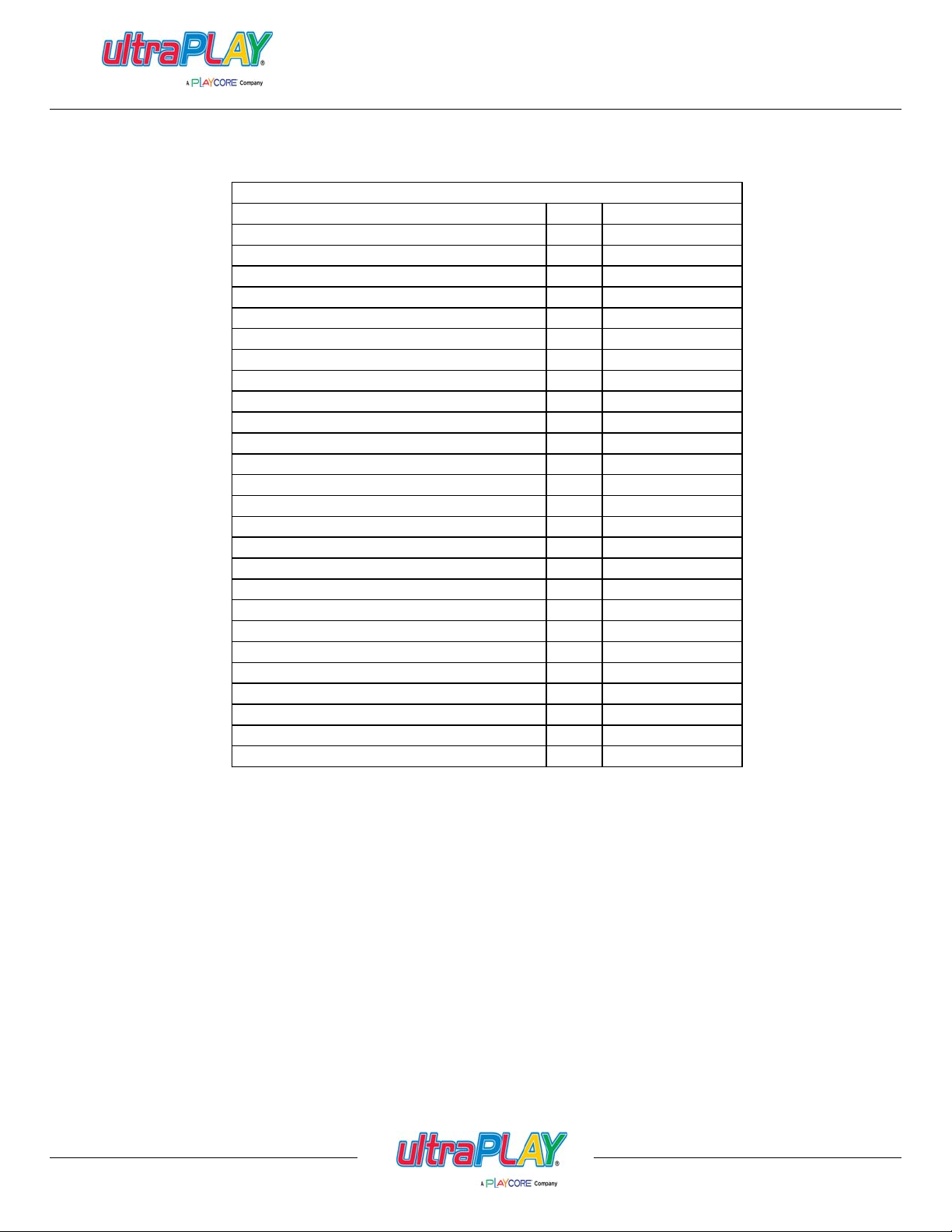
uPLAY TODAY
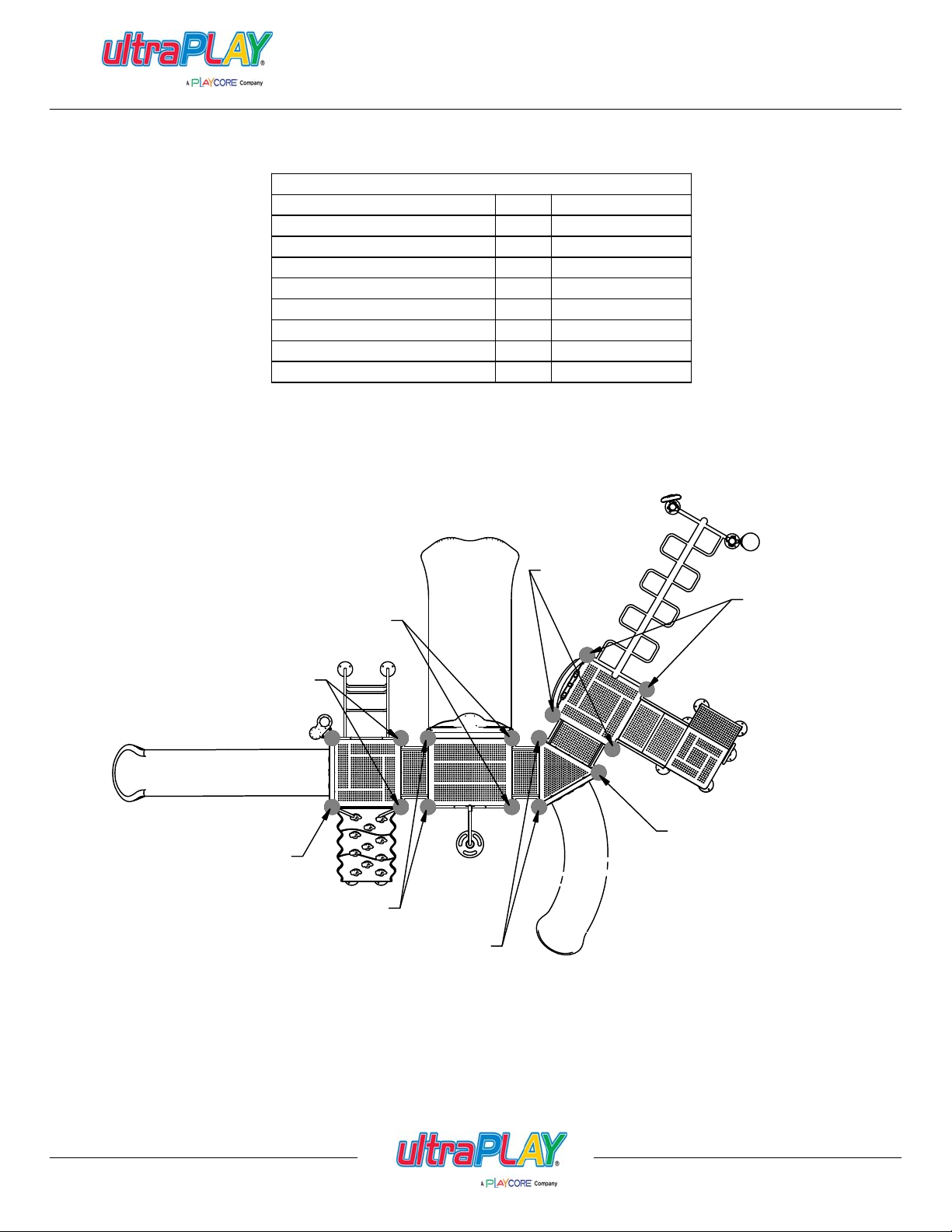
SLIDE MOUNTAIN
PANEL CLAMP
SQUARE DECK
4FT RIGHT CURVED SLIDE
6FT. WAVE SLIDE
SHIP'S WHEEL PANEL
HDPE CLIMBER
6FT. RUNG CLIMBER
RAINWHEEL w/TUBE CLAMP
BONGO DRUMS
RECTANGLE DECK
OVERHEAD LADDER
1 FT STAIRS
6'-11" UPRIGHT
7'-8" UPRIGHT
8'-8" UPRIGHT
9'-6" UPRIGHT
Parts List
QTYDESCRIPTION
PART NUMBER
02-07-00398TUBE CLAMP
02-07-00406
02-07-50012
02-07-50051
02-07-50061
02-07-50121
02-07-50181
02-07-50191
02-07-50221
02-07-50231BASS DRUM w/TUBE CLAMP
02-07-50241
02-07-50371TRIANGLE DECK
02-07-50381
02-07-503913FT ADA STEPS
02-07-50421
02-07-506015FT BEANSTALK CLIMBER -WIDE02-07-50643
02-07-506515FT DOUBLE STRAIGHT SLIDE
02-07-50742
02-07-507527'-6" UPRIGHT
02-07-50251
02-07-502628'-4" UPRIGHT
02-07-50762
02-07-507729'-5" UPRIGHT
02-07-50272
02-07-507829'-8" UPRIGHT
Warning: During Installation, Hardware And Small Parts Are Choking Hazards For Young Children. Store
Issued/Revised:
800.458.5872
Unless Otherwise Specified, All Units of Measure are Each
Items listed below Hardware Complete line are included with Hardware Complete Number
Unused Parts Appropriately Until Assembly Is Completed. Once Assembly Is Completed, Remove Any
Unused Parts From The Play Environment And Dispose/Save Them In A Secure Location. Any bolt end
protruding more than two full threads beyond the face of the nut causes risk of clothing entanglement.
Promptly cut-off flush, file smooth, and treat to prevent corrosion.
Note: Peen Tee-Nuts and Flatwashers to match radius of pipe after assembly is complete.
Note: Loctite (supplied by others) should be used on any non-patch hardware.
02/03/14
www.ultraplay.com
26
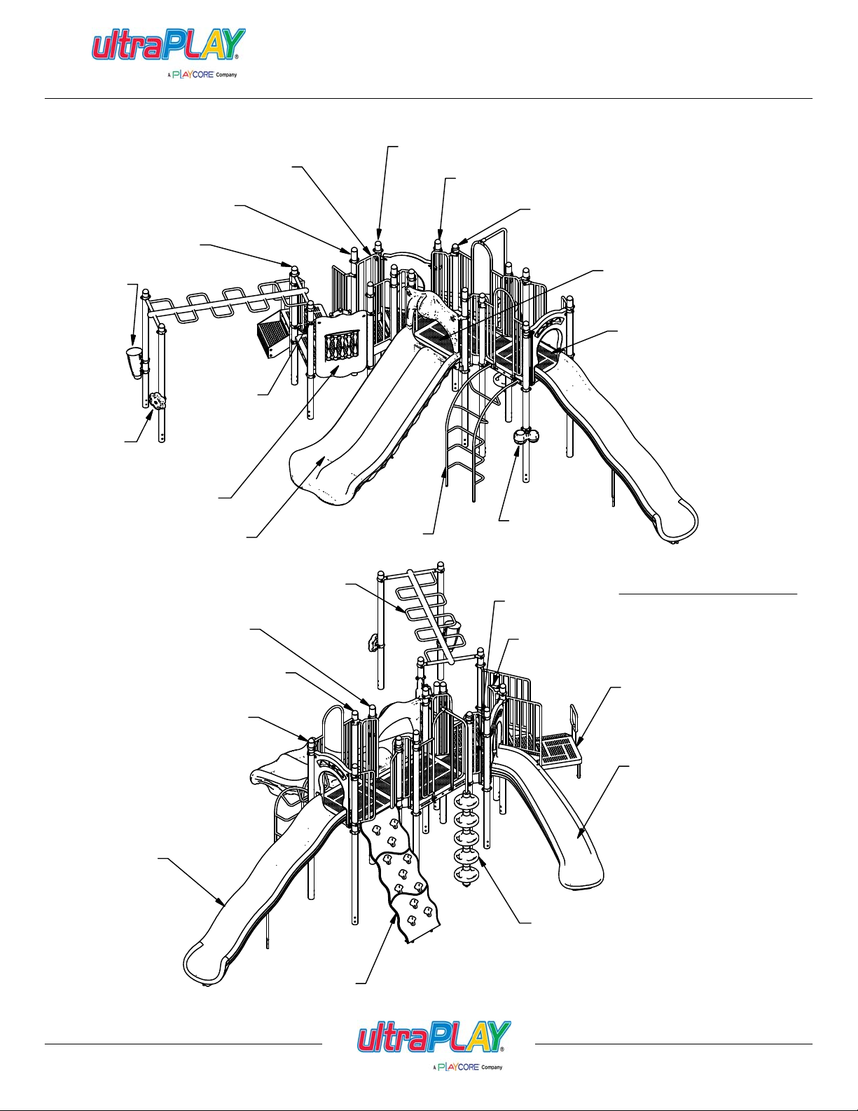
6'-11" UPRIGHT
BASS DRUM
(02-07-5023)
RAINWHEEL
(02-07-5022)
7'-6" UPRIGHT
(02-07-5075)
(02-07-5074)
PANEL CLAMP
(02-07-0040)
1FT STAIRS
(02-07-5064)
uPLAY TODAY
SLIDE MOUNTAIN
7'-8" UPRIGHT
(02-07-5025)
8'-4" UPRIGHT
(02-07-5026)
8'-8" UPRIGHT
(02-07-5076)
RECTANGLE DECK
(02-07-5038)
SQUARE DECK
(02-07-5001)
SHIP'S WHEEL PANEL
(02-07-5012)
5FT DOUBLE STRAIGHT
SLIDE (02-07-5065)
6FT WAVE SLIDE
(02-07-5006)
OVERHEAD LADDER
9'-5" UPRIGHT
(02-07-5077)
9'-8" UPRIGHT
(02-07-5078)
9'-6" UPRIGHT
(02-07-5027)
6FT RUNG CLIMBER
(02-07-5042)
(02-07-5019)
BONGO DRUMS
(02-07-5024)
TRIANGLE DECK
(02-07-5037)
TUBE CLAMP
(02-07-0039)
FINISHED ASSEMBLY
MODEL # UPLAY-015-N
MODEL # UPLAY-015-P
3FT ADA STEPS
(02-07-5039)
4FT RIGHT CURVED SLIDE
(02-07-5005)
Issued/Revised:
800.458.5872
02/03/14
HDPE CLIMBER
(02-07-5018)
5FT BEANSTALK
CLIMBER -WIDE(02-07-5060)
www.ultraplay.com
27
155 1/2 in
[394.92 cm]
11
12
.
m
i
D
l
a
c
i
t
r
e
V
16
6
2928
17
23
FOOTING TABLE
Hole No.
1
2
3
4
5
60 0 0
34
35
32
33
23
31
26
27
24
21
13
5
1
14
Horizontal Dim.
25
22
15
30
18
7
8
19 20
910
4
7
8
9
10
11
12 55"
13
14
15
16 0
17
18
19
20
21
22
23
24
25
26
27 198"
28
29
30
31
32
33
34
35
Hor. Dim.
122"
10 1/2"
26 1/4"
74"
140 1/4"
36 3/4"
51 1/2"
96 1/4"
111"
108 3/4" 18 1/2" 110 1/4"
142 3/4" 18 1/2"
177 1/2" 21 1/2"
200 1/2"
36 3/4" 36 3/4"
51 1/2" 36 3/4" 63 1/4"
96 1/4" 36 3/4" 103 1/4"
111"
150 1/4"
212 3/4" 28 1/2" 214 1/2"
118 1/4" 49 1/2" 128 1/4"
190 3/4"
218 1/2"
168 1/2"
7"
29 3/4" 73 3/4" 79 1/2"
74"
136 3/4" 81 1/4"
62 3/4" 127 1/4"
85"
182 1/2" 160 3/4" 243 1/4"
214 1/2" 142 1/2" 257 1/2"
Ver. Dim.
68 1/2"
38"
38"
20"
34"
00
00
00
00
18 1/2"
12"
36 3/4"
36 3/4"
31"
44"
42"
63" 180"
53 3/4" 205 1/4"
73 3/4" 74 1/4"
76 1/4" 106 1/4"
127 1/4" 153 1/4"
Diagonal
140"
39 1/2"
46 1/4"
76 1/2"
144 1/4"
58"
144"
179"
200 3/4"
0
52"
117"
153 1/4"
195 3/4"
222 1/2"
159"
142"
301 in
[764.53 cm]
IMPORTANT: Never install play equipment over
hard, unresilient surfaces such as asphalt,
concrete,or compacted earth. It is the owner's
responsibility to ensure the
"minimum area required" contains an
appropriate amount of resilient material to
cushion accidental falls.
Placement for
12" Diameter x 18" Deep Holes
for In-ground installation
IMPORTANT:
POURING CONCRETE IS THE VERY
LAST STEP!
Concrete Required (if applicable):
Approx: 1.53 Cubic Yards (1.17 Cubic Meters)
NOTE: Suggested Min. concrete rating: 3000PSI
1. Review Use Zone. Mark the placement of one Deck Post #6. Create a horizontal line and a vertical
line with strings so you can use the footing table. All diagonal dims are from the center of hole #6 to
the center of any other hole. NOTE: Survey flags may be used to mark the placement of each
hole.
2. Measure from first Deck Post to mark the position of the remainig (3) posts. Check for squareness
using the 52" diagonal dimension.
3. Measure from the center of a Deck Post using the dimensions provided for each remaining hole.
 Loading...