


KCMU000367
01/14/02
KC4200MX
ULTRA MINIATURE
1/3" MONOCHROME
CAMERA
USER MANUAL
KCMU000367
01/14/02
KC4200MN/KC4200MP

CAUTION
RISK OF ELECTR IC SHOCK
DO NOT OPEN
CAUTION: TO REDUCE THE RISK OF ELECTRIC SHOCK, DO NOT REMOVE
COVER (OR BACK). NO USER-SERVICEABLE PARTS INSIDE.
REFER SERVICING TO QUALIFIED SERVICE PERSONNEL.
The lightning flash with arrowhead symbol, within
an equilateral triangle, is intended to alert the
user to the presence of uninsulated "dangerous
voltage" within the product's enclosure that may
be of sufficient magnitude to constitute a risk of
electric shock to persons.
The exclamation point within an equilateral
triangle is intended to alert the user to the
presence of important operating and maintenance
(servicing) instruction in the literature
accompanying the product.
WARNING: TO PREVENT THE RISK OF
FIRE OR ELECTRIC SHOCK HAZARD,
DO NOT EXPOSE THIS CAMERA TO
RAIN OR MOISTURE.
Information for USA: This device
complies with Part 15 of the FCC rules.
Changes or modifications not approved by
ULTRAK could void the user’s authority to
operate the equipment.
Due to design modification, data given in
the user manual are subject to possible
change without prior notice.
ISSUE 1 2 KCMU000367
01/14/02

Thank you for purchasing the ULTRAK Ultra Miniature black-and-white CCD camera. Before using
this camera, please read the manual carefully to obtain the best results and keep the manual for
future reference.
TABLE OF CONTENTS
PRECAUTIONS................................................................................................................................. 4
FEATURES ....................................................................................................................................... 5
FEATURES AND FUNCTIONS – CAMERA SIDE ........................................................................... 6
FEATURES AND FUNCTIONS – CAMERA BACK .......................................................................... 8
SETUP SWITCH ............................................................................................................................. 10
LENS INSTALLATION AND ADJUSTMENT .................................................................................. 13
Mounting A Lens...................................................................................................................... 14
Backfocus Adjustment ............................................................................................................. 15
Lenses That Can Be Used ......................................................................................................16
SPECIFICATIONS........................................................................................................................... 17
SUPPLIED ACCESSORIES............................................................................................................19
ISSUE 1 3 KCMU000367
01/14/02

PRECAUTIONS
Handling
• Do not disassemble the camera and never touch parts inside the camera.
• When attaching or removing the lens, handle with care so that moisture and dust do not enter
the camera.
Installation and storage
• Do not point the camera at the sun. This could damage the camera whether it is operating or
not.
• Be sure the ambient temperature is less than 40°C for long-term continuous operation.
• Avoid installing in humid or dusty places.
• Avoid installing in places where there are strong magnetic fields or electrical signals.
• Avoid installing in places where the camera would be subject to strong vibrations.
• Never expose the camera to rain or water.
Cleaning
• Turn the power off and wipe off the dirt with a dr y soft cloth. If the camera is extremely dirty,
use furniture cleaning tissue.
• Do not use alcohols, petroleum distillates, liquid cleaners or sprays.
ISSUE 1 4 KCMU000367
01/14/02

FEATURES
High Sensitivity
• 1/3” 270,000 pixels CCD with on-chip micro lenses and low noise signal processing circuit
provide high sensitivity down to 0.25 lux (F1.2).
High Quality Image
• Horizontal resolution of 380 TV lines.
• High quality image is obtained by low noise signal processing with multi-layer PCB.
Backlight Compensation
• When strong light enters the scene background, such as from a spotlight or window, the
backlight compensation function automatically adjusts the video level to preserve visibility in
important sections of the image.
CCD Iris Function
• The electronic shutter function allows shutter speeds up to 1/100,000 sec. CCD iris function
automatically sets the brightness of the picture by changing the shutter speed of the camera
according to the incident light when using a manual iris lens.
ISSUE 1 5 KCMU000367
01/14/02

FEATURES AND FUNCTIONS - CAMERA SIDE
KC4200MN
1. Lens mount
2. Backfocus screw
4. C-mount adapter
5. Tripod mounting base
3. Lens
mount
cap
ISSUE 2 6 KCMU000367
01/18/02

FEATURES AND FUNCTIONS – CAMERA SIDE, CONTINUED
1. Lens mount
Mount for installing the lens. C-mount lens can be used when C-mount adapter is attached, and
CS-mount lens can be used when it is removed.
2. Backfocus screw
A screw is provided to fix the lens mount.
3. Lens mount cap
Cap the lens mount when the lens is not mounted.
4. C-mount adapter
Used to mount a C-mount lens. Turn counterclockwise to remove the C-mount adapter to mount
a CS-mount lens.
5. Tripod mounting base
Mounting base for installing the camera.
ISSUE 1 7 KCMU000367
01/14/02

ISSUE 1 8 KCMU000367
01/14/02
FEATURES AND FUNCTIONS - CAMERA BACK
5. Lens
Connector
3. Power
Indicator
1. Video
output
connector
2. Set-up
switch
4. Power
Input
Terminal
ON
OFF
VIDEO
BLC F.LAGC
LENS
PWR
GAMMAESC
12VDC

ISSUE 1 9 KCMU000367
01/14/02
FEATURES AND FUNCTIONS - CAMERA BACK, CONTINUED
1.Video output connector
BNC connector that outputs a composite video signal.
2. Set-up switch
Switch for camera setup according to the operating circumstances.
3. Power indicator
Indicator lights when the camera is powered.
4. Power input terminal
Connect to a 12V dc power source.
5. Lens connector
When using an auto-iris lens, connect the lens cable to this connector.
IMPORTANT: Do not connect the power source
until all other connections are completed.

SETUP SWITCH
1. AGC (Automatic Gain Control)
When AGC is ON, the camera’s sensitivit y is automaticall y
increased when the level of ambient light drops.
AGC function automatically controls signal gain in the range of
32dB (max).
2. ESC (Electronic Shutter Control)
When using the manual lens, the brightness of the picture
image will be fixed by setting ESC to ON, as the shutter speed
is automatically varied in the range of 1/60 to 1/100,000 sec.
according to the incident light. Set the ESC switch to OFF
when using the VIDEO type auto iris lenses.
NOTE: Outdoor illumination levels may exceed
150,000 lux, which is outside the range that can
be controlled by the electronic shutter. For proper
operation of electronic shutter, use an auto iris
lens if illumination levels exceed 10,000 lux.
ISSUE 1 10 KCMU000367
AGC FLBLC
ON
OFF
ESC GAMMA
AGC FLBLC
ON
OFF
ESC GAMMA
01/14/02

SETUP SWITCH, CONTINUED
3. BLC (Backlight Compensation)
Strong light, such as a spotlight, entering the scene
background causes the lens iris to close, possibly obscuring
desired portions of the scene. The Backlight compensation
function automatically adjusts the video level to preserve
visibility in important sections of the scene.
4. GAMMA
When the camera is used in applications such as image
processing, setting GAMMA to OFF causes the video signal to
become proportional to the brightness of the object, and therefore
makes it suitable for image processing. When viewed on a
monitor, however, dark areas of the image are excessively dark.
ISSUE 1 11 KCMU000367
AGC FLBLC
ON
OFF
ESC GAMMA
AGC FLBLC
ON
OFF
ESC GAMMA
01/14/02

SETUP SWITCH, CONTINUED
5. FL (Flickerless)
Flickerless mode can overcome flickering on the screen when
the AC power frequency is different from the vertical sync
frequency of the camera.
If the camera is used with 50Hz fluorescent lighting, there is
flicker on the screen, and the FL switch should be set to ON.
When used with a 60Hz power source, the FL function should
be OFF.
AGC FLBLC
ON
OFF
ESC GAMMA
ISSUE 1 12 KCMU000367
01/14/02
ISSUE 1 13 KCMU000367
01/14/02
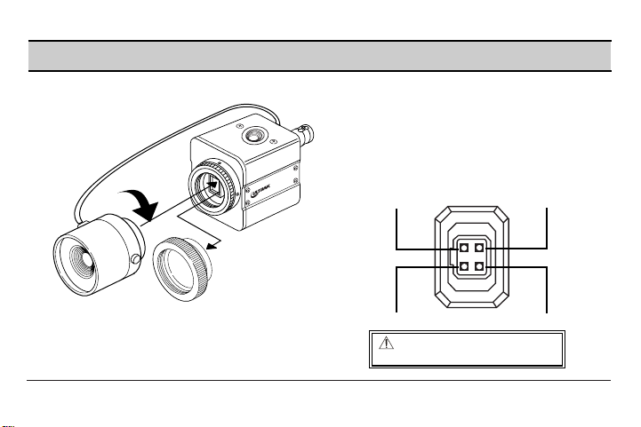
LENS INSTALLATION AND ADJUSTMENT
When using the VIDEO type Auto-iris lens,
install the lens plug as follows.
If the plug on the cable is of a different type,
replace it with the provided 4-pin iris plug.
DC type auto iris lens do not
work with this camera.
+12V dc
Video Signal
N.C.
GND
• ESC switch on the rear panel
should be set to ON when
using a manual lens.
N
4200M
C
K

ISSUE 2 14 KCMU000367
01/14/02
LENS INSTALLATION AND ADJUSTMENT, CONTINUED
Mounting A Lens
1. Remove the lens mount cap from the camera.
2. Attach or remove the C-mount adapter depending on the lens
to be used.
• If the adapter is attached so tightly that it is difficult to remove,
use long- nosed pliers to remove it. Insert the tips of the pliers
into the holes with no threads and turn to remove.
• A screwdriver can also be used to remove a firmly attached
adapter. Insert M3 screws into the holes so that the screwdriver
has something to grip.
Store the C-mount adapter for possible future use.
3. Attach the lens to the lens mount. Secure it so that it does not become loose.
4. If the lens has an auto-iris mechanism, connect the lens cable to the lens connector.
ADJUSTING AUTO-IRIS LENS
Connect the camera to a power source and monitor, then adjust the auto-iris lens.
1. Set AGC mode to OFF.
2. When using a video-type lens, adjust the level on the lens to produce minimum smear and
optimum pictures.
3. Set AGC mode to ON. It is recommended that the AGC be used in the ON mode after
adjusting the video level.

ISSUE 1 15 KCMU000367
01/14/02
LENS INSTALLATION AND ADJUSTMENT, CONTINUED
Backfocus Adjustment
When a lens is mounted, adjustment of the backfocus may be required.
Adjust with the lens focus ring when the correct focus cannot be obtained.
After selecting, press SET to return to the MAIN MENU.
WITH A FIXED-FOCUS LENS
1. Fully open the aperture and set the focus ring to ∞(infinity).
If using an auto-iris lens, shoot a comparatively dark object so that
the aperture is fully open.
2. Loosen the two backfocus screws with a hex wrench and turn the
lens mount to focus.
3. After adjusting the backfocus, tighten the backfocus screw.
4. Adjust iris for proper image quality.
WITH A VARIFOCAL LENS
1. Fully open the aperture and set the lens to the maximum telephoto position, then turn the focus
ring to focus. If using an auto-iris lens, shoot a comparatively dark object so that the aperture is
fully open.
2. Set the lens to its maximum wide-angle position.
3. Loosen the two backfocus screws with a hex wrench and turn the lens mount to focus. After
adjusting the backfocus, tighten the backfocus screws.
4. Repeat steps 1 through 3 until the difference between focusing position “Tele” and “Wide”
becomes smallest.
KC4200MN
Backfocus screw

ISSUE 1 16 KCMU000367
01/14/02
LENS INSTALLATION AND ADJUSTMENT, CONTINUED
Lenses that can be used
Ø
The camera can use C-mount lenses when the C-mount
adapter (standard accessory) is installed.
When removed, CS-mount lenses can also be used.
Ø
Use a suitable lens for the required area of view.
The area of view for different focal length can be obtained
using the following formula.
Mounted 1/2” 1/3”
Lens Lens Lens
A 4.8 3.6
B 6.4 4.8
Lens
Back Clearance
-focus “L”
C-mount 17.53 Less than
lens * mm 9mm
CS-mount 12.5 Less than
lens ** mm 4mm
Recommended
focal point
* With the C-mount adapter attached
** With the C-mount adapter removed
Note:“L” in the illustration should be
as shown in the table. If “L” exceeds
the value in the table, it may damage
the inside of the camera and correct
mounting may be impossible. Be sure
not to attach the C-mount adapter
when using a CS-mount lens.
Height of the area of view(m) =
A x Distance between camera and object (m)
Focal length of lens(mm)
Width of the area of view(m) =
B x Distance between camera and object (m)
Focal length of lens(mm)
L
Lens
Back-focus

ISSUE 1 17 KCMU000367
01/14/02
SPECIFICATIONS
ITEMS SPECIFICATIONS
Signal system KC4200MN(EIA) / KC4200MP(CCIR)
CCD Pickup element Interline transfer 1/ 3" CCD
Effective pixels EIA:510(H) x 492(V) / CCIR:500(H) x 582(V)
Scanning area 6.0(H) x 4.96(V) mm
Scanning frequency Horizontal: 15. 743kHz / Vertical: 59. 94Hz (EIA)
Horizontal: 15. 625kHz / Vertical: 50Hz (CCIR)
Sync system Internal
Video output Composite video signal (1Vp- p, 75Ohm, unbalanced)
Video S/ N ratio 50dB (AGC OFF)
Horizontal resolution 380 TV lines
Minimum illumination 0. 25 lux (F1. 2, 50IRE, AGC ON)
Auto electronic shutter ON/ OFF selectable
(EIA:1/60~1/100,000 second CCIR:1/50~1/100,000 second)
AGC ON/ OFF selectable (32dB)
Backlight compensation ON/ OFF selectable

SPECIFICATIONS, CONTINUED
ITEMS SPECIFICATIONS
GAMMA ON/OFF (0.45/1) selectable
Flickerless ON/OFF selectable
Auto-iris lens outputs
Lens mount C/CS mount
Camera mount 1/4"-20 UNC (Top/Bottom)
Power requireme t Regulated 12V dc (11V dc ~ 13V dc)
Power consumption 1.5 watts Max.
Operating temperature 14°F to 122°F (-10°C to +50°C)
Storage temperature -4°F to 140°F (-20°C to +60°C)
External dimensions 1.6W x 1.6H x 2.1D inches (41W x 41H x 53D mm)
Weight 0.31 lbs (140g)
Note: If used continuously, operate at less than 40°C (140°F) for long-term stable performance.
ISSUE 1 18 KCMU000367
Video-type lens: Luminance signal 1Vp-p, high impedance,
power supply 12V dc 50mA
01/14/02

SUPPLIED ACCESSORIES
DC Jack Plug (MP-121M) 1
Lens mount cap 1
C-mount adapter 1
L wrench 1
User manual 1 Model No. Serial No.
• The lens mount cap and C-mount adapter are attached when supplied.
Notes:
• Design and specifications are subject to change without notice.
• This CCD camera is designed to output video signals conforming to the EIA/CCIR standard
(depending on model), so it cannot be used with video recorders or black-and-white monitors
which use signal systems other than EIA/CCIR.
ISSUE 1 19 KCMU000367
For Customer Use :
Please record the Model No. and Serial No. in
the spaces provided below. These numbers
are located on the bottom of the camera.
Keep this manual for future reference.
01/14/02

ULTRAK WORLDWIDE OFFICES
Ultrak Worldwide Support Center
Sales & Technical Support
1301 Waters Ridge Drive • Lewisville, TX 75057
(800) 796-2288 • (972) 353-6400 • FAX: (972)353-6670
(972) 353-6500 (Corporate Office)
info@ultrak.com
Ultrak Asia
221 Henderson Road • #06-18 Henderson Building
Singapore 159557 • China
+65 (2) 734 126 • FAX: +65 (2) 734 139
Ultrak Germany
Großenbaumer W eg 8 • D-40472 •Düsseldorf , Germany
+ 49 (0) 211 4150 90 • FAX: + 49 (0) 21 1 424019
info@ultrak-germany.com
Ultrak Poland
Ul. Niedzialkowskiego 24 • 71-410 Szczecin, Poland
+ 48 (0)91 423 20 61 • FAX: + 48 (0)91 423 20 63
Ultrak South Africa
Unit 6 • Galaxy Park • 17 Galaxy Avenue
Linbro Park • 2065 • Johannesburg, South Africa
+ 27 (0)11 608 22 51 • FAX: + 27 (0)1 1 608 1929
info@ultra k-southafric a.com
ABM Data Systems – An Ultrak Co.
9020 Capital of Texas Highway North
Suite 540 • Au stin, TX 78759
(512)345-6900 • (800) 767-7067 (Sales)
FAX: (512) 34 5-3252
Ultrak Asia Pacific
Unit 1 • 25 Barker Street
Belmont, Western Australia 6104
+61 8 9475 2800 Fax: +61 8 9478 4500
sales@ultrak.com.au
Ultrak Italy
Via Treviso • 2/4 • 31020 San Vendemiano • Treviso, Italy
+ (39) 0438 36 51 • FAX: + (39) 0438 370471
info@ultrak-italy.com
Ultrak Switzerland
Ch. Du Closalet 4 • 1023 Crissier • Switzerland
+ 41 (0)21 671 04 01 • FAX: + 41 (0)21 671 04 02
info@ultrak-switzerland.com
Ultrak UK
Carnoustie House • The Links • Kelvin Close • Birchwood •
Warrington, WA3 7PB, UK
+ 44 (0)1925 844 200 • FAX: + 44 (0) 19 258 44 201
info@ultrak-uk.com
ISSUE 1 20 KCMU000367
01/14/02
 Loading...