

Page 1
30A134 Mar 2009
14" MODEL PAR-3-H CE GAS FRYER
WITH HARD DOCK FILTRATION
Operating Instructions
302 Spencer Lane • P.O. Box 5369 San Antonio, Texas 78201
(800) 525-8130 • (210) 731-5000 • Fax: (210) 731-5099
www.ultrafryer.com
THIS APPLIANCE IS FOR PROFESSIONAL USE AND IS TO BE USED ONLY BY QUALIFIED PERSONNEL
Page 2

PREFACE
This Manual was written and published by the Engineering Department, Ultrafryer Systems for use by personnel who will operate a 14" Model
PAR-3-H CE Gas Fryer equipped with a Hard Dock Filtration System in a commercial cooking environment.
ENGINEERING DEPARTMENT
ULTRAFRYER SYSTEMS
302 SPENCER LANE
SAN ANTONIO, TX 78201
THIS APPLIANCE IS INTENDED FOR PROFESSIONAL USE AND IS TO BE OPERATING BY QUALIFIED PERSONNEL
Throughout this manual Notes, CAUTIONS and WARNINGS are used to alert the operator to items of special circumstances.
These items are identified as follows:
NOTES
These Items will be indented from the main text, the word “NOTE” will be in capital letters. These items alert the operator to items
of special concern to achieve a desired result.
Example:
NOTE: Pull on the filter tub to ASSURE the male docking plug is SEATED in the female bulkhead socket.
CAUTIONS: These items will be indented from the main body of text, the word “CAUTION” will be in bold, capitalized print and the entire
text will be enclosed by a border. These items identify steps or procedures that if not adhered to could result in
product, equipment malfunction or failure.
Example:
WARNINGS
These items will be indented from the main body of text, the word “WARNING” as well as the text will be in bold, capitalized print
and the entire text will be enclosed by a bold border. These items identify steps or procedures that if not adhered to could result in
property damage, injury or death.
Example:
NOTE: This manual is applicable to Ultrafryer Model Par3 14H CE Gas Fryer.
UFS PN 30A134
i 30A134
CAUTION: TO ASSURE PRODUCING A QUALITY PRODUCT WHILE PROLONGING THE LIFE
EXPECTANCY OF THE FRYER, ENSURE FILTERING, BOIL-OUT AND CLEANING
INSTRUCTIONS ARE STRICTLY ADHERED TO.
WARNING: DO NOT ALLOW ANY CLEANING SOLUTION OR WATER TO SPLASH INTO A VESSEL OF
HOT COOKING OIL, AS IT WILL CONTAMINATE THE OIL AND MAY CAUSE THE OIL TO
SPLATTER CAUSING SEVERE BURNS.
Page 3

TABLE OF CONTENTS
GENERAL INFORMATION PAGE
Preface Table of Contents . . . . . . . . . . . . . . . . . . . . . . . . . . . . . . . . . . . . . . . . . . . . . . . . . . i-iii
Safety. . . . . . . . . . . . . . . . . . . . . . . . . . . . . . . . . . . . . . . . . . . . . . . . . . . . . . . . . . . . . . . . . . 1
Description / Specifications. . . . . . . . . . . . . . . . . . . . . . . . . . . . . . . . . . . . . . . . . . . . . . . . . 1
Operational Requirements. . . . . . . . . . . . . . . . . . . . . . . . . . . . . . . . . . . . . . . . . . . . . . . . . . 1
Ultrastat 23 Cooking Computer. . . . . . . . . . . . . . . . . . . . . . . . . . . . . . . . . . . . . . . . . . . . . . 2
Operating Controls Location. . . . . . . . . . . . . . . . . . . . . . . . . . . . . . . . . . . . . . . . . . . . . . . . . 2
Operating Controls. . . . . . . . . . . . . . . . . . . . . . . . . . . . . . . . . . . . . . . . . . . . . . . . . . . . . . . . 3
Automatic Safety Features. . . . . . . . . . . . . . . . . . . . . . . . . . . . . . . . . . . . . . . . . . . . . . . . . . 4
European Pressures, Gases & Categories Table. . . . . . . . . . . . . . . . . . . . . . . . . . . . . . . . . 4a-4c
Installation, start up, and Initial Cleaning . . . . . . . . . . . . . . . . . . . . . . . . . . . . . . . . . . . . . 5
PRE-INSTALLATION
General . . . . . . . . . . . . . . . . . . . . . . . . . . . . . . . . . . . . . . . . . . . . . . . . . . . . . . . . . . . . . . . . . 6
Rating Plate. . . . . . . . . . . . . . . . . . . . . . . . . . . . . . . . . . . . . . . . . . . . . . . . . . . . . . . . . . . . . 6
Clearances. . . . . . . . . . . . . . . . . . . . . . . . . . . . . . . . . . . . . . . . . . . . . . . . . . . . . . . . . . . . . . 6
Standards. . . . . . . . . . . . . . . . . . . . . . . . . . . . . . . . . . . . . . . . . . . . . . . . . . . . . . . . . . . . . . . 6
Air Supply & Ventilation. . . . . . . . . . . . . . . . . . . . . . . . . . . . . . . . . . . . . . . . . . . . . . . . . . . . 6
RECEIVING & INSTALLING
Unpacking. . . . . . . . . . . . . . . . . . . . . . . . . . . . . . . . . . . . . . . . . . . . . . . . . . . . . . . . . . . . . . . 7
Installing. . . . . . . . . . . . . . . . . . . . . . . . . . . . . . . . . . . . . . . . . . . . . . . . . . . . . . . . . . . . . . . . 7
Leveling. . . . . . . . . . . . . . . . . . . . . . . . . . . . . . . . . . . . . . . . . . . . . . . . . . . . . . . . . . . . . . . . 7
Gas Connection . . . . . . . . . . . . . . . . . . . . . . . . . . . . . . . . . . . . . . . . . . . . . . . . . . . . . . . . . . 8
Electrical Connection. . . . . . . . . . . . . . . . . . . . . . . . . . . . . . . . . . . . . . . . . . . . . . . . . . . . . . 8
INITIAL START-UP
Cleaning. . . . . . . . . . . . . . . . . . . . . . . . . . . . . . . . . . . . . . . . . . . . . . . . . . . . . . . . . . . . . . . . 10
Start-Up. . . . . . . . . . . . . . . . . . . . . . . . . . . . . . . . . . . . . . . . . . . . . . . . . . . . . . . . . . . . . . . . 10
Lighting Instructions. . . . . . . . . . . . . . . . . . . . . . . . . . . . . . . . . . . . . . . . . . . . . . . . . . . . . . . 10
Sequence Of Ignition. . . . . . . . . . . . . . . . . . . . . . . . . . . . . . . . . . . . . . . . . . . . . . . . . . . . . . 10
Burner Operation Test. . . . . . . . . . . . . . . . . . . . . . . . . . . . . . . . . . . . . . . . . . . . . . . . . . . . . 10
Test Start-Up. . . . . . . . . . . . . . . . . . . . . . . . . . . . . . . . . . . . . . . . . . . . . . . . . . . . . . . . . . . . . 11
ABBREVIATED OPERATING INSTRUCTIONS
General . . . . . . . . . . . . . . . . . . . . . . . . . . . . . . . . . . . . . . . . . . . . . . . . . . . . . . . . . . . . . . . . . 12
Filtering Shortening. . . . . . . . . . . . . . . . . . . . . . . . . . . . . . . . . . . . . . . . . . . . . . . . . . . . . . . . 12
Leveling Shortening. . . . . . . . . . . . . . . . . . . . . . . . . . . . . . . . . . . . . . . . . . . . . . . . . . . . . . . 12
Boiling Out Fryer. . . . . . . . . . . . . . . . . . . . . . . . . . . . . . . . . . . . . . . . . . . . . . . . . . . . . . . . . . 12
Closing / Shutdown Instructions. . . . . . . . . . . . . . . . . . . . . . . . . . . . . . . . . . . . . . . . . . . . . . 12
PREVENTIVE MAINTENANCE & TROUBLESHOOTING
Preventive Maintenance . . . . .. . . . . . . . . . . . . . . . . . . . . . . . . . . . . . . . . . . . . . . . . . . . . 13
Troubleshooting. . . . . . . . . . . . . . . . . . . . . . . . . . . . . . . . . . . . . . . . . . . . . . . . . . . . . . . . . . 13
Troubleshooting Chart. . . . . . . . . . . . . . . . . . . . . . . . . . . . . . . . . . . . . . . . . . . . . . . . . . . . . 14
ii 30A134
Page 4

TABLE OF CONTENTS.....Continued
CLEANING
General . . . . . . . . . . . . . . . . . . . . . . . . . . . . . . . . . . . . . . . . . . . . . . . . . . . . . . . . . . . . . . . . . 15
Daily . . . . . . . . . . . . . . . . . . . . . . . . . . . . . . . . . . . . . . . . . . . . . . . . . . . . . . . . . . . . . . . . . . . 15-16
Weekly . . . . . . . . . . . . . . . . . . . . . . . . . . . . . . . . . . . . . . . . . . . . . . . . . . . . . . . . . . . . . . . . . 17
FRYER OPERATION
General . . . . . . . . . . . . . . . . . . . . . . . . . . . . . . . . . . . . . . . . . . . . . . . . . . . . . . . . . . . . . . . . . 18
Ultrastat 23 Cooking Computer. . . . . . . . . . . . . . . . . . . . . . . . . . . . . . . . . . . . . . . . . . . . . . . 19
Computer Panel Key Descriptions. . . . . . . . . . . . . . . . . . . . . . . . . . . . . . . . . . . . . . . . . . . . 20
Display Descriptions. . . . . . . . . . . . . . . . . . . . . . . . . . . . . . . . . . . . . . . . . . . . . . . . . . . . . . . 21
Ultrastat 23 Cooking Computer Operation. . . . . . . . . . . . . . . . . . . . . . . . . . . . . . . . . . . . . . 22
Ultrastat 23 Cooking Computer Programming. . . . . . . . . . . . . . . . . . . . . . . . . . . . . . . . . . . 22
Cooking. . . . . . . . . . . . . . . . . . . . . . . . . . . . . . . . . . . . . . . . . . . . . . . . . . . . . . . . . . . . . . . . . 23
Ultrastat 23 Start-Up and Cooking Computer Operation. . . . . . . . . . . . . . . . . . . . . . . . . . . 23
FILTER TUB ASSEMBLY & INSTALLATION
Filter Tub Assembly. . . . . . . . . . . . . . . . . . . . . . . . . . . . . . . . . . . . . . . . . . . . . . . . . . . . . . . 24
Filter Tub Installation. . . . . . .... . . . . . . . . . . . . . . . . . . . . . . . . . . . . . . . . . . . . . . . . . . . . . . 24
FILTERING & POLISHING SHORTENING
Filtering Shortening. . . . . . . . . . . . . . . . . . . . . . . .. . . . . . . . . . . . . . . . . . . . . . . . . . . . . . . . 25-26
Polishing Shortening. . . . . . . . . . . . . . . . . . . . . . . . . . . . . . . . . . . . . . . . . . . . . . . . . . . . . . 26
SHORTENING DISPOSAL, BOIL-OUT & REFILL
General . . . . . . . . . . . . . . . . . . . . . . . . . . . . . . . . . . . . . . . . . . . . . . . . . . . . . . . . . . . . . . . . . 27
Shortening Disposal. . . . . . . . . . . . . . . . . . . . . . . . . . . . . . . . . . . . . . . . . . . . . . . . . . . . . . . 27
Boil-Out. . . . . . . . . . . . . . . . . . . . . . . . . . . . . . . . . . . . . . . . . . . . . . . . . . . . . . . . . . . . . . . . . 27-28
Shortening Refill . . . . .. . . . . . . . . . . . . . . . . . . . . . . . . . . . . . . . . . . . . . . . . . . . . . . . . . . . . 28
TECHNICAL ASSISTANCE & ORDERING INFORMATION
Technical Assistance. . . . . . . . . . . . . . . . . . . . . . . . . . . . . . . . . . . . . . . . . . . . . . . . . . . . . . 29
Ordering Information. . . . . . . . . . . . . . . . . . . . . . . . . . . . . . . . . . . . . . . . . . . . . . . . . . . . . . 29
PARTS IDENTIFICATION
Parts Identification. . . . . . . . . . . . . . . . . . . . . . . . . . . . . . . . . . . . . . . . . . . . . . . . . . . . . . . . 30-34
WIRING DIAGRAM. . . . . . . . . . . . . . . . . . . . . . . . . . . . . . . . . . . . . . . . . . . . . . . . . . . . . . 35
iii 30A134
Page 5

A. SAFETY
As with all deep Fat Fryers the major safety concern associated with the Ultrafryer Par3-14 CE Gas Fryer is
burns from hot shortening. In order to prevent serious burns, good housekeeping habits are required. The floor
in front of and the area around the fryer should be kept clean and dry. Whenever anything is placed in to a fryer
vat, care should be used not to splash the hot shortening. Product should always be “PLACED” into the short-
ening, NOT THROWN. Safety goggles, neoprene insulated gloves and an apron must be worn while filtering
or boiling-out a fryer vat. Electrical controls on all Ultrafryer CE Fryers operate on 230 volts single phase electrical power. No adjustments or replacement of electrical controls should ever be attempted without first disconnecting electrical power. The fryer should never be operated with wet hands or while standing in water. To
do so can result in serious electrical shock or death.
B. DESCRIPTION / SPECIFICATIONS
The Ultrafryer Gas Fryer is constructed from 16 & 18 gauge, stainless steel, and is equipped with an Ultrastat
23 Cooking Computer. In addition, the fryer is equipped with the NEWLY developed Hard Dock Filtration
System that uses a stainless steel Filter Screen. The Customer has the option of ordering a Magnepad Filter
Screen that uses a Magnesol impregnated Filter Pad or a Paper filter pad in lieu of the S/S filter screen. The
dimensions, specifications and gas ratings are as follows:
SPECIFICATION ITEM 14" PAR-3-H CE
Overall Width 15 5/8" (397 mm)
Overall Depth 25 1/4" (641 mm)
Work Height 35 3/4" (908 mm)
Size Vat Container 14" x 14" (356 x 356 mm)
Shipping Cube 9.0 FT3 (.26 M3)
Shipping Weight 215 lbs (113 kgs)
Power Input 230 Volt 6 Amp 50 Hz 1 Ø
C. OPERATIONAL REQUIREMENTS
MODEL PAR-3-14HE CE OPERATIONAL REQUIREMENTS
ITEM PAR-3-14HE CE
Shortening Capacity High Level 45 lbs. (22.5 liters)
Shortening Capacity low Level 35 lbs. (17.5 liters)
Gas Valve Pressure Setting See Note Below
Orifice Drill Size See Note Below
Inlet Gas Pressure See Note Below
Energy Input 230 V 6 AMPS 50 HZ 1 Ø
NOTE: See European Pressures, Gases and Categories Table on page 4a -4c.
Page 1
30A134
This appliance is for Professional use and is to be used only by Qualified Personnel
GENERAL INFORMATION
Page 6

D. ULTRASTAT 23 COOKING CONTROL
This cooking computer is capable of cooking up to ten (10) different products; each of which can be programmed to be cooked
from one (1) to ten (10) different temperature at different times in
a cook cycle. In addition, the operator can program the UL-
TRASTAT23 computer to cook products under “flex” or
“STRAIGHT” timing modes. When programmed for “FLEX”
time mode the computer will adjust the actual cook time taking
into consideration the temperature variation due to load size, initial
product temperature, product moisture content, and other factors
that affect the cook cycle. Under “STRAIGHT” time mode, the product is cooked at a specified temperature for
the length of time programmed without adjusting for these variations. Operation of the ULTRASTAT23 cooking
computer is covered in the ULTRASTAT 23 Gas Fryer Computer Operating Instructions Manual PN 30A216
provided with the Fryer.
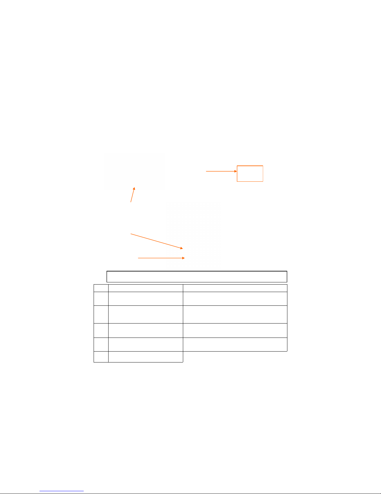
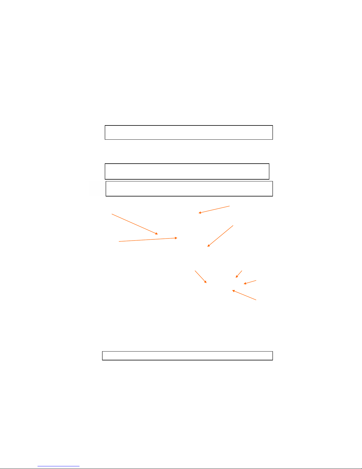
E. OPERATING CONTROLS LOCATION 14" MODEL PAR-3-H CE GAS FRYER
Controller
Venturi Ignition Cable
Electronic
Ignition
Module
Combo Electric
Gas Valve
Manual Shutoff
Valve
Service Access
Door
Filter Tub Hard
Docking Connection
Drain Valve
Drain Valve Safety
Microswitch
Spark Ignitor with
Bracket
Burner
Process
Temperature
Control Probe
Hi-Limit
Temperature
Probe
Page 2 30A134
Pilot Gas
Siphon Line
Page 7

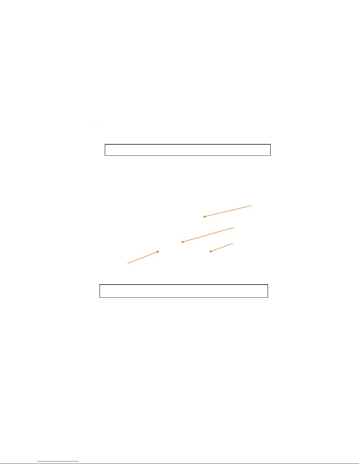
F. OPERATING CONTROLS:
The Model PAR-3-14 CE gas fryer is equipped an Ultrastat 23 Cooking Computer. Operating controls include
the On/Off Switch, AMBER Power Indicator Lamp, RED Burner Indicator Lamp, and the applicable Temperature Controller. These controls are mounted on the Temperature Control access Panel; and other fryer controls
are located behind the access door. The main drain valve and shortening return levers are located behind the Service Access door. These controls were identified in the illustrations shown on the previous page.
Topside Shortening
Return Lever (shown
Open)
Vat Shortening
Return Lever
(shown closed)
Drain Valve
Page 3
30A134
Page 8

G. AUTOMATIC SAFETY FEATURES:
1. High limit thermostat to shut off gas to the main burners by opening a solenoid -actuated safety
valve in the combination gas control valve.
2. Combination gas control valve which includes a built-in pressure regulator and manual valve.
3. Sensing circuit within the spark ignitor module to turn gas to the fryer OFF if a burner FLAME
OUT occurs.
4. A Drain Valve Safety Switch that will DISABLE the fryer each time the drain valve is OPENED.
5. An AIR PRESSURE switch to open the electrical circuit to the spark ignitor and gas valve which
will turn the gas to the fryer OFF in the event the blower fails.
H. EUROPEAN PRESSURE, GAS AND CATEGORIES TABLE
Page 4
30A134
Page 9

4a
30A134
Page 10

30A134
4b
Page 11

30A134
4c
Page 12

Page 5
30A134
Installation, Startup and Initial Cleaning
All installation and service on Ultrafryer equipment
must be performed by Qualified, Certified, Licensed,
and/or Authorized installation or service personnel.
Qualified personnel must be experienced in such work, be
familiar with all gas precautions involved, and have
complied with all requirements of applicable National and
local codes.
Page 13

A. GENERAL
Safe and satisfactory operation of a gas fryer depends on its proper installation. Installation must conform to national and/or
local codes Each fryer should be installed as follows:
1. Placed beneath a properly designed exhaust hood
2. Installed by a licensed plumber.
3. Connected to the type gas for which the unit was fabricated as shown on the rating plate.
4. Connected to the proper size pressure regulator installed in the gas supply line and adjusted to the proper manifold pressure.
5. Connected to the main gas supply line with the proper size supply line.
6. Restrained by use of a restraining chain device to avoid splashing of hot liquid and to assure tension cannot be placed on
the flexible gas line or fittings (see picture on page 7).
B. RATING PLATE
The rating plate on the 14" PAR-3-HE CE Gas Fryer is located on the inside of the service access door and contains the
following: Model and serial number, BTU/HR (MJ/HR) input rating of the burner; supply pressure in mbar Burner pressure;
orifice size and type gas as acquired from the European Pressures, Gases and Categories table on page 4a-4c.
Safe and satisfactory operation of a Par3-14H CE gas fryer depends upon proper installation. Installation must conform to
local codes
C. CLEARANCES
The appliance must be kept free and clear of all combustibles. The minimum clearance from combustible and noncombustible construction is 6" (152 mm) from the sides, and 6" (152 mm) from rear. The fryer may be installed on combustible floors.
NOTE: Adequate clearances must be provided for servicing and proper operation.
D. STANDARDS
Installation must be planned in accordance with all applicable National and local codes, taking into account the following
requirements.
1. The fryer and its individual shut-off valve must be disconnected from the gas supply piping system during any pressure
testing of that system at pressures in excess of 1⁄2 psig (3.45kPa).
2. The fryer must be isolated from the gas supply piping system by closing its individual manual shut-off valve during any
pressure testing of the gas supply piping system at pressures equal to or less than 1⁄2 psig (3.45kPa).
3. When installed the fryer must be electrically grounded in accordance with local codes.
NOTE: Local building codes will usually not permit a fryer with its open tank of hot oil to be installed immediately next
to an open flame of any type, whether a broiler or an open burner or range. Check local codes before beginning
installation.
E. AIR SUPPLY AND VENTILATION
The area around the appliance must be kept clear of any combustible or flammable products and avoid any obstruction to the
flow of ventilation air as well as for ease of maintenance and service. NOTHING is to be stored in the interior of the fryer‟s
cabinet except the filter tub assembly.
1. A means must be provided for any commercial, heavy duty-cooking appliance to exhaust combustion wastes outside of the
building. It is essential that a fryer be set under a powered exhaust vent hood or that an exhaust fan be provided in the wall
above the unit, as exhaust temperatures are in the vicinity of 400˚F (204˚C).
NOTE: Strong exhaust fans in a hood or in the overall air conditioning system can produce slight air drafts in the room,
which can interfere with burner performance and be hard to diagnose. Air movement should be checked during
installation and if burner problems persist, make-up air openings or baffles may have to be provided in the
room.
2. Exhaust temperature, in addition to the open tank of hot oil, make the storage of anything on shelving over or behind the
fryer unsafe.
3. Filters and drip troughs should be part of any industrial hood, but consult local codes before constructing and installing any
hood.
4. Provisions must be made for an adequate supply of fresh air and adequate clearance must be maintained for air openings
into the combustion chamber.
Page 6
30A134
The fryer must be connected only to the type of gas indentified on this rating plate.
PRE-INSTALLATION
Page 14

A. UNPACKING
Check that the container is upright and that the plastic wrap is securely strapped to the wooden skid. Check for visible dam
age; and if damage has occurred, do not refuse shipment, but contact the carrier and file the appropriate freight claims.
CAREFULLY remove the plastic wrap and straps; then remove the fryer from the skid.
B. INSTALLING
Roll the assembled fryer into the building, to it‟s operating location.
C. LEVELING
1. When the fryer is placed in its operating location check to be sure it is level. If not, loosen the casters and insert the appropriate number of shim plates between leg and caster plates then retighten the caster bolts.
2. If the floor is smooth and level, adjust to the high corner and measure with a spirit level. If the floor is uneven or has a
decided slope, level the unit with metal shims.
NOTE: A caster may not return exactly to the same position after being moved, which may require re-leveling after
each move.
3. Connect the gas manifold to the building gas supply line by means of an approved flexible gas line as shown in the figure
below.
NOTE: 3⁄4" (19mm), 1" (25mm) and 1 1⁄4" (32mm) flexible gas hoses 4 feet long (1219mm) with a quick disconnect
coupling on one end are available from Ultrafryer Systems under PN 24322 (3⁄4" (19mm) hose), PN 24323
(1" (25mm) hose) and PN 24456 (1 1⁄4" (32mm) hose). These hoses are equipped with a fusible link, which
melts at 361°F (183ºC) that will SHUT OFF the gas supply when it melts. A 44" (1119mm) long restraining
device is also available under PN 24324.
1. BUILDING GAS SERVICE LINE 6. APPLIANCE MANIFOLD/NIPPLE
2. MAIN GAS CUT-OFF VALVE 7. EYELET FASTENERS
3. CONNECT-IT QUICK-DISCONNECT 8. SPRING HOOK
4. FLEX-CON CONNECTOR 9. RESTRAINING CHAIN
5. ELBOW
WARNING: IMPROPER INSTALLATION, ADJUSTMENT, ALTERATION, SERVICE OR MAINTENANCE CAN
CAUSE PROPERTY DAMAGE, INJURY OR DEATH. READ THE INSTALLATION, OPERATING AND
MAINTENANCE INSTRUCTIONS THOUGHLY BEFORE INSTALLING OR SERVICING THIS EQUIPMENT. PARTS AND ADJUSTMENTS PROTECTED AND SEALED BY MANUFACTORER OR THEIR
AGENTS ARE NOT TO BE ADJUSTED BY THE USER.
WARNING: THE RESTRAINT DEVICE (ITEM 9) MUST BE INSTALLED TO ASSURE TENSION
CANNOT BE PLACED ON THE FLEXIBLE GAS LINE OR FITTING.
Page 7 30A134
TYPICAL GAS CONNECTION
CAUTION: THE BUILDING GAS SUPPLY LINE MUST BE SIZED TO PROVIDE THE VOLUME OF GAS REQUIRED
FOR PROPER OPERATION AS EXPLAINED IN THE EUROPEN PRESSURE, GAS AND CATEGORIES TABLE ON
PAGE 4a-4c.
RECEIVING AND INSTALLING
Page 15

D. GAS CONNECTION
The gas supply (service) line must be the same size or greater than the inlet line of the appliance. THE GAS SUPPLY
LINES MUST BE SIZED TO ACCOMMODATE ALL THE GAS FIRED EQUIPMENT THAT MAY BE CONNECTED TO THAT SUPPLY. Refer to the table on page 4a-4c for inlet gas requirements.
NOTE: Sealant used on all pipe joints must be resistive to butane and propane gas.
1. Manual shut off valve
This supplier-installed valve must be installed in the gas service line ahead of the appliance and in a position where it can
be reached quickly in the event of an emergency.
2. Pressure regulator
All commercial cooking equipment must have a pressure regulator on the incoming service line for safe and efficient
operation, because service pressure may fluctuate with local demand. External regulators are not required on this fryer,
as that function is performed by a combination gas control valve, however if the incoming pressure is in excess of 1⁄2
psig, (.035kg/cm² ) a step-down regulator will be required.
3. Gas Pressures
Set gas pressures according to Category Tables on page 4a-4c. The “inlet” pressure MUST be checked with a manometer or gas pressures gage PRIOR to placing the fryer in operation.
4. Combination gas control valve
The correct combination gas control valve and orifice is installed at the factory for BUTANE, NATURAL and PRO-
PANE units based on each Purchase Order. This valve should be CHECKED/ADJUSTED by qualified service personnel using proper test equipment for the “OUTLET” gas pressure obtained from the table on page 4a-4c.
5. Rigid connections
Check any installer-supplied intake pipe(s) visually and/or blow them out with compressed air to clear dirt particles,
threading chips or any other foreign matter before connecting to the service line as these particles may clog the orifice
when gas pressure is applied. All connections must be tested with a leak detector or soapy solution before lighting the
fryer. Putting an open flame beside a new connection is not only dangerous, but will often miss small leaks that a soapy
solution would find.
6. Flexible Couplings, Connectors
The gas inlet to the appliance shall have a thread conforming to EN 10226-2:2004, EN 10226-2:2005 or ISO 228-1
depending on the country. For LPG appliances the gas inlet to the appliance shall be without a thread, with an external
thread (according to EN 10226-1:2004 or 10226-2:2005) depending on the country. Adequate means must be provided
to limit the movement of the appliance without depending on the connector and the quick disconnect device or its associated piping to limit the appliance movement and the location(s) where the restraining means may be attached to the
appliance shall be specified.
7. Fryer Service
The fryer is equipped with swivel casters. To service the fryer:
a) Turn “OFF” gas supply at the supply source.
b) Disconnect the flexible gas line quick-disconnect
c) Disconnect restraint means and roll fryer out for rear service access.
d) When the fryer is re-positioned, be sure to reconnect the restraint and level the fryer.
E. ELECTRICAL CONNECTION
The MAXIMUM current draw per vat at Initial Start-up or during a Warm-up Cycle will be 3 Amperes at 230 Volts. When
running the Filter System simultaneously allow for an additional 3 Amperes. Refer to the wiring diagram attached to the inside of the Service Access door for internal electrical connections. All external electrical connections MUST be in compliance with National and local codes. Electrical receptacles and plugs installed by local electricians MUST meet the requirements of National and local codes and MUST be accessible to operators of the fryer.
WARNING: IF THE “INLET” GAS PRESSURE AT THE FRYER’S COMBINATION GAS CONTROL VALVE
“EXCEEDS” 1⁄2 lb/in2 (.035 kg/cm2) OR APPROXIMATELY 14” (356 mm) W.C., AN EXTERNAL
REGULATOR MAY BE NEEDED TO PREVENT DAMAGE TO THE COMBINATION GAS VALVE,
AND VOIDING OF WARRANTY. FAILURE TO ADDRESS THIS COULD RESULT IN AN EXPLOSION OR A FIRE
Page 8
30A134
WARNING: DO NOT USE AN OPEN FLAME TO CHECK FOR LEAKS! AN OPEN FLAME MAY CAUSE
AN EXPLOSION OR PERSONAL INJURY.
WARNING: DOMESTIC CONNECTORS ARE NOT SUITABLE!!! MAY CAUSE DAMAGE TO
EQUIPMENT OR PERSONAL INJURY
Page 16

WARNING: TO AVOID INJURY
I DO NOT MOVE A FRYER FILLED WITH HOT LIQUID.
II THE FRYER MUST BE RESTRAINED BY USE OF A RETAINING DEVICE TO
PREVENT TIPPING TO AVOID THE SPLASHING OF HOT LIQUID.
III THE AREA SURROUNDING THE FRYER MUST BE KEPT FREE AND CLEAR
OF ALL COMBUSTIBLES.
IV DO NOT GO NEAR THE AREA DIRECTLY OVER THE FLUE OUTLET WHEN
THE FRYER’S MAIN BURNERS ARE OPERATING.
V ALWAYS WEAR OIL-PROOF, INSULATED GLOVES WHEN WORKING
WITH A FRYER FILLED WITH HOT OIL.
VI ALWAYS DRAIN HOT OIL INTO A METAL TUB, POT OR CAN . HOT OIL
CAN MELT PLASTIC BUCKETS OR SHATTER GLASS CONTAINERS.
Page 9
30A134
Page 17

A. CLEANING
New units are wiped clean at the factory to remove any visible signs of dirt, oil, grease, etcetera, remaining from the manufacturing process. Each fryer vessel should be thoroughly washed with hot soapy water to remove film residues, installation
dust or debris; rinsed and then wiped dry before being used for food preparation.
B. START-UP
Each Model Par3-14H CE fryer is tested, adjusted and calibrated prior to being shipped: however adjustments may be nec-
essary on installation to meet local conditions, high or low gas pressure, differences in altitudes, variations in gas character-
istics and to correct possible problems caused by rough handling or vibration during shipment. Initial calibration or adjust-
ment is the responsibility of the customer and will not be covered by the Ultrafryer Systems warranty.
NOTE: Calibration and adjustments must be performed by qualified personnel.
C. LIGHTING INSTRUCTIONS
Each fryer is equipped with a spark ignition system and to test this system, perform the following steps, in sequence:
1. Turn the ON/OFF SWITCH to the OFF position.
2. Fill the fryer vessel with hot or cold water to the SHORTENING LEVEL mark on the rear wall of the fryer vat.
3. Turn the manual gas valve located behind the fryer Service Access door to the OFF position and wait FIVE (5) minutes
for any accumulated gas to disperse.
4. ENSURE the MAIN gas shut-off is in the ON position, MANUAL VALVE on the combination GAS CONTROL
VALVE (located behind the fryer Service Access door) is in the ON position and the Vent Hood EXHAUST FAN is
ON.
5. Turn the manual gas valve to the ON position.
6. Turn the ON/OFF switch ON; The ignition spark will light the flame. Ensure the pilot is lit then place the ULTRASTAT
23 Cooking Computer into the MELT MODE.
D. SEQUENCE OF IGNITION
When the lighting instruction steps are performed in the sequence listed above, the following will occur:
1. On/off switch when on will turn ignition module on, open the pilot valve and light the pilot.
2. Press on/off button on the computer
3. Blower will come ON activating the air pressure switch.
4. The air pressure switch will CLOSE completing the electrical circuit to the transformer.
5. The transformer will supply 24 volts to the GAS CONTROL VALVE, which will open the main valve lighting the gas
in the burner.
NOTES: 1) If the burner flame fails, it will be sensed by the SPARK IGNITOR, the Spark Ignitor Module will open
the electrical circuit to the GAS CONTROL VALVE shutting off gas to the pilot.
2) If the blower fails, the air pressure switch will open the electrical circuit to the TRANSFORMER removing electrical power from the GAS CONTROL VALVE shutting off gas to the burner.
E. BURNER OPERATION TEST
Perform above LIGHTNG INSTRUCTIONS and observe operation of the burners. Look for the following characteristics.
WHEN SATISFIED THAT THE BURNER IS OPRATING PROPERLY, TEST START-UP THE FRYER AS
FOLLOWS:
1. No ignition cross lighting.
2. Good flame stability - no lifting or flash back.
3. No carboning.
4. No influence from draft.
CAUTION: IF THE MAIN BURNERS ARE OPERATED WITH THE VESSEL EMPTY, THE HEAT WILL CAUSE THE
JOINTS OF THE FRYER VESSEL TO BE PLACED UNDER UNDUE STRESS AND MAY CAUSE THE HEAT
EXCHANGER VESSEL TO WARP OR BUCKLE, VOIDING WARRANTY.
WARNING!!! DO NOT USE A MATCH OR CANDLE TO LIGHT A FRYER… EVER!
WARNING!!! WHEN CHECKING FOR BURNER PERFORMANCE, DO NOT STAND WITH YOUR
FACE CLOSE TO THE BURNER…. IT MAY LIGHT WITH A “POP” AND COULD
FLASH BACK AND CAUSE FACIAL BURNS.
Page 10
30A134
INITIAL START-UP
Page 18
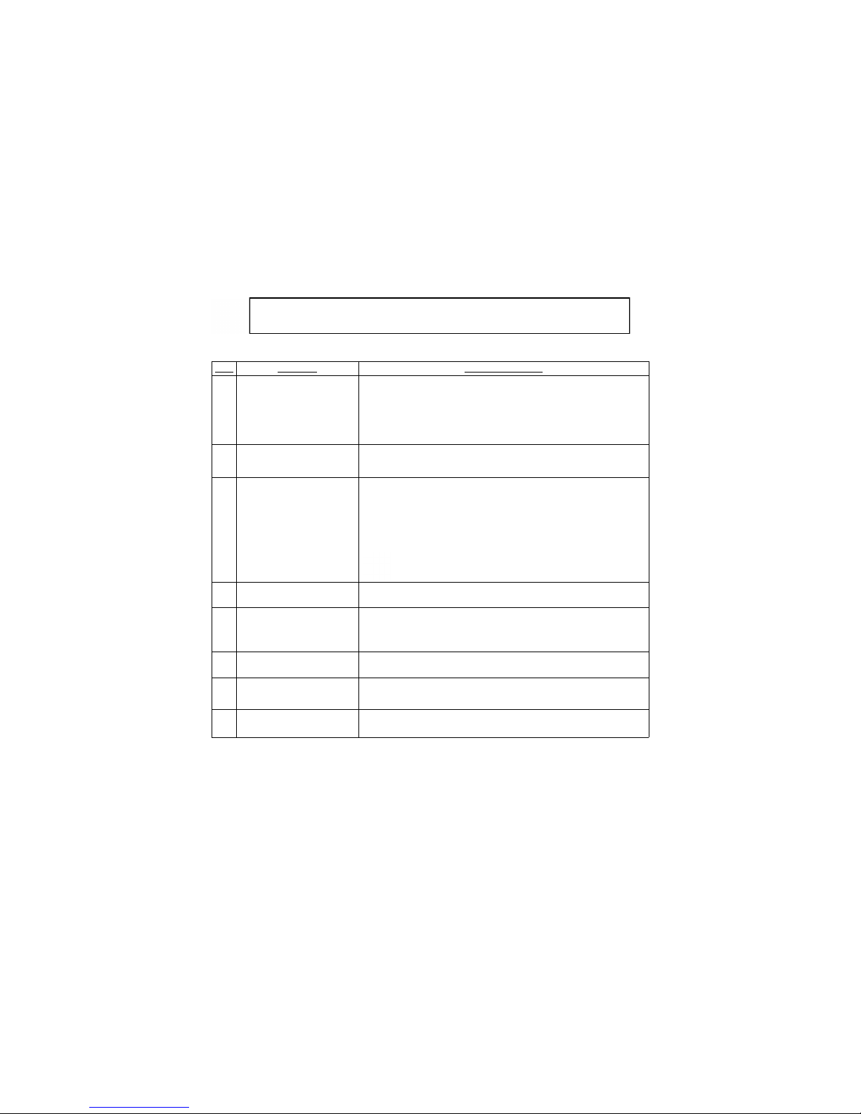
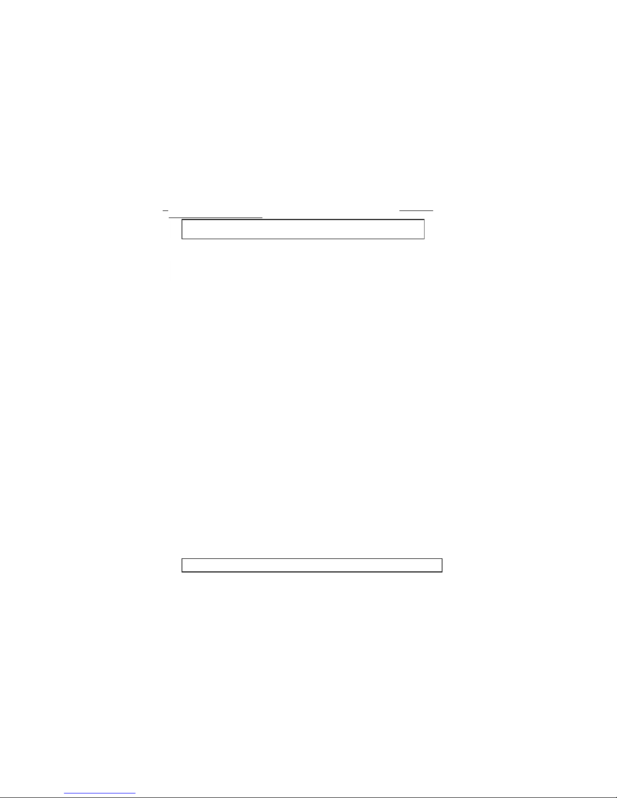
F. TEST START-UP
To test operate an Ultrafryer gas fryer equipped with an Ultrastat 23 Cooking computer:
1. Ensure the fryer‟s On/Off switch is in the OFF position.
2. Ensure the fryer vat is filled with hot or cold water to the middle of the “E” in the word LEVEL on the rear of the vat.
3. Turn the MANUAL gas valve to the OFF position and wait FIVE (5) minutes for any accumulated gas to disperse.
4. ENSURE the MAIN gas shut-off valve is in the ON position and that the Vent Hood EXHAUST FAN is ON.
5. Turn the MANUAL gas valve to the ON position.
6. Perform the following steps, in the order listed:
STEP ACTION RESPONSE
1 Ensure the drain valve lever is in the closed position
and that water is at the proper level; then turn the On/
Off switch to the ON position.
The AMBER power lamp beside the fryer On/Off switch will illuminate.
Spark will light pilot flame.
2 Turn the computer ON by depressing the computer
On/Off button; then place the computer in the BOIL
mode by pressing the P key scroll to boil press P key
again to activate.
A. BOIL will appear in the computer display.
B. The HEAT lamp on the computer and the RED burner indicator lamp on
the fryer will cycle ON and OFF to heat the water to 190˚F (88˚C)
3
When the water reaches temp 190 F (87.8 C), the
heat light will go off. To Exit, Press the on/off
button.
A. Boil appears in the display heat indicator light goes off.
B. OFF appears in the display.
4 Turn the computer OFF by depressing it‟s On/Off
button then turn the on/off toggle switch to the OFF
position.
A. The computer display will go BLANK.
B. The AMBER power lamp will extinguish.
5 After the water in the vat and the fryer metal surfaces
have COOLED drain the water into a floor drain.
CAUTION: PRIOR TO PROCEDING TO STEP 1, VISUALLY CHECK THAT THE HEAT EXCHANGER TUBES ARE COV-
ERED BY AT LEAST 2” (51MM) OF WATER.
Page 11
30A134
Shortening Level
Mark
Fryer On/Off Switch
Main Gas Valve
Manual Gas Valve
Page 19

A. GENERAL
This gas fryer is equipped with a shortening filter system which is to be operated and cleaned according to the FRYER
OPERATION and CLEANING sections of this manual.
1. SHORTENING
Use a high quality shortening to achieve a consistent quality product as well as a long term savings.
2. SHORTENING TEMPERATURE
Most products should be cooked with a shortening temperature about 350˚F (177˚C); however, each product should be
cooked at the LOWEST temperature that produces a high quality product while obtaining maximum usage of the shortening.
3. SALTING
Products should not be salted over the fryer vessel as salt quickly deteriorates the shortening and flavors other products
cooked in the same shortening.
4. POWER FAILURES
The fryer cannot be operated during power failures. DO NOT attempt to manually operate the fryer.
5. PUMP MOTOR
The filter pump motor is protected by a motor thermal overload switch.
B. FILTERING SHORTENING
Fryer‟s equipped with a stainless steel filter screen should be filtered at least twice a day. Place the recommended amount of
filter agent in the shortening as prescribed by the chemical supplier and follow instructions for filtering shortening provided
in the operating section of this manual.
C. LEVELING SHORTENING (TOPPING OFF)
After filtering, the shortening level must be checked and fresh shortening added when necessary.
1. The shortening in the vat should reach to the middle line of the “E” in the word LEVEL of the shortening level mark on the
rear wall of the fryer.
2. If shortening is needed, Add a small amount to bring shortening to the proper level.
3. Repeat the above steps until the shortening in the vat is at the proper level.
D. BOILING OUT FRYER
The fryer should be BOILED OUT every 7 DAYS to remove carbon buildup and other encrusted materials. Add the amount
of boil out compound to the fryer as prescribed in the cleaning manual provided by the chemical supplier and follow instructions for boiling out a fryer in the operating section of this manual.
E. CLOSING / SHUTDOWN INSTRUCTIONS
1. CLOSING
When closing at night; filter the shortening in the fryer, THOROUGHLY drain all filter lines and cover the fryer vessel.
Turn the ON/OFF Switch on the fryer OFF and turn the Manual Gas Valve OFF.
2. SHUTDOWN OR PROLONGED POWER FAILURE:
a. Shutdown
Perform the following whenever a fryer is being shutdown for an extended period of time:
1. Drain and discard the shortening.
2. THOROUGHLY clean the fryer vat.
3. Turn the ON/OFF Switch to the OFF position, disconnect the 230-volt power cord and turn applicable Circuit
Breakers OFF.
4. Turn the Manual Gas Valve OFF.
b. Prolonged power failure
The gas fryer cannot be operated during power failures. DO NOT attempt to bypass safety controls and manually start
the fryer.
WARNING: ENSURE THE WASH DOWN HOSE IS NOT CONNECTED TO FRYER PRIOR TO
RESETTING A THERMAL OVERLOAD SWITCH.
Page 12
30A134
ABBREVIATED OPERATING INSTRUCTIONS
CAUTION: THE GAS FRYER CANNOT BE OPERATED DURING POWER FAILURES. DO
NOT ATTEMPT TO
Page 20
A. PREVENTIVE MAINTENANCE
Minimal maintenance is required on a gas fryer because of its design and the materials used in the manufacturing process.
However, some preventive maintenance and inspection must be performed periodically to prevent break downs which could
curtail food sales. Any preventive maintenance or inspection should be accomplished with CAUTION while the fryer is in
operation since HOT liquid shortening could cause severe burns. If service or repair is required, all gas and electric power
MUST BE TURNED OFF PRIOR TO performing that service or repair.
PREVENTIVE MAINTENANCE SCHEDULE
B. TROUBLESHOOTING
I. GENERAL
The problems and possible solutions listed in the troubleshooting chart below are typical problems that are
frequently encountered. ONLY qualified repairmen are to use the troubleshooting chart to repair this fryer. In
the event a main burner malfunction occurs, perform the following checks PRIOR to contacting a repairman:
a. Ensure Gas Valves are in their proper position.
b. Check that the fryer electrical plug is connected to an electrical receptacle.
c. Ensure the applicable Circuit Breaker is in the ON position and that the fryer ON/OFF switch is in the ON
position.
d. Ensure the applicable fryer control has been placed in the FULL ON mode.
e. Ensure the gas supply line quick-disconnect coupling is SEATED on the gas manifold fitting.
f. Determine that the blower is operating.
INSPECTION ITEM INSPECTION PRIORITY INSPECTION DESCRIPTION
Venthood Grease Filters DAILY Clean grease filters in the exhaust vent
hood each evening and allow them to dry
overnight.
Filter Tub DAILY Thoroughly clean the filter tub assembly
prior to leaving the store at closing
Drain Valve & Shortening Return Levers WEEKLY Determine that all levers are securely
attached and that they can be easily
opened and closed.
Temperature Sensing Probes WEEKLY During Boil-Out of the fryer inspect the
temperature and high limit sensing probes
for any visual damage
WARNING: CRUMBS AND SLUDGE LEFT IN THE FILTER TUB OVERNIGHT ARE A FIRE
HAZARD. THEY MUST BE DISCARDED AT THE END OF EACH DAY.
Page 13
30A134
PREVENTIVE MAINTENANCE & TROUBLESHOOTING
Page 21
2. TROUBLESHOOTING CHART
Should a problem occur that cannot be corrected after performing the above CHECKS, contact an AUTHORIZED repairman
and/or Ultrafryer Systems Customer Service (1-800-525-8130) and provide the information acquired while performing these
checks.
TROUBLESHOOTING CHART
WARNING: ENSURE REPAIRMEN ARE ADVISED THAT FRYER RESTRAINTS MUST BE DISCONNECTED/
CONNECTED IF A FRYER IS TO BE MOVED DURING MAINTENANCE OR REPAIR, AND THAT ELECTRICAL
POWER AND GAS MUST BE TURNED OFF PRIOR TO PERFORMING ANY MAINTENANCE OR REPAIR.
ITEM PROBLEMS POSSIBLE SOLUTIONS
1 Main burner will not ignite. Blower is
operating; but gas is not present at the
burner.
A. Check the Blower air pressure Switch by temporarily disconnecting the two (2) ORANGE
air switch wires and connecting them together. If the IGNITOR sparks when these wires
are connected, the air pressure switch is defective and it will have to be replaced.
B. Check the following components and replace if found to be defective:
Gas Control Valve
Hi-Limit Switch
Transformer
2 Electrical power is present at the fryer
but the Blower is not operating.
A. Blower may have over-heated and shut off on thermal overload. If this situation did occur,
it will correct itself when the motor cools (10-20 minutes). If this overheating problem
persists, replace the blower.
3 Excessive time is required to raise the
shortening to cooking temperature.
Temperature recovery is slow and
main burner flames are small and
appear to be lethargic.
A. Ensure that the MANUAL GAS VALVE is completely open.
B. Check for an obstruction in the gas line.
C. Check for an obstruction in the flue pipe.
D. Check that the ORFICE PLUG has the correct drill size opening as indicated on the table
on page 6.
E. Check for BLOWER damage.
F. Use a standard water-type U-gauge Manometoer to check the pressure at the gas control
valve pressure tap. Proper gas pressure is indicated on the table on page 4a-4c.
NOTE: If necessary remove the Pressure Regulator Adjustment Cover and adjust
this control to the burner and COUNTER CLOCKWISE to decrease gas
pressure. Replace adjustment cover.)
4 Shortening temperature is too high
and breaks down quickly.
A. Check the gas pressure as described above.
5 The filter pump motor fails to operate
when the Vat Shortening Return /
Topside Shortening Lever is placed in
the OPEN position.
A. Insure the filter pump micro-switch is good then check the manual reset button on the
filter pump motor.
B. If the filter pump motor fails to operate after the reset button has been depressed, repair
or replace the motor.
6 Decreased shortening flow rate while
filtering.
A. Check for excessive sediment on the filter screen standpipe suction fitting or in filter tub.
7 Pump/Motor operates but does not
pump shortenings.
A. Check for congealed shortening in the shortening system.
B. Check 11mm Bulkhead connection (STAUBLI).
8 Pump / Motor hums but will not pump
shortening
A. Check for congealed shortening in the pump or in shortening plumbing.
Page 14
30A134
Page 22
GENERAL
Any item of equipment operates better and lasts longer when it is kept clean and properly maintained and this Gas Fryer is no
exception. In order for the fryer to provide years of trouble-free service, it must be CLEANED and MAINTAINED according
to instructions herein and at the intervals listed below:
I. DAILY
A. Clean the fryer surface periodically during operating hours with a solution of sanitizer and hot water, and at closing with
stainless steel cleaner. If necessary, use a dampened 3M type 7447 RED or 7440 BROWN (heavy duty) Scotch Brite pad
to remove encrusted material.
Filter Tub
Latch
Filter Tub
Cover
CAUTION: TO ASSURE PRODUCING A QUALITY PRODUCT WHILE PROLONGING THE LIFE EXPECTANCY OF
THE FRYER, ENSURE FILTERING, BOIL-OUT AND CLEANING INSTRUCTIONS ARE STRICTLY ADHERED TO.
WARNING: DO NOT ALLOW ANY CLEANING SOLUTION OR WATER TO SPLASH INTO A VESSEL OF HOT
COOKING OIL, AS IT WILL CONTAMINATE THE OIL AND MAY CAUSE THE OIL TO SPLATTER
CAUSING SEVERE BURNS.
WARNING: CRUMBS AND SLUDGE LEFT IN THE FILTER TUB OVERNIGHT ARE A FIRE HAZARD
B. The Filter Tub Assembly and Filter Screen should be
cleaned EACH DAY after FILTERING and AT CLOSING and THOROUGHLY cleaned once each week to
remove the Filter Tub Assembly from the fryer:
● OPEN the Fryer‟s Service Access Door.
● DEPRESS the DOCKING RELEASE HANDLE,
shown above.
● PULL the Filter Tub Assembly from the fryer using
the Standpipe Docking Handle Assy.
Vat Shortening Return
Lever (shown Closed)
Topside Shortening Return
Lever (shown Open)
Docking Release Handle
Drain Valve
Page 15
30A134
CLEANING
Crumb Catcher Screen Standpipe Docking Handle Assy
CAUTION: DO NOT use steel wool, abrasive cloths, cleaners, powders or metal devices to scrape stainless
steel! Scratches on stainless steel are almost impossible to remove!
Page 23

C. CLEANING THE FILTER TUB AFTER FILTERING & AT CLOSING AS FOLLOWS:
1. Disassemble the Filter tub by removing the following items in the order listed; 1) FILTER TUB COVER, 2) CRUMB
CATCHER SCREEN, 3) FILTER SCREEN W/STANDPIPE/DOCKING attached; then 4) separate the STANDPIPE and
DOCKING ASSEMBLY from the Filter Screen.
2. Clean the Wash Down Hose with sanitizer solution; then hang the Wash Down Hose in an upright position so shortening
can drain into a container.
3. Discard crumb fragments in the Crumb Catcher Pan and THOROUGHLY clean the pan with HOT water and let it air dry.
4. Raise the Filter Assembly with Standpipe and Docking Assembly attached, above the Filter Tub and let any sediment or
shortening drain into the tub; then separate the standpipe/docking assembly from the Filter Screen and clean the assembly
with sanitizer solution and wipe it dry with a lint free cloth. Remove any sediment and shortening in the Filter tub using a
scraper; then wipe the tub dry with paper towels.
D1. THOROUGHLY CLEAN THE FILTER ASSEMBLY FOLLOWS:
1. “Micro-Mesh” Stainless Steel Filter Screen
a. CAREFULLY remove any debris from the screen using a scraper.
b. Grasp the FINGER LOOP on FRAME A and adjacent FINGER LOOP on FRAME B, EVENLY pull the frames
apart; then HINGE FRAME A to remove it from the FILTER SCREENS FIRST.
c. Grasp the FINGER LOOP on the straight side of FRAME B; then HINGE it to remove FRAME B from the
FILTER SCREENS.
d. Separate the UPPER FILTER SCREEN and BAFFLE from the LOWER FILTER SCREEN.
e. CAREFULLY clean the two frames, screens and baffle in the 3 compartment sink with hot water and allow these
items to air dry. DO NOT USE SOAP. If necessary the channels in each frame can be cleaned with the edge of a
scotch-brite pad.
f. Insert the SUCTION FITTING on the BAFFLE in the hole of the UPPER FILTER SCREEN; then place these items
on top of the LOWER FILTER SCREEN.
g. ENSURE all sides of the FILTER SCREEN assembly are aligned, place the PIN end of FRAME A on the FILTER
SCREENS, place the CHANNEL on the frame adjacent to the PIN end over the FILTER SCREENS; then HINGE the
frame so the edge of the FILTER SCREENS are inserted in the other CHANNEL of FRAME A.
h. Place the PIN end of FRAME B on the FILTER SCREENS so the PIN is seated in the CHANNEL of FRAME A
near the FINGER LOOP, place the CHANNEL on the frame adjacent to the PIN end over the edge of the FILTER
SCREENS; then HINGE the frame so the edge of the FILTER SCREENS are inserted in the other CHANNEL of
FRAME B and the PIN of FRAME A is seated in the CHANNEL of FRAME B.
i. Adjust FRAME A and B so both PINS are properly seated in the CHANNEL of the opposite frame; then CARE-
FULLY connect the KNURL KNOB on the STANDPIPE/DOCKING ASSEMBLY to the SUCTION FITTING on
the FILTER SCREEN assembly. DO NOT OVERTIGHTEN!!!
NOTE: Optional Magnepad
Filter Pad not shown
Page 16
30A134
Page 24

D2. OPTIONAL MAGNA PAD
1. If applicable, clean the Magnepad envelope filter pad at CLOSING as follows: Remove and discard the used filter pad
envelope, carefully clean the baffle assembly and clip/standpipe assembly in a 3 compartment sink with hot water and
allow these items to air dry. DO NOT USE SOAP!! Reassemble the Magnepad envelope filter using a NEW Magnesol
Impregnated Filter Pad or paper envelope as follows:
a. Insert the BAFFLE into the FILTER PAD ENVELOPE, when properly inserted, the SUCTION FITTING will pro-
trude through the hole in the pad.
b. Fold the FLAP over (in the direction of the hole) securing the Baffle inside the FILTER PAD ENVELOPE.
c. CAREFULLY align the CLIP & STANDPIPE ASSEMBLY so that the clip can secure the FLAP and the envelope
and the STANDPIPE will align over the SUCTION FITTING protruding through the envelope.
d. Tighten the knurled NUT on the STANDPIPE to the SUCTION FITTING protruding through the envelope.
e. Repeat DAILY steps 1 a through 1 d .
E. REASSEMBLE
1. CAREFULLY insert the assembled Filter Screen in the bottom of the Filter Tub; then CAREFULLY insert the Crumb
Catcher Pan in the Filter Tub with the DRAIN VALVE Docking Flange over the leading edge of the pan.
2. CAREFULLY position the FILTER TUB COVER on the OPEN end of the Filter Tub with the SLOT on the cover seated
around the Standpipe Handle Docking Assembly. Then, SECURE the cover to the standpipe assembly by locking the
latch on the cover.
3. Position the ASSEMBLED Filter Tub in front of the FILTER TUB GUIDES beneath the fryer; then CAREFULLY and
SLOWLY insert the Filter Tub into the fryer using the Standpipe Docking Handle until the MALE In Line Plug on the
Standpipe Docking Handle Assembly seats in the FEMALE Bulkhead Coupling adjacent to the Drain Valve Assembly
II. WEEKLY
A. Perform daily cleaning steps B through D.
B. Boilout fryer. If using mesh screen place the upper and lower FILTER SCREENS in the fryer with BOIL-OUT SOLU-
TION for cleaning. BOIL-OUT the fryer vat according to instructions contained in the cleaning manual provided by your
chemical supplier.
C. After the filter screens have been cleaned in the Boil-Out Solution, ENSURE they are THOROUGHLY sprayed with a
solution of 1 PART vinegar to 25 PARTS of water to NEUTRALIZE the boil-out solution, then allow the screens to air
dry. NOTE: any residue of boil-out solution on the filter screens could cause the rapid break-down of the shortening.
D. Reassemble the “Micro-Mesh stainless steel filter according to DAILY steps D1f through D1.
E. Place the CRUMB CATCHER PAN and SLUDGE CATCHER SCREEN in the fryer with the Boil-Out Solution for
cleaning, and after they are cleaned, ENSURE they are sprayed with a solution of vinegar/water as described in
WEEKLY above.
F. THROUGHLY clean the Filter Tub, Cover and Sludge Catcher Pan with HOT SANITIZER SOLUTION and allow them
to air dry.
G. Re-assemble and install the Filter Tub according to the FILTER TUB ASSEMBLY AND INSTALLATION section of
this manual.
CAUTION: WHEN ASSEMBLED, ENSURE THERE ARE NO FINGER LOOPS ON THE STANDPIPE SIDE OF THE
FILTER.
Page 17
30A134
CAUTION: DO NOT PLACE THE BAFFLE OR STANDPIPE IN THIS SOLUTION!!!
Page 25

A. GENERAL
The Model PAR-3-14HE CE gas fryer is equipped with an Ultrastat 23 Cooking computer. Mounted on the fryer‟s Tem-
perature control panel are the following: fryer ON/OFF switch, AMBER Power indicator lamp and RED Burner indicator
lamp. The Electric and Manual Gas valves, Ignitor Rod and Module as well as the High-Limit Temperature switch are located behind the Service Access door. The Hard Docking Filtration system and Drain levers are also located behind the
service access door.
PAR-3-14HE CE GAS FRYER
CONTROL PANEL
Ultrastat 23 Computer
Controller Access
Door
Red Burner Indicator Lamp Fryer On/Off Power Switch
Amber Power Indication Lamp
Page 18
30A134
FRYER OPERATION
Page 26

B. ULTRASTAT 23 COOKING COMPUTER
The Ultrastat 23 Cooking Computer is connected to the fryer‟s electrical system to serve as its thermostat as well as provid-
ing heat control, status information and product cook timer. When the computer is in operation it will DISABLE the fryer if
the drain valve is OPENED.
This cooking computer is capable of cooking up to ten (10) different products; each of which can be programmed to be
cooked from one (1) to ten (10) different temperature at different times in a cook cycle. In addition, the operator can program
the ULTRASTAT 23 computer to cook products under “FLEX” or “STRAIGHT” timing modes. When programmed for
“FLEX” time mode the computer will adjust the actual cook time taking into consideration the temperature variation due to
load size, initial product temperature, product moisture content, and other factors that affect the cook cycle. Under
“STRAIGHT” time mode, the product is cooked at a specified temperature for the length of time programmed without adjust-
ing for these variations. Operation of the ULTRASTAT 23 cooking computer is covered in the Computer Instructions
Manual PN 30A216 provided with the fryer.
Page 19
30A134
Page 27

C. COMPUTER PANEL KEY DESCRIPTIONS
1. HOLD LAMP
When lit (bright) indicates a product hold time is being tracked.
2. HEAT LAMP
When lit (bright) indicates the computer is calling for heat.
3. DISPLAY
Displays modes, functions and operations of the computer.
4. MELT LAMP
When lit (bright) indicates the computer is in the melt cycle.
5. PROGRAM LAMP
When lit (bright) indicates the computer is in the program mode.
6. ON/OFF KEY
Turns the computer ON and OFF when the fryer power switch is in the ON position and the drain valve lever is in the
closed UP position.
7. PROGRAM KEY
a. In “operating” mode, allows access to the programming mode.
b. In “programming” mode, allows access to the operating mode and general navigation function see page 20.
8. SCAN KEY
a. In “operating” mode, displays the remaining cook time on every product currently in a cook cycle and lights the re-
spective products “LED” for 2 seconds.
b. In “programming” mode, steps to the next function to be programmed.
9. ENTER EXIT FILTER KEY
This key will force a filter the fryer into the filter mode. This key is an optional feature.
10. TEMP/TOGGLE CLEAR KEY
a. In “operating” mode, displays the actual temperature followed by the programmed “set” temperature.
b. In “programming” mode, allows the user to “toggle” (switch) between choices in an entry field and “clear” values
from a data field.
11. HOLD KEY
a. In “operating” mode, used to view remaining hold times.
12. SET BACK
a. In operating mode forces setback . Display will show “setback” and appliance will be controlled to setback tempera-
ture instead of setpoint temperature.
13. EXIT/MELT KEY
a. In “operating” mode, used to manually exit the shortening melt cycle.
b. In “programming” mode, used to enter numerical value 0.
14. PRODUCT LED
a. When lit (bright) in the “operating” mode, identifies the product data being displayed.
b. When lit (bright) in the “programming” mode, identifies the product being programmed.
15. PROGRAMMING AND PRODUCT COOK KEY
a. In “operating” mode, used to start and stop a product‟s cook cycle.
b. In “programming” mode, used to enter numerical values 1 to 10.
12 11
10 9
8
7
6
1 2 3 4
5
15
14
Page 20
30A134
Menu Strip
13
Page 28

D. DISPLAY DESCRIPTIONS
30A134
Page 21
Page 29

E. ULTRASTAT 23 START-UP AND COOKING COMPUTER OPERATION
NOTES: 1) The computer will keep the fryer in the MELT CYCLE until the EXIT MELT button is manually de-
pressed.
2) The computer CANNOT be taken out of the SHORTENING MELT MODE until the shortening temperature reaches the MELT LIMIT TEMPERATURE. The Melt Limit Temperature is factory set for a
HIGH exit temperature (135˚F / 57˚C) or a LOW exit temperature (100F).
The following are abbreviated operating procedures for a fryer equipped with an Ultrastat 23 Cooking Computer. The attached Ultrastat 23 Ultrafryer Computer Operating Instructions, Manual PN 30A216, contains DETAILED Operating, Filtering, Boil-Out and Programming Instructions.
1. START-UP and COOKING
Safely start-up a gas fryer equipped with an Ultrastat 23 Cooking computer as follows:
1. ULTRASTAT 23 START-UP - Safely start-up a gas fryer equipped with an Ultrastat 23 Cooking computer as follows:
2.
F. ULTRASTAT 23 COOKING COMPUTER PROGRAMING
Program the Ultrastat 23 Cooking Computer according to the, Computer Operating Instructions Manual, (PN 30A216)
provided with the Fryer.
NOTE: PROGRAMMING OF AN ULTRASTAT 23 COOKING COMPUTER SHOULD ONLY BE PERFORMED
BY A STORE MANAGER OR AREA SUPERVISOR.
Page 22
30A134
2 Turn the Computer ON by depressing the
computer ON/OFF button.
A. The MELT lamp will LIGHT to indicate the computer is in the
SHORTENING MELT MODE.
B. The HEAT lamp on the computer and the RED heat mechanism indi-
cator lamp on the fryer will cycle ON and OFF indicating the heat
mechanism is periodically being turned ON and OFF to gently heat
the shortening.
3 Once the Melt Limit Temperature is
reached depress the EXIT MELT BUTTON on the computer to cancel the
SHORTENING MELT MODE.
A. LO will appear in the computer display indicating shortening tem-
perature is more than 10˚F (5˚C) below the set-point temperature.
B. The HEAT lamp on the computer and the RED heat mechanism
indicator lamp will remain ON until the set-point temperature is
reached.
4 When “Ready” appears in the Computer
display indicating the SET-POINT TEMPERATURE of the shortening has been
reached, a COOK cycle can be initiated.
A. Stir the shortening several times to ensure that all the shortening has
reached the set point temperature.
CAUTION: PRIOR TO PROCEEDING TO STEP 2 VISUALLY CHECK THAT THE HEAT EXCHANGER
IS COVERED WITH AT LEAST 2" (51 mm) OF SHORTENING AND THE PILOT FLAME IS
LIT.
STEP ACTION RESPONSE
1 ENSURE the drain valve lever on the fryer
is in the CLOSED position, shortening is at
the proper level, then turn the fryer ON/OFF
switch to the on position.
A. The AMBER Power lamp beside the ON/OFF switch will
LIGHT.
B. The ignitor module will turn on and ignite the pilot flame.
Page 30

A. GENERAL COOKING
Most products should be cooked with a shortening temperature about 350˚F (177˚C); however, each product should be
cooked at the LOWEST temperature that produces a high quality product while obtaining maximum usage of the
shortening.
I – DO USE A HIGH QUALITY SHORTENING TO ACHIEVE A CONSISTENT QUALITY PRODUCT AND
LONG TERM SAVINGS
II – DO NOT SALT PRODUCTS OVER THE FRYER AS SALT QUICKLY DETERIORATES THE SHORTEN
ING AND FLAVORS OTHER PRODUCTS COOKED IN THE SAME SHORTENING
III – DO FILTER SHORTENING AFTER THE LUNCH AND DINNER RUSH AND MORE OFTEN IN A HIGH
SALE VOLUME STORE; AND BOIL-OUT THE FRYER EVERY 7 DAYS
NOTE: Startup steps 1, 2, 3, and 4 will have to be repeated each time any of the following occurs:
DRAIN VALVE IS OPEN. FRYER TOGGLE ON/OFF SWITCH IS T URNED OFF TO FILTER
SHORTENING OR BOIL-OUT A FRYER. FRYER TOGGLE ON/OFF SWITCH IS TURNED
OFF AT CLOSING OR ANY OTHER REASON.
When the Computer is taken out of the SHORTENING MELT MODE each morning, shortening in the fryer vat will be
heated to its SETPOINT temperature HEATING will appear in the display to indicate the shortening temperature is
MORE than 20˚F (-6.6˚C) BELOW the setpoint temperature. When shortening temperature rises to the SETPOINT temperature, “READY” will appear in the display indicating a COOK CYCLE can be started.
B. STARTING A COOK CYCLE
To start a cook cycle simply press the product key for the () product you wish to cook. If the product is programmed, the
correct cooking time will be displayed “1200” (example) and this time will immediately start to count down in minutes and
seconds. If “DON’T” is displayed immediately and the unit starts to signal, the key being operated is not programmed. If
correctly programmed, it will count down “ :00” to followed by and start to signal. To turn this signal OFF and reset the
Computer, press the product key used to
start the COOK CYCLE.
C. CANCELLING A COOK CYCLE
If a cook cycle was inadvertently started it may be cancelled two (2) ways:
1) Press and hold the same product key () used to start the cook cycle for 4 SECONDS. This prevents an accidental start
of a cook cycle () while a product is being cooked.
2) A cook cycle can be CANCELLED at any time by turning the fryer ON/OFF Switch to the OFF position.
Press product key
Page 23
30A134
Page 31

A. FILTER TUB ASSEMBLY
ENSURE all components of the filter tub have been thoroughly cleaned and that the Filter Screen has been assembled ac-
cording to the CLEANING Section of this manual; then assemble the filter tub as follows:
1. Connect the KNURLED KNOB to the STANDPIPE
DOCKING HANDLE ASSEMBLY; then attach this assembly to the SUCTION FITTING on the Filter Screen. DO
NOT OVERTIGHTEN THIS CONNECTION!!!
2. Place the Filter Screen in the bottom of the Filter Tub with
the screen butted against the rear wall of the tub.
3. Insert the Crumb Catcher Screen in the Filter Tub with the
Drain Valve DOCKING FLANGE and MALE DOCKING
PLUG over the leading edge of the pan.
4. Position the FILTER TUB COVER on the open end of the
Filter Tub with the SLOT on the cover seated around the
Standpipe Docking Handle Assembly. Then, SECURE the
cover to the standpipe assembly by locking the latch on the
cover.
B. FILTER TUB INSTALLATION
Position the ASSEMBLED Filter Tub in front of the FILTER
TUB GUIDES beneath the fryer; then CAREFULLY insert
the Filter Tub into the fryer using the standpipe handle assembly until the MALE In-Line Plug on the Docking Handle Assembly
seats in the FEMALE Bulkhead Socket adjacent to the Drain Valve
Assembly.
WARNING!! CRUMBS AND SLUDGE LEFT IN THE FILTER TUB OVERNIGHT ARE A FIRE HAZARD!!
Filter Tub
Filter Tub Guides
Docking Release Handle
Hard Docking Connection
Page 24
30A134
FILTER TUB ASSEMBLY & INSTALLATION
Page 32
A. FILTERING SHORTENING
1. Turn the ON / OFF SWITCH on the fryer to OFF, turn the MANUAL GAS VALVE OFF, and ensure the filter tub is
properly docked beneath the drain valve.
NOTE: Pull on the filter tub Handle to ASSURE the male docking plug is SEATED in the female bulkhead socket.
2.Place the amount of FILTER AGENT into the fryer vat as prescribed in the cleaning manual provided by your chemical
supplier; thoroughly stir the filter agent into the shortening using a skimmer; then skim the shortening to remove any floating crumbs.
3. Carefully attach the drain valve handle to the drain valve; then open the drain valve by turning the DRAIN VALVE HANDLE slightly downward. When the bottom of the filter tub is covered with about two (2) inches of shortening, completely
OPEN the drain valve, and while shortening is draining, scrape all sides of the vat to remove encrusted material using the
scraper.
4. When all shortening has drained into the filter tub, use the DRAIN ROD to stand the wire rack on one side of the vat.
5. Use the drain rod to pull the sediment on the bottom of the vat towards the valve opening, then use the rod to push sediment through the valve opening.
6. If there is NO sediment or debris visible on the heat exchanger or bottom of the vat, CLOSE the drain valve; then turn the
LEFT HAND Vat Shortening Return Lever 1⁄4 turn counter clock wise to automatically return shortening in the filter tub
through the SWEEP NOZZLE in the bottom of the vat. When all shortening has been returned to the vat, turn the LEFT
HAND Vat Shortening Return Lever 1⁄4 turn clockwise to stop the flow of shortening.
7. If there is considerable sediment and debris on the bottom of the vat, FLUSH this sediment from vat using the Wash Down
Hose as follows:
a. Leave the drain valve in the OPEN position, CAREFULLY connect the Wash Down Hose Male In-Line Plug to the
TOPSIDE FEMALE SOCKET; then place the Wash Down Hose nozzle into vat and hold it firmly against an inner wall
so it will not recoil upward when the pump comes on.
b. Turn the RIGHT HAND Topside Shortening Return Lever 1⁄4 turn counter clock wise and hold the hose nozzle at 45˚
angle from the bottom of the vat causing sediment and debris to bounce off the rear wall and flow towards the drain
valve.
c. Use the “L” shaped brush to push the sediment through the drain valve to keep the drain clear. Hose off the heat ex-
changer and vat walls until all sediment and debris has been flushed through the drain into the filter tub.
CAUTION: PRIOR TO PROCEEDING TO THE NEXT STEP, PUT ON SAFETY GOGGLES, NEOPRENE
INSULATED GLOVES AND AN APRON.
CAUTION: DO NOT ACTIVATE (TURN) THE VAT SHORTENING RETURN LEVER AND TOPSIDE
SHORTENING LEVER AT THE SAME TIME! TO DO SO WILL REDUCE SHORTENING FLOW.
Vat Shortening Return
Lever (shown closed)
Topside Shortening Return Lever (shown open)
Drain Valve
Docking Release
Handle
Page 25
30A134
FILTERING AND POLISHING SHORTENING
Page 33

d. Turn the RIGHT HAND Topside Shortening Return Lever 1⁄4 turn counter clock wise; then CAREFULLY remove the
Wash Down Hose MALE In-Line Plug from the TOPSIDE FEMALE SOCKET by depressing the Topside Socket Release
Knob.
e. Hang the Wash Down Hose in an up-right position so shortening can drain into a metal container; then proceed to para-
graph B 1 below.
B. POLISHING SHORTENING
1. Set a timer for the amount of time established for POLISHING shortening, then turn the VAT SHORTENING RETURN
LEVER 1/4 TURN COUNTER CLOCKWISE to allow shortening to circulate through the system to POLISH the
shortening.
2. At the end of the established time, TURN the VAT SHORTENING RETURN LEVER 1/4 TURN CLOCKWISE, turn the
DRAIN VALVE HANDLE to the closed UP position; replace the grill in the fryer; then TURN the Vat Shortening RETURN LEVER 1/4 COUNTER CLOCKWISE to automatically return shortening in the filter tub to the fryer vat.
3. When all shortening in the filter tub has been returned to the fryer, TURN the VAT SHORTENING RETURN LEVER,
1/4 TURN CLOCKWISE check and if necessary add fresh shortening so shortening is level with the middle line of the
letter “E” in the word LEVEL of the shortening level mark on the rear wall of the fryer.
4. Remove the Filter Tub Assembly by pressing the DOCKING RELEASE HANDLE and pulling the STANDPIPE DOCKING HANDLE ASSY away from the FEMALE Bulkhead Socket adjacent to the Drain Valve; then THOROUGHLY
clean, assemble and replace the Filter Tub Assembly in the fryer cabinet.
(Basket Hanger Bracket Not Shown For Clarity)
Wash Down Hose
Guide
Topside Socket Release
Knob
Topside Female Socket
and Proximity Sensor
Switch
CAUTION: DO NOT POLISH THE SHORTENING MORE THAN THE ESTABLISHED TIME AS IT WILL
PUMP EXCESS AIR INTO THE SHORTENING CAUSING SHORTENING BREAKDOWN.
Page 26
30A134
Page 34
A. GENERAL
The gas fryer should be BOILED-OUT every 7 DAYS to remove carbon buildup and other encrusted material.
B. SHORTENING DISPOSAL
1. CAREFULLY assemble and install the Filter Tub assembly according to the instructions in the FILTER TUB
ASSEMBLY AND INSTALLATION section.
2. Turn the ON/OFF switch and Manual Gas Valve OFF, and ensure the filter tub is properly DOCKED beneath the fryer
drain valve.
NOTE: Pull on the filter tub to ASSURE the male docking plug is SEATED in the female bulk head socket.
3. Attach the Drain Valve Handle to the drain valve; then open the drain valve by turning the DRAIN VALVE HANDLE
slightly downward. When the bottom of the filter tub is covered with about two (2) inches of shortening, completely
OPEN the drain valve, and while shortening is draining, scrape all sides of the vat to remove encrusted material using a
scraper.
4. When all shortening has drained into the filter tub, use the DRAIN ROD to place the wire rack on one side of the vat.
5. Use the drain rod to pull sediment on the bottom of the vat towards the drain valve opening and push it through the valve
opening.
6. FLUSH sediment and debris from the fryer vat as follows:
a. CAREFULLY connect the Wash Down Hose MALE In-Line Plug to the TOPSIDE FEMALE SOCKET and place the
Wash Down Hose into the vat and hold it firmly against an inner wall so it will not “recoil” upward when the pump
comes ON.
b. TURN the Topside Shortening Return Lever 1/4 turn counter clockwise and hold the wand hose nozzle at a 45˚ angle
from the bottom of the fryer causing sediment and debris to bounce off the rear wall of the vat and flow towards the
drain valve.
c. Use the “L” shaped vat brush to push the sediment through the drain valve to keep the drain clear. Hose off the burner
tubes and all walls of the vat until all the sediment and residue at the bottom of the fryer has been flushed through the
drain into the filter tub. Then turn the Topside Shortening Return Lever 1/4 turn clockwise.
7. DISPOSE of the shortening in the filter tub as follows:
a. Restaurants NOT equipped with a Shortening Disposal System.
1) Place the Wash Down Hose NOZZLE into a METAL container and hold it firmly against an inner wall.
2) TURN the TOPSIDE SHORTENING RETURN LEVER 1/4 TURN COUNTER CLOCKWISE and pump shortening into the metal container.
3) When all shortening has been pumped into the container, TURN the TOPSIDE SHORTENING RETURN LEVER
1/4 TURN CLOCKWISE, remove the Wash Down Hose from the TOPSIDE FEMALE SOCKET and hang the hose
in an upright position so shortening in the hose can drain into a container.
b. Restaurants equipped with a Shortening Disposal System.
1) SECURELY connect the Shortening Disposal Hose fitting to the TOPSIDE FEMALE SOCKET and connect the
fitting on the other end of the hose to the Disposal System connector on the wall.
2) TURN the TOPSIDE SHORTENING RETURN LEVER 1/4 TURN COUNTER CLOCKWISE and pump shortening in the filter tub into the Exterior rendering tank.
3) When all shortening has been pumped into the rendering tank, TURN the APPLICABLE TOPSIDE SHORTENING
RETURN LEVER 1/4 TURN CLOCKWISE, remove the Disposal Hose from the TOPSIDE FEMALE SOCKET.
Hang the hose in an upright position so shortening in the hose can drain into a container.
8. THOROUGHLY clean and re-assemble the filter tub.
C. BOIL-OUT - Boil-out the gas fryer following the cleaning instructions in the Cleaning Manual provided by your approved
chemical supplier. The following are generic procedures:
CAUTION: PRIOR TO PROCEEDING TO THE NEXT STEP, PUT ON SAFETY GOGGLES,
NEOPRENE INSULATED GLOVES AND AN APRON.
CAUTION: ONLY USE A COMERCIAL GRADE “NON-CHLORINE” BOIL-OUT COMPOUND.
Page 27
30A134
SHORTENING DISPOSAL, BOIL-OUT, AND REFILL
Page 35

1) Ensure the Drain Valve handle is in the closed (UP) position, then add water to the fryer vat 1"(25mm) BELOW the mid-
dle line of the “E” in the word LEVEL on the rear wall of the vat.
2) Add the amount of BOIL-OUT COMPOUND to the fryer vat as specified in the Cleaning manual provided by the chemical supplier.
3) Turn the ON/OFF switch and Manual Gas valve for the fryer vat to the ON position; then depress the Computer ON/OFF
key to the ON position.
NOTE: The drain lever must be in the closed (UP) position to turn the computer ON.
4) Place the Computer in the BOIL MODE by pressing the following “P” key for 3 seconds “program” will be displayed.
Press the up or down arrow key until “Boil” is displayed. Then press “P” key again.
NOTE: “BOIL” will appear in the Computer display and the Computer will turn the heat mechanism ON and OFF to
gradually heat and maintain the boil-out solution to 190˚F (88˚C).
5) When the boil-out solution reaches 190˚F (88˚C) the timer is set for 30 minutes. Frequently scrub the sides, front and rear
of the fryer vat with a long handled scrub brush.
6) After the boil-out solution has „BOILED‟ for 30 minutes and the timer sounds, press and hold the “P” key for 3 seconds in
to EXIT BOIL MODE:
7) Turn the ON/OFF Switch and the Manual Gas Valve for the fryer to the OFF position and then CAREFULLY dispose of
the boil-out solution in the fryer into a floor drain.
8) Use a scrubbing pad to remove carbon buildup from the top of the heat mechanism. To remove carbon build-up on the
sides and bottom of the heat mechanism; slide one end of a stropping pad under each section, grasp that end with a pair of
tongs, and rock the pad up and down along the length of each section until all encrusted material has been removed.
9) Rinse the fryer with hot water until the water coming out of the drain valve is clear.
10) Mix a solution of ONE PART vinegar to 25 PARTS of water. Place this mixture into a one gallon garden pressure
sprayer; and THOROUGHLY spray this solution onto the SIDES, HEAT EXCHANGER, and BOTTOM of the fryer vat
to neutralize the Boil-Out Compound.
11) After the neutralizing solution has drained from the vat and the vat has been dried with a lint free cloth, turn the drain
valve to the CLOSED (UP) position.
D. SHORTENING REFILL
1. LIQUID SHORTENING
When using liquid shortening, fill the fryer with cool shortening 1/2"(13mm) BELOW the “E” in the word LEVEL. When
heated ensure the shortening level is even with the middle line of the “E” in the word LEVEL. Add shortening as needed.
2. SOLID SHORTENING:
a. Cut a block of solid shortening into small pieces.
b. Place small pieces of solid shortening EVENLY on top of the HEAT EXCHANGER TUBES or THOROUGHLY
PACK these pieces of solid shortening between, below and above the HEAT EXCHANGER TUBES. While packing
solid shortening is messy and time consuming, it is the safest and fastest way to melt solid shortening.
c. Continue adding solid shortening as follows:
1) Place small pieces of solid shortening into a fry basket.
2) CAREFULLY lower the basket into the fryer vat.
3) GENTLY turn the basket to allow these pieces of solid shortening to float away.
4) Repeat the above steps until liquid shortening is even with the middle line of the “E” in the word LEVEL of the
shortening level mark on the rear wall of the fryer vat.
WARNING: DO NOT USE THE FILTER PUMP TO REMOVE WATER FROM THE VATS AS THIS WILL
CAUSE PREMATURE PUMP FAILURE AND VOID THE PUMP WARRANTY.
NOTE: Boil-Out Compound will cause shortening to break down rapidly if it is not neutralized.
Page 28
30A134
WARNING: ENSURE THE VAT IS COMPLETELY DRY BEFORE ADDING AND HEATING NEW SHORTEN-
ING. HOT SHORTENING AND WATER CAN CAUSE AN EXPLOSIVE REACTION
Page 36

TECHNICAL ASSISTANCE - Contact an authorized service agent or the Customer Service Department, Ultrafryer
Systems at 1-800-525-8130 for technical assistance.
E-Mail technical assistance at: techserv@ultrafryer.com
B. ORDERING INFORMATION:
1. REPLACEMENT PARTS - Provide the following information when ordering replacement parts by phone, fax or mail:
Your company name and phone number
Your company purchase order number
Bill-to address
Ship-to address
Quantity desired
Part number and description of the desired-item Your name or signature of authorized-buyer
Phone in order to: 954-202-7336
FAX order to: 954-202-7337
Mail order to: Greenfield World Trade
U.S. Office
3355 Enterprise Ave. Suite 160
Ft Lauderdale, FL 33331
Website: www.Greenfieldworld.com
2. DAMAGES - Ultrafryer Systems is not responsible for damage occurring in transit. All deliveries must be inspected for
damage to shipping containers prior to departure of the delivering carrier. Any damage must be notated on the receiving
document to facilitate filing of freight claims. Carriers must be notified immediately and freight inspections must be requested from the carrier. Ultrafryer Systems can and will gladly assist you in preparing and processing of the necessary
claims only if proper notification has been accomplished on the carrier delivery document. Damaged equipment and or containers must be available for the claims inspector to inspect.
TECHNICAL ASSISTANCE, ORDERING INFORMATION
30A134
Page 29
Page 37
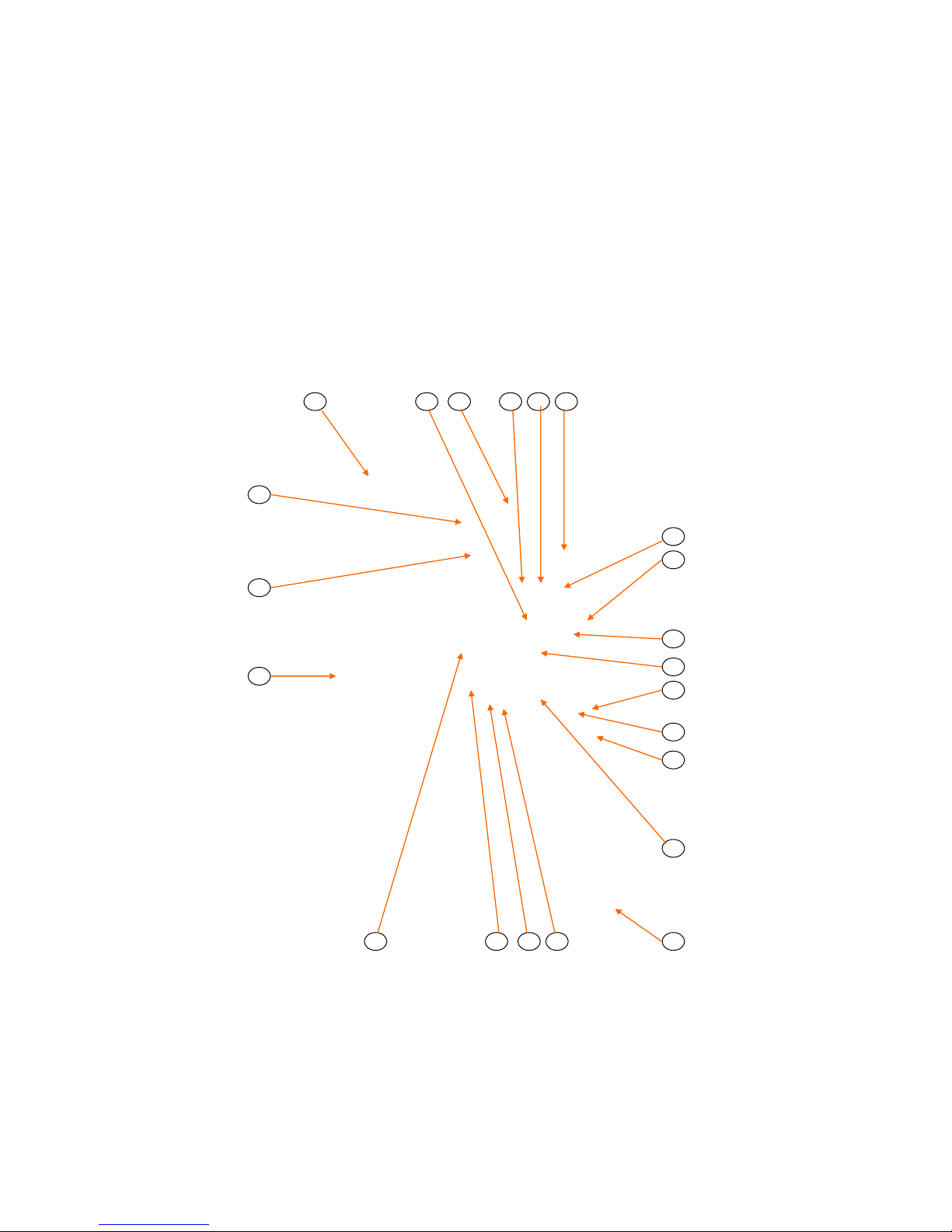
A. PARTS IDENTIFICATION
Locate the part on the following sketches and note the index number i.e, 3, 6, etc; then obtain the part number and description
for that index number on the page facing the sketches. Use that part number when ordering a replacement part.
ULTRAFRYER MODEL PAR-3-HE CE GAS FRYER
FRONT VIEW
Page 30
30A134
PARTS IDENTIFICATION
1 31 22 8 7 15
14
21
10
4
16
19
27
13
26 11 23 6
12
5
3
28
Page 38
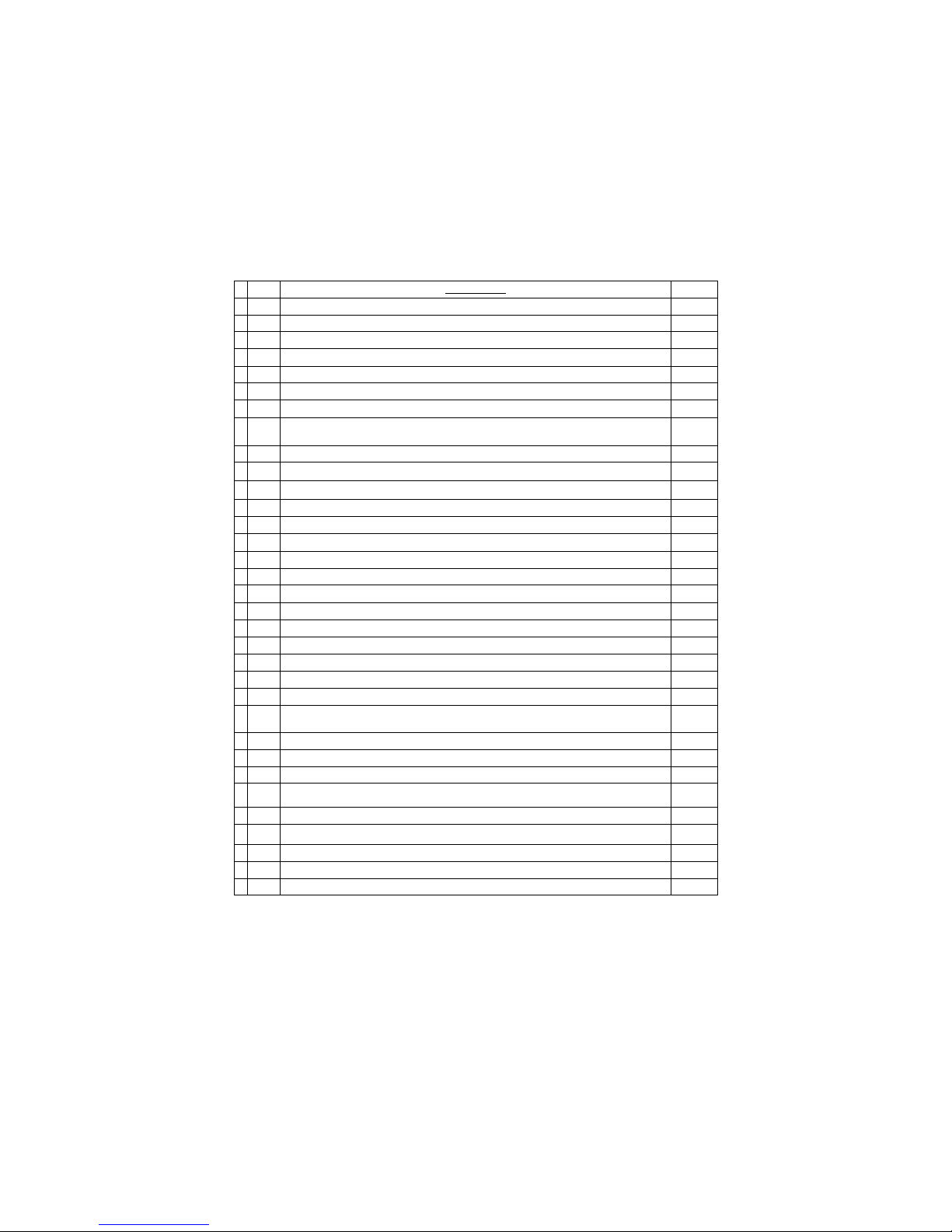
ITEM DESCRIPTION P/N
1 Computer, Cook FAST Meridian 22A436
* 2 14" Model PAR-3-H CE Vat Cover 12A500
3 Spark Ignitor Module 18A316
4 Drain and Filter Valve Lever Microswitch 18A064
5 Ignitor Rod Cable with 1/4 Stake-on Suppression Type 18A317
6 Electric Gas Combination Control Valve with Pilot Adjust Valve. 18A314
7 Probe, Temperature sensing Thermistor 18A006
8 Switch, Hi-Limit for Gas Fryer ((Order a 1⁄4" (5mm) Compression Fitting PN 24247 when ordering
this item.))
19A144
* 9 14" Model PAR-3-H CE Agitator Baffle Weldment 19A500
10 14" Model PAR-3-H CE Vat Shortening Return Lever 19B436
11 14" Model PAR-3-H CE Topside Shortening Return Lever 19B437
12 Drain Ball Valve Handle 19A558
13 Drain Ball Valve Assembly 19A564
14 Spark Ignitor Rod Assembly (Set Rod Gap to 5/32" (4mm) prior to installation) 12C196
15 Pilot light Heat Channel 19C271
16 Docking Release Handle 19A948
* 17 14" Model PAR-3-H CE F/F Basket Hanger Bracket 19A949
* 18 Chrome Door Pull 22005
19 Magnetic Door Catch 22407
* 20 14" Model PAR-3-H CE Fryer Vat Grill 22703
21 Ferrofix Nozzle Eclipse #GF-1 Burner 22A112
22 Cast Iron Venturi 22A118
23 1⁄2" (13mm) ID Manual Gas Valve 24326
* 24 Orifices Country
Specific
* 25 Orifice Plug Holder 24A105
26 1⁄2" (13mm) MIP x 1⁄2” (13mm) MIP Flexible Gas Line 18" (457mm) Long 24A138
27 1⁄2" (13mm) FPT S/S Female Bulkhead Coupling w/Raised Button Release 24A209
28 Medium Duty 3" (76mm) Front Caster w/Brake for all Model PAR-3-H CE Fryers. 28A010
* 29 Orifice, Pilot BCR-18 Natural Gas 18608
* 30 Orifice, Pilot BCR-12 Propane/Butane 18609
31 Tube, Siphon for Pilot Gas 19C398
* 32 “L” shape tip Cleaning Brush 29A044
* 33 Drain Clean-out Rod 12569
* NOT SHOWN
Page 31
30A134
Page 39
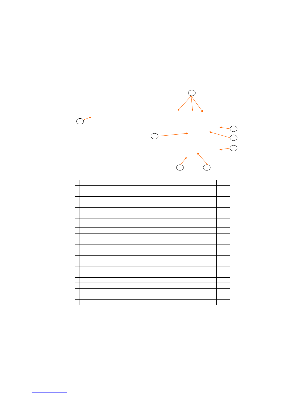
ITEM DESCRIPTION PN
1 1⁄2" (13mm) FPT S/S Female Bulkhead Coupling w/Raised Button Release 24A209
2 14" Model PAR-3-H CE 220 Volt 60 HZ Exhaust Blower Motor Kit w/Mounting Bracket 19A547
3 14" Model PAR-3-H CE Exhaust Blower Motor Gasket 19A545
4 Exhaust Blower Motor Drip Pan 19A527
5 3/16" (5mm) ID 5/16" (8mm) OD Air Pressure Switch Plastic Tube rated for 500˚ F (260˚C) 24A068
6 Air Pressure Switch 18A291
7 230/240 VAC 50/60 Mhz motor
5.5 GPM (19.25 LPM) pump
24A206
24329
8 14" Model PAR-3-H CE 53⁄4” x 8" High (146 x 208mm) Rectangular Flue Tube with deflector 19A910
* 9 Medium Duty 3" (76mm) Rear Caster w/out Brake 28A011
10 Electrical Box Assy 12C195
* 11 240 Volt 75 Watt Silicon Heater 5‟ (1524mm) Long 23401
* 12 1⁄2" (13mm) Pump Ball Valve 24-036
13 Rear Exit Weldment Baffle 19A463
14 240 Volt Surge Protector 18A063
15 Filter Circuit 12C191
16 Relay, Delay on Break 24 VAC 18A099
17 Relay, Delay on make 24 VAC 23A232
18 24 VAC DPDT Relay 18A076
19 24 VDC DPDT Relay 18A301
20 Transformer, Step Down 240 / 24 VAC 18A066
21 Thermostat, OOR SPST for Heater strip 18A315
* NOT SHOWN
ELECTICAL BOX PN 12C195
Page 32
30A134
ULTRAFRYER MODEL PAR 3-H FRYER REAR VIEW
21
19
18
20
16
15 14
17
Page 40
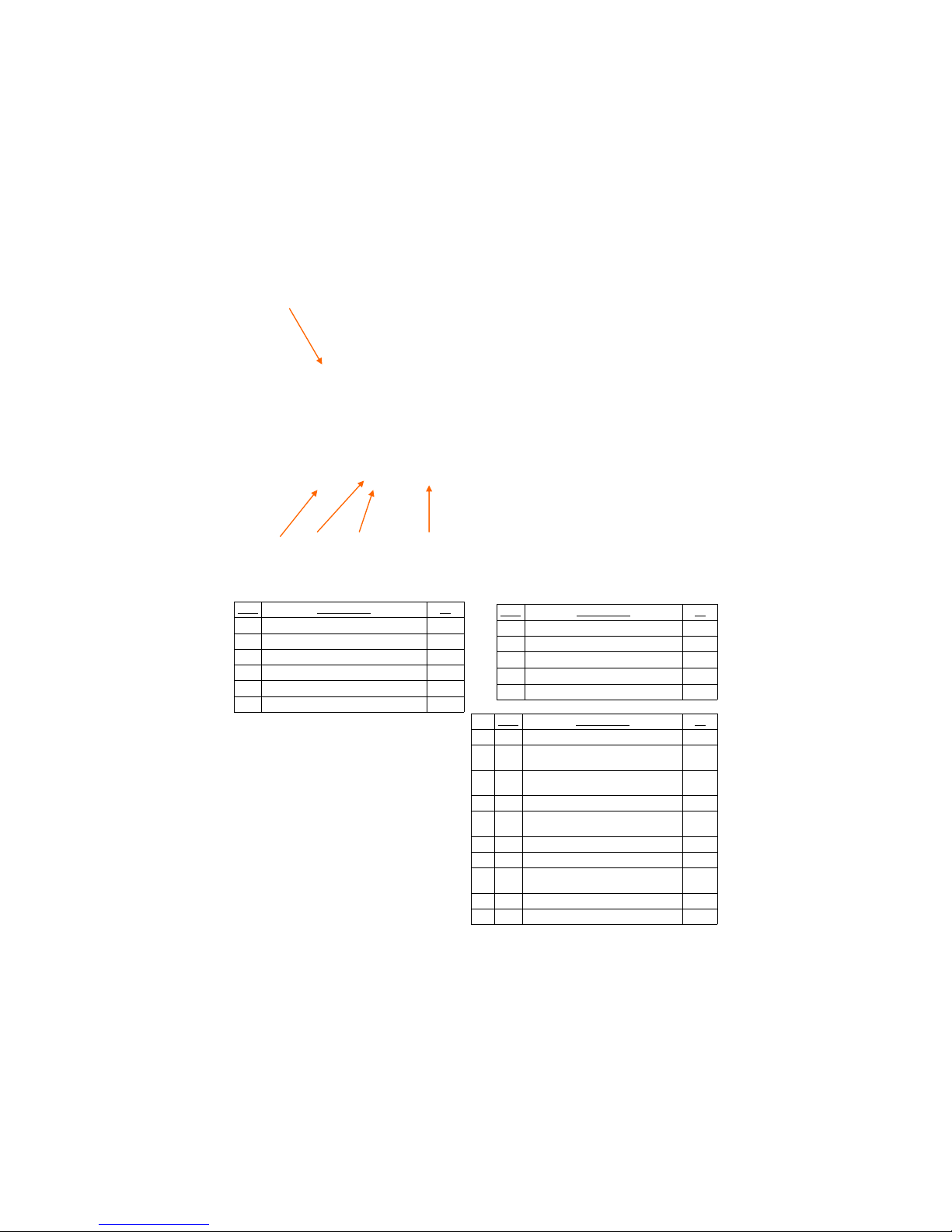
ITEM DESCRIPTION PN
1 On/Off Switch Guard. 18129
2 24 Volt 6 Amp SPDT ON/OFF Switch. 18A287
3 24 Volt 1/3 Watt Snaplight w/RED Lens. 23A103
4 ON/OFF Switch Protective Boot. 23402
5 24 Volt 1/3 Watt Snaplight w/AMBER Lens. 23A101
6 Ultrastat 23 Cooking Computer 22A436
ITEM DESCRIPTION PN
1 Micro-Mesh S/S Filter Screen 21A278
2 Handle Assy Weld 1⁄2"(13mm) Street Elbow 19A598
3 Top Compression Cap (Knurl Knob) 24369
4 1⁄2"(13mm) x 7" (178mm) Black Iron Nipple 24471
5 1⁄2"(13mm) S/S Locking Seal Inline Plug 24A208
* NOT SHOWN
ITEM DESCRIPTION PN
* 1 Filter Tub Scraper 12567
2 Micromesh S/S Filter Screen Assembly with
StandPipe & Docking Assembly
12B113
* 3 Magepad Magnesol Impregnated Filter Pad
with Standpipe and Docking Assembly
12B178
* 4 Wash Down Hose Assembly 12B115
** 5 Filter Tub cover with hinge latch and Prox-
imity sensor actuator for 14" Filter Tub
19B227
* 6 Proximity Acturator Sensor 18A059
** 7 14" Model PAR-3-H CE Filter Tub 19B227
8 14" Model PAR-3-H CE Crumb Catcher
Screen
19B233
9 RH S/S Hinge Latch 22479
10 Medium Duty Caster 28A005
PAR-3-HE CE EZ DOCK FILTER TUB ASSEMBLY
14" With Micromesh Filter PN 12B112
14" With Magnepad Filter PN 12B177
MICROMESH S/S FILTER SCREEN ASSEMBLY
WITH STANDPIPE & DOCKING ASSEMBLY
PN 12B113
PAR-3-HE CE DOOR ASSEMBLY
Page 33
30A134
** NOTE: 5,7 and 9 come with 19B227
Page 41
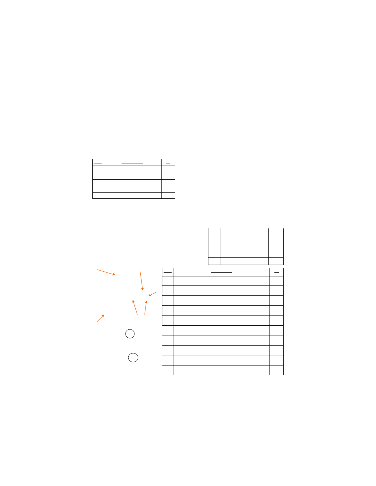
ITEM DESCRIPTION PN
1 6‟ (1829mm) Wash Down Hose w/Fittings 12541
2 Wash Down Hose & Nozzle Assembly 12675
3 Proximity Sensor Actuator 18A059
4 Cool II Handle 22734
5 1⁄2"(13mm) S/S Locking Seal Inline Plug 24A208
ITEM DESCRIPTION PN
1 Replacement Frame Set 21A284
2 Replacement “Upper” Screen 21A285
3 Replacement Baffle Assembly 21A286
4 Replacement “Lower” Screen 21A287
ITEM DESCRIPTION PN
5 1/2" (13mm) Black Iron Close Nipple 24003
6 3/8"(10mm) x 7" (177.8mm) Black Iron Nipple 24470
7 1/2" (13mm) S/S Locking Seal Inline Plug 24A208
8 1/2" (13mm) Handle Assy With 90˚ Black Iron Elbow 19A598
9 Top Compression Cap (Knurl Knob) 24A153
10 11" (279mm) Standpipe Clip 29A052
11 9 3/8" x 16 7/8" (238mm x 429mm) Baffle 29A060
12 11" x 18 1/4" (279mm x 464mm) Filter Pad 29A059
12 Case of (PN 29A059) Filter Pads 29A057
KIT 11" x 18 1/4" (279mm x 464mm) Baffle Kit consists of items 9,10&11 29A058
11
12
MAGEPAD MAGNESOL IMPREGNATED FILTER PAD
WITH STANDPIPE AND DOCKING ASSEMBLY
PN 12B178
MICRO-MESH S/S FILTER SCREEN
PN 21A278
Page 34
30A134
Page 42

30A134
PAR-3-H CE GAS FRYER W/ U23 COOKING COMPUTER
Page 35
WIRING DIAGRAM
Page 43

THIS PAGE INTENTIONALLY BLANK
Page 36
30A134
 Loading...