

Page 1

TIL NUMBER:
02-110
REVISED DATE:
January 2003
(added Part Number
to TIL btm of pg1)
SUBJECT
GAS ULTRAFRYER MODELS PAR-1 ANDPAR-2 FRYER KNOB OPERATOR
ON/OFF SWITCH RETROFIT
I. PURPOSE: New Ultrafryer Gas Fryers built AFTER March 1, 2000 will be equipped with a more
user friendly and readily available TOGGLE ON/OFF SWITCH and an AMBER POWER IN-
DICATOR LAMP in lieu of the illuminated KNOB OPERATOR ON/OFF SWITCH. A Toggle
ON/OFF Switch Assembly retrot kit is now available that can be used to replace any defective Knob
Operator ON/OFF switches in Model PAR-1 and PAR-2 gas fryers presently in use. This Technical Information Letter (TIL) will provide a description of a Toggle ON/OFF Switch Assembly and
step-by-step procedures to replace a defective knob operator ON/OFF switch with a toggle ON/OFF
switch assembly.
II. PRECAUTIONS:
A. This TIL is applicable to all Model PAR-1 and PAR-2 Ultrafryer gas fryers.
B. Defective Knob Operator ON/OFF Switches which fail in a fryer manufactured between
C. Fryers manufactured AFTER AUGUST 1998 which are equipped with a FIVE (5) WIRE
D. It is strongly recommended that defective knob operator ON/OFF switches be replaced
E. Illuminated push button ON/OFF switches installed in early model PAR-1 fryers can also
30A071
JANUARY 1, 1999 and FEBRUARY 1, 2000 will be replaced with a Toggle ON/OFF
Switch Assembly at the expense of Ultrafryer Systems. To determine the warranty status
of a fryer with a defective knob operator ON/OFF switch, contact the Customer Service
Department at 1-800-525-8130 or send an E-mail to Ultrafryer Service@afce.com
Knob Operator ON/OFF Switch can be retrotted according to procedures in paragraph
VC2 and fryers manufactured BEFORE AUGUST 1998 with a FOUR (4) WIRE switch
can be retrotted according to paragraph V C 1.
with a Toggle ON/OFF Switch Assembly and that ALL switches in a fryer bank be replaced with toggle ON/OFF switch assemblies upon failure of the rst switch.
be replaced with the Toggle ON/OFF Switch Assembly using this TIL as a guide.
1
Page 2

III. TOGGLE ON/OFF SWITCH ASSEMBLY DESCRIPTION – The Toggle ON/OFF Switch As-
sembly is housed in a stainless steel box 3” W x 3” H x 1” D containing; 1) a 125 volt 6 amp SPDT
toggle switch PN 18A287, 2) a 125 volt 3 watt snaplight with amber lens PN 23A056, 3) an ON/OFF
switch guard PN 18-129 and switch boot PN 23-402, 4) four (4) 16 gauge stranded wires 18 inches
long with BLACK, BLUE, RED and WHITE insulation and 5) ve (5) wire nuts for use in connecting the toggle ON/OFF switch assembly to the fryers electrical wiring.
TOGGLE ON/OFF SWITCH ASSEMBLY
PN 12A651
IV KNOB OPERATOR/PUSH BUTTON ON/OFF SWITCH REMOVAL –
A. CAREFULLY remove a defective knob operator ON/OFF switch as follows:
KNOB OPERATOR SWITCH
1. Turn electrical power to the fryer OFF; then lower/remove the Temperature Control Access Panel from the fryer.
2
Page 3
2. Separate the knob operator ON/OFF switch wiring connectors from the fryer wiring har-
ness as follows;
a. If applicable disconnect the two (2) pin white socket with a WHITE and YELLOW
wire from the two (2) pin white plug attached to gas burner indicator lamp with a
WHITE and YELLOW wire.
b. If applicable, disconnect the two (2) pin white socket with one (1) YELLOW wire
and a YELLOW jumper wire from the two (2) pin plug attached to the fryer wiring
harness.
c. Disconnect the FOUR (4) or FIVE (5) wire white socket from the mating plug con-
taining four (4) or ve (5) wires.
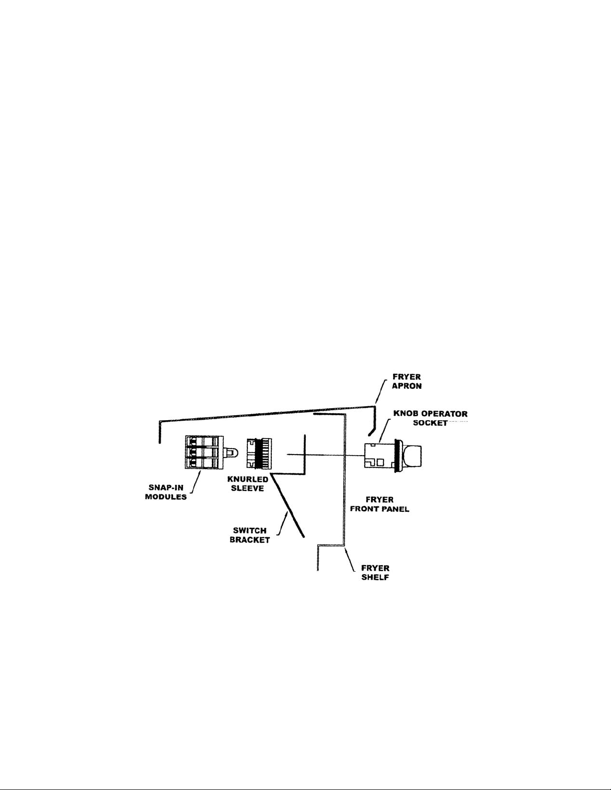
3. Separate the knob operator BASE with the three (3) snap-in modules and white sockets
from the KNOB OPERATOR by pushing the LOCKING LEVER, identied above,
UP while pulling the base towards the rear of the fryer.
4. Remove the knob operator BASE, and if applicable, the switch bracket, shown below,
from the front panel by removing the KNURLED SLEEVE. NOTE: Retain the BASE
with the white sockets for determining wire connections to the toggle ON/OFF switch
assembly.
5. THOROUGHLY clean the front and rear area around the d” switch mounting
hole to remove grease and any other debris.
3
Page 4
V. TOGGLE ON/OFF SWITCH ASSEMBLY INSTALLATION
A. Separate the toggle ON/OFF switch assembly from the retrot kit and place the ve (5) wire
nuts to one side for use later.
B. CAREFULLY mount the toggle ON/OFF switch assembly on the front panel of the fryer as
follows:
1. Remove the w” lock nut from the tting on the rear of the switch box.
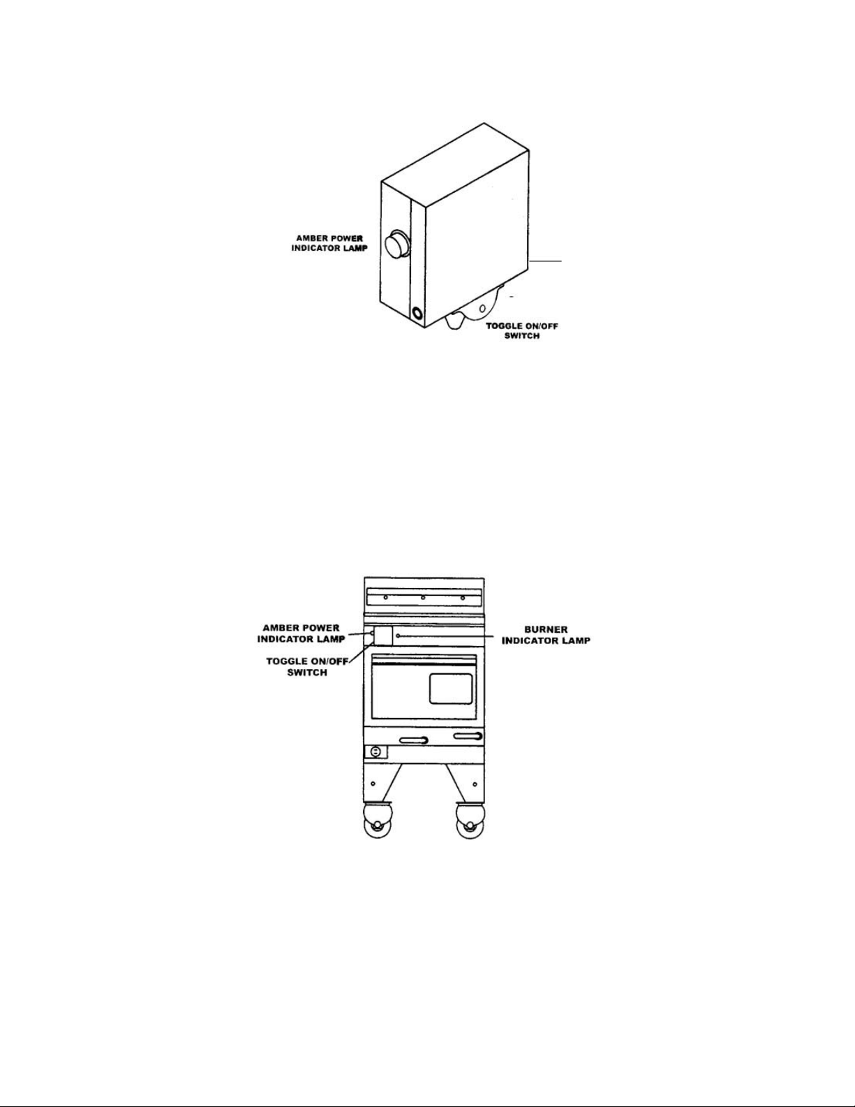
2. Place the assembly in front of the d” mounting hole in the front panel of the fryer
with the switch towards the FLOOR and the amber light towards the LEFT of the
fryer as shown below.
.
3. When the assembly is positioned as shown above, feed the BLACK, BLUE, RED
and WHITE wires through the d” hole; then insert the w” tting on the rear of the
assembly in the d” hole and SECURE the assembly to the front panel using the w”
lock nut removed above.
FRONT VIEW
C. Examine the knob operator BASE removed in step IVA4 to determine if it has a FOUR (4) or
FIVE (5) wire white socket attached; then connect the BLACK, BLUE, RED and WHITE
wires of the toggle ON/OFF switch assembly to the fryer wiring harness as follows:
4
Page 5

1. Fryer with FOUR (4) wire white socket:
a. CAREFULLY remove the TWO two (2) pin white plugs and four (4) pin
white plug, previously connected to the knob operator switch by cutting the
wires about 1” from the plug.
b. Remove c” of insulation from the end of each wire; then connect these seven
wires as follows:
1) Connect the two (2) YELLOW wires together and secure this connection using a wire nut provided.
2) Connect the WHITE wire attached to the RED burner indicator lamp, the WHITE wire cut from the 4 pin white plug and the
WHITE wire attached to the toggle ON/OFF switch assembly
together and SECURE this connection with a wire nut provided.
3) Connect the BLACK, BLUE and BLUE/WHITE wires cut from
the 4 pin white plug to the remaining three (3) wires attached to
the toggle ON/OFF switch assembly together, as shown below, and
secure these connections with wire nuts provided.
FRYER WIRE TOGGLE SWITCH WIRE
BLACK BLACK
BLUE/WHITE BLUE
BLUE RED
2. Fryer with FIVE (5) wire white socket:
a. CAREFULLY remove the ve (5) pin white plug, previously connected to
the knob operator switch by cutting the wires about 1” from the plug.
b. Remove c” of insulation from the end of each wire; then connect these
seven wires as follows:
1) Connect the YELLOW wire cut from the 5 pin white plug to one
(1) BLACK wire attached to the red indicator lamp with a wire nut
provided
2) Connect the remaining BLACK wire attached to the RED burner
indicator lamp, the WHITE wire cut from the 5 pin white plug and
the WHITE wire attached to the toggle ON/OFF switch assembly
together and SECURE these connections with a wire nut provided.
3) Connect the BLACK, BLUE and RED wires cut from the 5 pin
white plug to the remaining 3 wires attached to the toggle ON/OFF
switch assembly together, as shown below, and secure these connections with wire nuts provided.
5
Page 6

FRYER WIRE TOGGLE SWITCH WIRE
BLACK BLACK
BLUE BLUE
RED RED
C. Neatly secure all loose wires with plastic cable tyes, and seal the perimeter of the toggle ON/
OFF switchbox with silicone.
VI TOGGLE ON/OFF SWITCH ASSEMBLY TEST - Raise/replace the Temperature Control Ac-
cess Panel on the fryer, turn electrical power to the fryer ON; then test operate the fryer and ltration
system as follows:
A. Turn the toggle ON/OFF switch to the ON position. The AMBER power indicator lamp
should LIGHT.
B. Turn the FILTER PUMP LEVER to the open DOWN position. The pump motor SHOULD
NOT come on. Return the lter pump lever to the closed UP position.
C. Activate the applicable control [Default-to-Manual Restart (DTMR) Control, Ultrastat 21
Cooking Computer, Adjustable Digital Temperature Control (ADTC), etc.]. The following
should occur:
1. The RED burner indicator lamp will LIGHT.
2. Blower motor will come ON activating the centrifugal switch.
3. The centrifugal switch will CLOSE completing the electrical circuit to the transformer.
4. The transformer will supply 24 volts to the IGNITER MODULE and GAS CON-
TROL VALVE and the igniter will SPARK lighting the gas in the burner.
D. Turn the toggle ON/OFF switch to the OFF position. The AMBER power indicator lamp
should turn OFF.
E. Turn the FILTER PUMP LEVER to the open DOWN position. The pump motor should
come ON. Return the lter pump lever to the closed UP position.
NOTE: QUESTIONS TO THE CONTENTS OF THIS PUBLICATION SHOULD BE RE-
FERRED TO THE CUSTOMER SERVICE DEPARTMENT AT 1-800-525-8130.
6
 Loading...