

Page 1
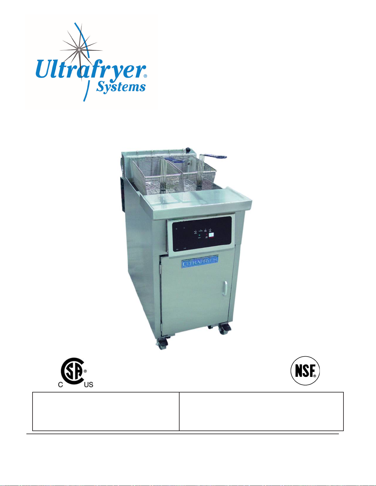
ULTRAFRYER GAS FRYER
MODEL F-P25-14 / 18 / 20 / 24
OPERATION INSTRUCTIONS
FOR YOUR SAFETY
Do not store or use gasoline or other ammable vapors or
liquids in the vicinity of this or other appliance.
302 Spencer Lane • P.O. Box 5369
WARNING
Improper Installation, adjustment, alteration, service, or maintenance can cause property damage, injury, or death. Read the
installation, operating, and maintenance instructions thoroughly
before installing or servicing this equipment.
San Antonio, Texas 78201
(800) 525-8130 • (210) 731-5000 • Fax: (210) 731-5099
www.ultrafryer.com
PN 30A169 rev Jan2008 1
PDF compression, OCR, web optimization using a watermarked evaluation copy of CVISION PDFCompressor
Page 2

PREFACE
This Manual was written and published by the Engineering Department, Ultrafryer Systems for use by personnel
who will operate a Model P25 Gas Fryer in a commercial cooking environment.
This appliance is intended for professional use and is to be operated by qualied personnel.
Throughout this manual, NOTES, CAUTIONS, and WARNINGS are used to alert the operator to items of spe-
cial circumstances. These items are identied as follows:
NOTE: Pull on the lter tub to ASSURE the male docking plug is SEATED in the female bulkhead
socket.
CAUTION: To assure producing a quality product while prolonging the life expectancy of the fryer,
ensure that the ltering, boil-out, and cleaning instructions are strictly followed.
WARNING: Do not allow any cleaning solution or water to splash into a vessel of hot cooking
oil, as it will contaminate the oil and may cause the oil to splatter, causing severe burns.
This manual is intended as a guide for all model PNP fryers, regardless of conguration, ltration options and
controllers. It is to be used in conjunction with the applicable controller manual that is included with the fryer.
Retain this manual for future reference.
PN 30A169 rev Jan2008 2
PDF compression, OCR, web optimization using a watermarked evaluation copy of CVISION PDFCompressor
Page 3

TABLE OF CONTENTS
GENERAL INFORMATION
Warranty. . . . . . . . . . . . . . . . . . . . . . . . . . . . . . . . . . . . . . . . . . . . . . . . . . . . . . . . . . . . . . . . . . 6
Safety . . . . . . . . . . . . . . . . . . . . . . . . . . . . . . . . . . . . . . . . . . . . . . . . . . . . . . . . . . . . . . . . . . . . . 7
Description / Specications . . . . . . . . . . . . . . . . . . . . . . . . . . . . . . . . . . . . . . . . . . . . . . . . . . 7
Dimensions & Operational Requirements . . . . . . . . . . . . . . . . . . . . . . . . . . . . . . . . . . . . . . 7
Operating Controls Location . . . . . . . . . . . . . . . . . . . . . . . . . . . . . . . . . . . . . . . . . . . . . . . . . 8
Operating Controls . . . . . . . . . . . . . . . . . . . . . . . . . . . . . . . . . . . . . . . . . . . . . . . . . . . . . . . . . 9
Automatic Safety Features . . . . . . . . . . . . . . . . . . . . . . . . . . . . . . . . . . . . . . . . . . . . . . . . . . . 9
Rating Plate. . . . . . . . . . . . . . . . . . . . . . . . . . . . . . . . . . . . . . . . . . . . . . . . . . . . . . . . . . . . . . . . 9
Inlet Gas Line Sizing . . . . . . . . . . . . . . . . . . . . . . . . . . . . . . . . . . . . . . . . . . . . . . . . . . . . . . . 10
Inlet Gas Requirements. . . . . . . . . . . . . . . . . . . . . . . . . . . . . . . . . . . . . . . . . . . . . . . . . . . . . 10
PRE-INSTALLATION
General . . . . . . . . . . . . . . . . . . . . . . . . . . . . . . . . . . . . . . . . . . . . . . . . . . . . . . . . . . . . . . . . . . 12
Standards . . . . . . . . . . . . . . . . . . . . . . . . . . . . . . . . . . . . . . . . . . . . . . . . . . . . . . . . . . . . . . . . 12
Air Supply & Ventilation . . . . . . . . . . . . . . . . . . . . . . . . . . . . . . . . . . . . . . . . . . . . . . . . . . . . 12
RECEIVING & INSTALLING
Unpacking. . . . . . . . . . . . . . . . . . . . . . . . . . . . . . . . . . . . . . . . . . . . . . . . . . . . . . . . . . . . . . . . 14
Installing. . . . . . . . . . . . . . . . . . . . . . . . . . . . . . . . . . . . . . . . . . . . . . . . . . . . . . . . . . . . . . . . . 14
Leveling. . . . . . . . . . . . . . . . . . . . . . . . . . . . . . . . . . . . . . . . . . . . . . . . . . . . . . . . . . . . . . . . . . 14
Gas Connection . . . . . . . . . . . . . . . . . . . . . . . . . . . . . . . . . . . . . . . . . . . . . . . . . . . . . . . . . . . 15
Electrical Connection . . . . . . . . . . . . . . . . . . . . . . . . . . . . . . . . . . . . . . . . . . . . . . . . . . . . . . 15
Cooking Computers . . . . . . . . . . . . . . . . . . . . . . . . . . . . . . . . . . . . . . . . . . . . . . . . . . . . . . . 16
INITIAL START-UP
Cleaning . . . . . . . . . . . . . . . . . . . . . . . . . . . . . . . . . . . . . . . . . . . . . . . . . . . . . . . . . . . . . . . . . 19
Start-Up . . . . . . . . . . . . . . . . . . . . . . . . . . . . . . . . . . . . . . . . . . . . . . . . . . . . . . . . . . . . . . . . . 19
Lighting Instructions. . . . . . . . . . . . . . . . . . . . . . . . . . . . . . . . . . . . . . . . . . . . . . . . . . . . . . . 19
Sequence Of Ignition . . . . . . . . . . . . . . . . . . . . . . . . . . . . . . . . . . . . . . . . . . . . . . . . . . . . . . . 19
Burner Operation Test. . . . . . . . . . . . . . . . . . . . . . . . . . . . . . . . . . . . . . . . . . . . . . . . . . . . . . 19
Test Start-Up . . . . . . . . . . . . . . . . . . . . . . . . . . . . . . . . . . . . . . . . . . . . . . . . . . . . . . . . . . . . . 19
ABBREVIATED OPERATING INSTRUCTIONS
General . . . . . . . . . . . . . . . . . . . . . . . . . . . . . . . . . . . . . . . . . . . . . . . . . . . . . . . . . . . . . . . . . . 21
Cooking. . . . . . . . . . . . . . . . . . . . . . . . . . . . . . . . . . . . . . . . . . . . . . . . . . . . . . . . . . . . . . . . . . 21
Filtering Shortening. . . . . . . . . . . . . . . . . . . . . . . . . . . . . . . . . . . . . . . . . . . . . . . . . . . . . . . . 21
Leveling Shortening. . . . . . . . . . . . . . . . . . . . . . . . . . . . . . . . . . . . . . . . . . . . . . . . . . . . . . . . 21
Boiling Out Fryer . . . . . . . . . . . . . . . . . . . . . . . . . . . . . . . . . . . . . . . . . . . . . . . . . . . . . . . . . . 22
Closing / Shutdown Instructions . . . . . . . . . . . . . . . . . . . . . . . . . . . . . . . . . . . . . . . . . . . . . 22
PN 30A169 rev Jan2008 3
PDF compression, OCR, web optimization using a watermarked evaluation copy of CVISION PDFCompressor
Page 4

TABLE OF CONTENTS.....Continued
PREVENTIVE MAINTENANCE & TROUBLESHOOTING
Preventive Maintenance . . . . . . . . . . . . . . . . . . . . . . . . . . . . . . . . . . . . . . . . . . . . . . . . . . . . 24
Troubleshooting . . . . . . . . . . . . . . . . . . . . . . . . . . . . . . . . . . . . . . . . . . . . . . . . . . . . . . . . . . 24
Troubleshooting Chart . . . . . . . . . . . . . . . . . . . . . . . . . . . . . . . . . . . . . . . . . . . . . . . . . . . . . 24
CLEANING . . . . . . . . . . . . . . . . . . . . . . . . . . . . . . . . . . . . . . . . . . . . . . . . . . . . . . . . . . . . . . . . 27
FILTER TUB ASSEMBLY & INSTALLATION
Filter Tub Assembly . . . . . . . . . . . . . . . . . . . . . . . . . . . . . . . . . . . . . . . . . . . . . . . . . . . . . . . . 29
Filter Tub Installation . . . . . . . . . . . . . . . . . . . . . . . . . . . . . . . . . . . . . . . . . . . . . . . . . . . . . . 29
TECHNICAL ASSISTANCE & ORDERING INFORMATION
Technical Assistance . . . . . . . . . . . . . . . . . . . . . . . . . . . . . . . . . . . . . . . . . . . . . . . . . . . . . . . 31
Ordering Information . . . . . . . . . . . . . . . . . . . . . . . . . . . . . . . . . . . . . . . . . . . . . . . . . . . . . . 31
RECOMMENDED SPARE PARTS . . . . . . . . . . . . . . . . . . . . . . . . . . . . . . . . . . . . . . . . . . . . 33
PARTS IDENTIFICATION
Parts Identication . . . . . . . . . . . . . . . . . . . . . . . . . . . . . . . . . . . . . . . . . . . . . . . . . . . . . . . . 35
WIRING DIAGRAMS . . . . . . . . . . . . . . . . . . . . . . . . . . . . . . . . . . . . . . . . . . . . . . . . . . . . . . . 42
PN 30A169 rev Jan2008 4
PDF compression, OCR, web optimization using a watermarked evaluation copy of CVISION PDFCompressor
Page 5

GENERAL INFORMATION
PN 30A169 rev Jan2008 5
PDF compression, OCR, web optimization using a watermarked evaluation copy of CVISION PDFCompressor
Page 6

A. Warranty
ULTRAFRYER® LIMITED WARRANTY: PAR-2
Ultrafryer Systems warrants to the original purchaser of a gas Ultrafryer® sold within the United States that it will be
free of defects in material and workmanship for the periods listed below:
STAINLESS STEEL FRYER VAT – Stainless Steel fryer vats are warranted for (10) ten years upon the terms hereinafter
described. The (10) ten year warranty coverage applies ONLY to the Stainless Steel fryer vat and does not apply to the other
components such as controls, re boxes, gaskets, mounting hardware, or the heat shield weldment. The (10) ten year limited
warranty coverage for the Stainless Steel fryer vats are as follows: (1) Vats that fail due to faulty workmanship or materials
within the rst twelve (12) months from the date of initial start up will be exchanged at no cost. Standard delivery ground
freight will be prepaid by Ultrafryer Systems for rst year failures only. The cost of labor to install the replacement vat will
be covered by Ultrafryer Systems for vats, which fail within twelve (12) months from the date of initial start up. Labor for vat
replacements after the rst year is the responsibility of the owner.(2) Vats that fail within the second through fth year will be
exchanged at $250.00 FOB San Antonio. (3) Vats that fail within the sixth through eight year will be exchanged at 50% of current selling price of said vat FOB San Antonio. (4) Vats that fail within the ninth through tenth year will be exchanged at 70%
of the current selling price of said vat FOB San Antonio. (Example: If the current selling price for a particular vat is $2,000.00,
then a failure during the sixth through eighth year would be exchanged for $1,000.00; if the failure occurred in the ninth or tenth
year it would be exchanged for $1,400.00.) Proper credit issue for vat failures is contingent upon receipt, by Ultrafryer Systems,
of the serial number identication tag for any failed vat.
ULTRAFRYER PARTS – All parts on the Ultrafryer® are covered for a period of one (1) year from the initial date of start up.
This is to include gas valves, switches, thermostats, etc. Ultrafryer Systems reserves the right to charge for certain parts such as
computers, lter pumps and motors or any item over the amount of $100.00 until Ultrafryer Systems receives the defective part
back. After inspection, credit for the part will be issued to the purchaser provided the part is deemed defective and that
defect is not the result of neglect or abuse by the user. The shortening ltration system, (hoses) are warranted for ninety (90)
days from the initial date of start up.
PROCESSING WARRANTY CLAIMS – The equipment owner must promptly notify Ultrafryer Systems Warranty Department of any alleged defects as soon as they are discovered by calling 1-800-525-8130. After such notice, the Warranty Department will perform its obligation under this warranty within a commercially reasonable period of time. If alleged defects develop
after normal business hours, on weekends or on holidays the owner must call Ultrafryer Systems rst at the above number. This
number is monitored 24 hours a day, 7 days a week. Ultrafryer Systems will notify an authorized service agent to make repairs
during normal hours or after hours. Any parts that need to be shipped back to Ultrafryer Systems will be shipped back prepaid
by the customer marked with the processing number and to the attention of the WARRANTY DEPARTMENT.
NON WARRANTY COVERAGE – This warranty does not include coverage for any consequential cost of damages including,
but not limited to, any loss in store sales, spoiled food products, transportation, duty or custom cost. This warranty does not
cover the Ultrafryer® exported to countries outside the United States and its territories. This warranty does not cover original
installation and adjustments such as leveling, calibrations and electrical and gas connections. This warranty does not cover travel
over 100 miles or 2 hours driving time from the location of the Ultrafryer® or overtime or holiday charges unless the Warranty
Department granted prior approval. This warranty does not cover damage due to misuse, abuse, alteration or accident. This
Warranty does not cover improper or unauthorized repair or installation, damage in shipment, normal maintenance items such as
gaskets, hoses, and exterior nishes. Ultrafryer Systems will begin the fryer warranty one week after shipment but will adjust the
warranty upon receiving approved documentation. We reserve the right to void component part warranty on any Ultrafryer that
is stored more than six (6) months after shipment from Ultrafryer Systems and not put into service.
LABOR COVERAGE – The cost for labor to replace parts are covered for one (1) year after the initial start up. The Warranty
Department must be promptly notied of any defects within the rst year of operation. The labor warranty does not include
the cost to repair or clear dirty lter systems or perform any adjustments that would normally fall under the tasks associated with
a proper start up and/or demonstration. Labor is covered by Ultrafryer Systems for repairs by an AUTHORIZED service
agent. Owner is responsible for all costs associated with fryer installation and start up unless prior arrangements have been
made with Ultrafryer Systems.
DISCLAMIER OF WARRANTIES
Other than as stated herein, ULTRAFRYER SYSTEMS makes no warranty of any kind, express or implied, including
but not limited to any warranty of merchantability of tness for a particular purpose, including trade usage. Ultrafryer
Systems’ sole obligation, and purchaser’s sole remedy, under this warranty is repair or replacement, at the discretion of
Ultrafryer Systems, of any part or component that proves to be defective in materials or workmanship. In no event shall
Ultrafryer Systems be liable for consequential, incidental, or special loss or damages arising from the use of, or inability
to use, the ULTRAFRYER®. This limited warranty is the only and complete statement with respect to warranties of
NEW Ultrafryer® PAR-2,Gas ULTRAFRYERS® sold after June 1st, 2000. There are no other documents or oral statements for which Ultrafryer Systems will be responsible. Effective 2-1-2008.
PN 30A169 rev Jan2008 6
PDF compression, OCR, web optimization using a watermarked evaluation copy of CVISION PDFCompressor
Page 7
B. SAFETY
The major safety concern associated with the Ultrafryer Gas Fryer is burns from hot shortening. In order to prevent
serious burns, good housekeeping habits are required. The oor in front of and the area around the fryer should be kept
clean and dry. Whenever anything is placed in to a fryer vat, care should be used not to splash the hot shortening.
Product
an apron
120 volts single
without rst disconnect
water. To do so can result in serious
should always be “PLACED” into the shortening, NOT THROWN. Safety goggles, neoprene insulated gloves and
must be worn while ltering or boiling-out a fryer vat. Electrical controls on all Ultrafryer Fryers operate on
phase electrical power. No adjustments or replacement of electrical controls should ever be attempted
ing
electrical power. The fryer should never be operated with wet hands or while standing in
electrical shock or death.
C. DESCRIPTION / SPECIFICATIONS
The Ultrafryer Gas Fryer is constructed from 16 & 18 gauge, “300” series, polished, satin nish stainless steel. Most Models
are equipped with a Default-To-Manual-Restart (DTMR) Control or an Ultrastat 11 Cooking Computer; however ,
customers may request the fryer be equipped with an Ultrastat 21 or Ultrastat 25 Cooking Computer. In addition, the
Model PAR25 can be equipped with the EZ Dock Filtration System, which uses a stainless steel Filter Screen. The
Customer has the option of ordering a Filter Pad Assembly that uses an impregnated Filter Pad in lieu
of the
S/S lter screen. The dimensions and gas rating of the Model PAR25 Gas Fryer are as follows:
D.
ULTRAFRYER MODEL PAR3/PAR25 GAS FRYER DIMENSIONS & OPERATIONAL REQUIREMENTS
14” VAT
18” VAT
20” VAT
24” VAT
Overall Width 15.625 in 397 mm 19.625 in 498 mm 21.625 in 549 mm 25.625 in 651 mm
Overall Depth 30.75 in 781 mm 30.75 in 781 mm 30.75 in 781 mm 30.75 in 781 mm
Work Height 35.75 in 908 mm 35.75 in 908 mm 35.75 in 908 mm 35.75 in 908 mm
Oil Capacity - High Level 45 Lb 20.4 kg 75 Lb 34 kg 98 Lb 44.4 kg 120 Lb 54.4 kg
Oil Capacity - Low Level 35 Lb 15.9 kg 75 Lb 34 kg 98 Lb 44.4 kg 120 Lb 54.4 kg
Gas Rating
Butane
Natural
Propane
70,000
BTU/hr
80,000
BTU/hr
80,000
BTU/hr
73.9 MJ/hr
84.4 MJ/hr
84.4 MJ/hr
80,000
BTU/hr
85,000
BTU/hr
85,000
BTU/hr
84.4 MJ/hr
89.7 MJ/hr
89.7 MJ/hr
70,000
BTU/hr
80,000
BTU/hr
80,000
BTU/hr
73.9 MJ/hr
84.4 MJ/hr
84.4 MJ/hr
80,000
BTU/hr
85,000
BTU/hr
85,000
BTU/hr
84.4 MJ/hr
89.7 MJ/hr
89.7 MJ/hr
Orice Drill Size
Butane #42 2.7 mm #42 2.7 mm
Natural #20 #18 #20 #18
Propane #38 #33 #38 #33
Gas Valve Pressure
Butane (W.C.) 10”w.c. 254 mm 10”w.c. 254 mm 10”w.c. 254mm 10”w.c. 254mm
Natural (W.C.) 4”w.c. 102 mm 4”w.c. 102 mm 4”w.c. 102mm 4”w.c. 102mm
Propane (W.C.) 10”w.c. 254 mm 10”w.c. 254 mm 10”w.c. 254mm 10”w.c. 254mm
Inlet ow Required at
STP
Butane 22 ft3/hr 0.62 m3/hr 25 ft3/hr 0.71 m3/hr 22 ft3/hr 0.62 m3/hr 25 ft3/hr 0.71 m3/hr
Natural 80 ft3/hr 2.27 m3/hr 85 ft3/hr 2.40 m3/hr 80 ft3/hr 2.27 m3/hr 85 ft3/hr 2.40 m3/hr
Propane 32 ft3/hr 0.91 m3/hr 34 ft3/hr 0.96 m3/hr 32 ft3/hr 0.91 m3/hr 34 ft3/hr 0.96 m3/hr
Shipping Cube 10 ft
3
3.05 m
3
12 ft
3
3.66 m
3
14 ft
3
4.27 m
3
16 ft
3
4.88 m
3
Shipping Weight 165 Lb 74 kg 170 Lb 77 kg 177 Lb 80 kg 250 Lb 113 kg
Power Input All units use 120Volt 6 amp 60 Hz 1 O
NOTE:
CONSULT THE INCLUDED COMPUTER CONTROLLER MANUAL AND FILTRATION MANUAL FOR TEST START-UP,
OPERATIONS, COOKING, FILTERING, AND BOIL OUT PROCEDURES.
PN 30A169 rev Jan2008 7
PDF compression, OCR, web optimization using a watermarked evaluation copy of CVISION PDFCompressor
Page 8
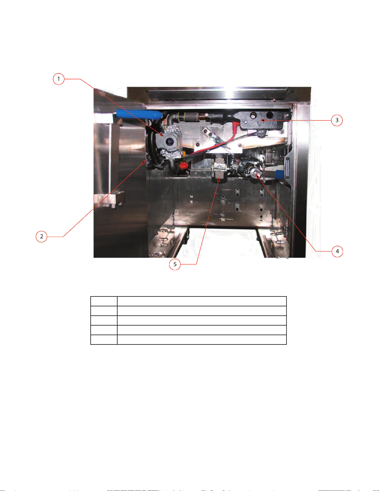
E. OPERATING CONTROLS LOCATION
MODEL PAR25
GAS FRYER
1 Gas Regulator and Shutoff Valve
2 High Limit
3 Burner
4 Docking Connection
5 Main Drain Valve
PN 30A169 rev Jan2008 8
PDF compression, OCR, web optimization using a watermarked evaluation copy of CVISION PDFCompressor
Page 9
MODEL PAR25 GAS FRYER
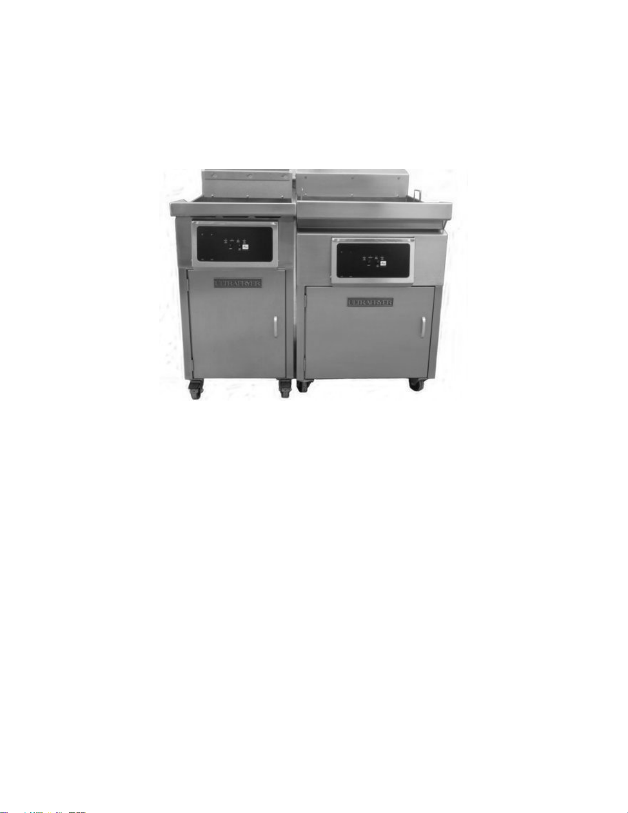
F. OPERATING CONTROLS:
The “basic” PAR25 gas fryer is equipped with an Electronic Thermostat and
however, customers may request the fryer be equipped with an “optional” Ultrastat Cooking Computer, such as an Ultrastat 11,21
or 25 Cooking Computer. When applicable, operating instructions for the Ultrastat Cooking Computer will be provided with the
fryer. Operating controls on the Model PAR25 gas fryer include the Toggle HEAT/OFF Switch, AMBER
RED Burner Indicator Lamp, and the applicable Temperature Controller. These controls are mounted on the Temperature
Access Panel; and the Electronic Thermostat and other fryer controls are located behind the access door. The main drain valve and
(if applicable) shortening return levers are located behind the Service Access Panel.
Default-to-Manual-Restart (DTMR) control;
Power Indicator Lamp,
Control
Figure (from left to right): 18” Model Par25 and 24” Model Par25
G. AUTOMATIC SAFETY FEATURES:
1. High limit thermostat to shut off gas to the main burners by opening a solenoid-actuated safety valve in the combination gas
control valve.
2. Combination gas control valve which includes a built-in pressure regulator and manual valve.
3. Sensing circuit within the spark ignitor module to turn gas to the fryer OFF if a burner FLAME OUT occurs.
4. A Drain Valve Safety Switch and a Default-to-Off circuit in the Default-to-Manual-Restart (DTMR) Control that will DIS-
ABLE the fryer each time the drain valve is OPENED.
5. An AIR PRESSURE switch to open the electrical circuit to the spark ignitor and gas valve which will turn the gas to the fryer
OFF in the event the blower motor fails.
H. RATING PLATE:
Information on this plate includes the model and serial number; BTU/HR input rating of the burners; gas manifold pressure in
inches W.C. ; minimum inlet gas
communicating
of the Service Access door.
with ULTRAFRYER SYSTEMS or requesting special parts or information. The rating plate is located on the inside
required, orice size; and type of gas. This data is essential for proper identication when
THE FRYER MUST BE CONNECTED ONLY TO THE TYPE OF GAS IDENTIFIED ON THIS RATING PLATE!
PN 30A169 rev Jan2008 9
PDF compression, OCR, web optimization using a watermarked evaluation copy of CVISION PDFCompressor
Page 10
I. INLET GAS LINE SIZING:
The Table below is used to calculate the size (diameter) of the inlet gas line from the building regulator to the fryer manifold.
INLET GAS LINE REQUIREMENTS
PIPE
LENGTH
Feet
(Meters)
15
(4.6)
30
(9.1)
45
(13.7)
60
(18.3)
75
(22.9)
90
(27.4)
105
(32.0)
120
(36.6)
150
(45.7)
180
(54.9)
210
(64.0)
240
(73.2)
270
(82.3)
300
(91.4)
450
(137.2)
600
(182.9)
NOTE: 1) FT3/HR (M3/HR) values may vary due to heating value and specic gravity of gas supplied by local companies.
2) To determine the inlet gas line diameter for the distance between the fryer and main gas regulator, locate the FT3/HR (M3/HR) of gas required for the fryer and
pipe length and read the pipe diameter on the top row. For example: a PAR25 fryer operating on NATURAL GAS requires 90 FT3/HR (2.5 M3/HR)
of gas at the fryer’s inlet gas manifold. If the fryer bank is located 60 feet from the building gas regulator, a 1” (25mm) diameter gas line MUST be installed
between the manifold and regulator.
"
(13 mm)
62
(1.7)
43
(1.2)
35
(1.0)
30
(0.8)
27
(0.8)
25
(0.7)
23
(0.6)
21
(0.6)
19
(0.5)
17
(0.5)
16
(0.4)
15
(0.4)
14
(0.4)
14
(0.4)
11
(0.3)
10
(0.3)
"
(19mm)
170
(4.7)
120
(3.4)
98
(2.7)
84
(2.4)
76
(2.1)
70
(2.0)
64
(1.8)
60
(1.7)
54
(1.5)
49
(1.4)
44
(1.2)
43
(1.2)
40
(1.1)
38
(1.1)
31
(0.9)
27
(0.8)
(25mm)
PIPE DIAMETERS (inches & (mm equivalents))
Maximum Allowable Flow (Shown in ft3/hr (M3/hr))
1
350
(9.8)
245
(6.9)
200
(5.6)
175
(4.9)
155
(4.3)
145
(4.1)
132
(3.7)
125
(3.5)
110
(3.1)
100
(2.8)
94
(2.6)
88
(2.5)
83
(2.3)
79
(2.2)
64
(1.8)
56
(1.6)
"
1
(32mm)
620
(17.4)
430
(12.0)
355
(9.9)
310
(8.7)
275
(7.7)
250
(7.0)
232
(6.5)
215
(6.0)
195
(5.5)
175
(4.9)
165
(4.6)
155
(4.3)
145
(4.1)
138
(3.9)
112
(3.1)
97
(2.7)
"
1
(38mm)
960
(26.9)
680
(19.0)
530
(14.8)
480
(13.4)
430
(12.0)
395
(11.1)
370
(10.4)
340
(9.5)
310
(8.7)
280
(7.8)
260
(7.3)
240
(6.7)
230
(6.4)
215
(6.0)
176
(4.9)
152
(4.3)
"
2
"
(51mm)
2,000
(56.0)
1,400
(39.2)
1,150
(32.2)
1,000
(28.0)
890
(24.9)
810
(22.7)
(750
(21.0)
700
(19.6)
630
(17.6)
570
(16.0)
530
(14.8)
500
(14.0)
470
(13.2)
440
(12.3)
360
(10.1)
315
(8.8)
2
(64mm)
3,500
(98.0)
2,450
(68.6)
2,000
(56.0)
1,760
(49.3)
1,560
(43.7)
1,430
(40.0)
1,300
(36.4)
1,200
(33.6)
1,080
(30.2)
960
(26.9)
890
(24.9)
840
(23.5)
780
(21.8)
750
(21.0)
630
(17.6)
530
(14.8)
"
3
"
(76mm)
5,400
(151.2)
3,800
(106.4)
3,200
(89.6)
2,700
(75.6)
2,450
(68.6)
2,260
(63.3)
2,100
(58.8)
1,950
(54.6)
1,750
(49.0)
1,600
(44.8)
1,450
(40.6)
1,350
(37.8)
1,300
(36.4)
1,250
(35.0)
1,000
(28.0)
860
(24.1)
4
"
(102mm)
11,200
(313.6)
7,900
(221.2)
7,900
(182.0)
5,600
(156.8)
5,000
(140.0)
4,550
(127.4)
4,200
(117.6)
4,000
(112.0)
3,550
(99.4)
3,200
(89.6)
3,000
(84.0)
2,800
(78.4)
2,650
(74.2)
2,500
(70.0)
2,050
(57.4)
1,750
(49.0)
J. GAS LINES
The Flexible Gas Line used to connect the gas manifold to the building gas supply line must be rated for the BTU/Hr (MJ/Hr)
designated for the Fryer. Flexible gas lines and their ratings stocked by Ultrafryer Systems are listed below:
FLEXIBLE GAS LINES STOCKED BY ULTRAFRYER SYSTEMS
NUMBER DESCRIPTION
24322
24323
24456
3/4" (19mm) Diameter Flexible Gas Line (w/quick connect
couplings) 48" (1219mm) long. Connect-It SSGC75-48-UCQ
1” (25mm) Diameter Flexible Gas Line (w/quick connect
couplings) 48" (1219mm) long. Connect-It SSGC100-48-UCQ
1 1/4" (32mm) Diameter Flexible Gas Line (w/quick connect
couplings) 48” (1219mm) long. Connect-It SSGC125-48-UCQ
225,000 (238)
435,000 (459)
875,000 (924)
RATING
BTU/HR (MJ/HR)
PN 30A169 rev Jan2008 10
PDF compression, OCR, web optimization using a watermarked evaluation copy of CVISION PDFCompressor
Page 11

PRE-INSTALLATION
PN 30A169 rev Jan2008 11
PDF compression, OCR, web optimization using a watermarked evaluation copy of CVISION PDFCompressor
Page 12

A. GENERAL: Safe and satisfactory operation of a Model PAR25 gas fryer depends on its proper installation. Installation
must conform to local codes or, in the absence of local codes, with the current National Fuel Gas Code ANSI Z223.1 (latest edi tion). In Canada, gas installation shall be in accordance with the current CAN/CGA B 149.1 and .2 installation codes and/or local
codes. Each Model PAR25 fryer should be installed as follows:
1. Placed beneath a properly designed exhaust hood
2. Installed by a licensed plumber.
3. Connected to the type gas for which the unit was fabricated as shown on the rating plate.
4. Connected to the proper size pressure regulator installed in the gas supply line and adjusted to the proper manifold pressure.
5. Connected to the main gas supply line with the proper size supply line.
6. Restrained by use of a restraining device to avoid splashing of hot liquid and to assure tension cannot be placed on the exible
gas line or ttings.
CLEARANCES: The appliance must be kept free and clear of all combustibles. The minimum clearance from combustible and
non-combustible construction is 6" (152 mm) from the sides, and 6" (152 mm) from rear. The fryer may be installed on combustible oors.
NOTE: Adequate clearances must be provided for servicing and proper operation.
B. STANDARDS: Installation must be planned in accordance with all applicable state and local codes, taking into account the following
standards
1. The fryer and its individual shut-off valve must be disconnected from the gas supply piping system during any pressure testing
2. The fryer must be isolated from the gas supply piping system by closing its individual manual shut-off valve during any pres-
3. When installed the fryer must be electrically grounded in accordance with local codes, or in the absence of local codes, in
4. Other applicable nationally recognized installation standards such as:
a. National Fuel Gas Code ANSI Z223.1 (latest edition)
American Gas Association
1515 Wilson Blvd.
Arlington, VA22209
b. NFPA Standards #54, #94 and #221 (latest edition)
National Fire Protection Association
470 Atlantic Avenue
Boston, MA 02110
c. ANSI Z21.69/CAN/CGA-6.16 AND Z21.41/CAN1 6.9
5. Exhaust vent hood, when installed must conform to the current NFPA 54-1 and Canadian CAN/CGA-1.11 (latest edition)
:
of that system at pressures in excess of psig (3.45kPa). In Canada, gas installation shall be in accordance with the current
CAN/CGA B 149.1 and .2 installation codes and/or local codes.
sure testing of the gas supply piping system at pressures equal to or less than psig (3.45kPA).
accordance with the current National Electrical code ANSI/NFPA 70 (latest edition). In Canada electrical installation must be
in accordance with the current CSA C22.1 Canadian Electrical Code and/or local codes.
NOTE: Local building codes will usually not permit a fryer with its open tank of hot oil to be installed immediately next to an
open ame of any type, whether a broiler or an open burner or range. Check local codes before beginning installation.
C. AIR SUPPLY AND VENTILATION: The area around the appliance must be kept clear of any combustible or ammable products
and avoid any obstruction to the ow of ventilation air as well as for ease of maintenance and service. NOTHING is to be stored
in the interior of the fryer’s cabinet except the lter tub assembly.
1. A means must be provided for any commercial, heavy duty-cooking appliance to exhaust combustion wastes outside of the
building. It is essential that a fryer be set under a powered exhaust vent hood or that an exhaust fan be provided in the wall
above the unit, as exhaust temperatures are in the vicinity of 400˚F (204˚C).
NOTE: Strong exhaust fans in a hood or in the overall air conditioning system can produce slight air drafts in the room, which
can interfere with burner performance and be hard to diagnose. Air movement should be checked during installation and
if burner problems persist, make-up air openings or bafes may have to be provided in the room.
2. Exhaust temperature, in addition to the open tank of hot oil, make the storage of anything on shelving over or behind the
fryer unsafe.
3. Filters and drip troughs should be part of any industrial hood, but consult local codes before constructing and installing any
hood.
4. Provisions must be made for an adequate supply of fresh air and adequate clearance must be maintained for air openings into
the combustion chamber.
PN 30A169 rev Jan2008 12
PDF compression, OCR, web optimization using a watermarked evaluation copy of CVISION PDFCompressor
Page 13

RECEIVING & INSTALLING
PN 30A169 rev Jan2008 13
PDF compression, OCR, web optimization using a watermarked evaluation copy of CVISION PDFCompressor
Page 14

A. UNPACKING: Check that the container is upright. Use an outward prying motion – DO NOT USE A HAMMER - to remove the
carton. Check the fryer for visible damage; if such damage has occurred do not refuse shipment, but contact the carrier and le
the appropriate freight claims.
B. INSTALLING: Roll the assembled fryer into the building, to its operating location.
WARNING: IMPROPER INSTALLATION, ADJUSTMENT, ALTERATION, SERVICE OR MAINTENANCE CAN CAUSE
PROPERTY DAMAGE, INJURY OR DEATH. READ THE INSTALLATION, OPERATING AND MAINTENANCE
INSTRUCTIONS THOROUGHLY BEFORE INSTALLING OR SERVICING THIS EQUIPMENT.
C. LEVELING:
1. When the fryer is placed in its operating location check to be sure it is level. If not, loosen the casters and insert the
appropriate number of shim plates between leg and caster plates then retighten the caster bolts.
2. If the oor is smooth and level, adjust to the high corner and measure with a spirit level. If the oor is uneven or has a
decided slope, level the unit with metal shims.
NOTE: A caster may not return exactly to the same position after being moved, which may require re-leveling after each move.
3. Connect the gas manifold to the building gas supply line by means of a CSA International APPROVED exible gas line as
shown in the gure below.
NOTE: CONNECT-IT inc. " (19mm), 1" (25mm) and 1 " (32mm) exible gas hose 4 feet long (1219mm) with a quick
disconnect coupling on one end is available from Ultrafryer Systems under PN 24322 (" (19mm) hose), PN 24323
(1" (25mm) hose) and PN 24456 (1 " (32mm) hose). These hoses are euipped with a fusible link, which melts at
361°F (183ºC) that will SHUT OFF the gas supply when it melts. A 44" (1119mm) long restraining device is also
available under PN 24324.
CAUTION: THE BUILDING GAS SUPPLY LINE MUST BE SIZED TO PROVIDE THE VOLUME OF GAS REQUIRED FOR
PROPER OPERATION
TYPICAL GAS CONNECTION
WARNING: THE RESTRAINT DEVICE (ITEM 9) MUST BE INSTALLED TO PREVENT TIPPING AND / OR SPLASHING OF
HOT LIQUID AND TO ASSURE TENSION CANNOT BE PLACED ON THE FLEXIBLE GAS LINE OR FITTING.
1. BUILDING GAS SERVICE LINE 6. APPLIANCE MANIFOLD/NIPPLE
2. MAIN GAS CUT-OFF VALVE 7. EYELET FASTENERS
3. CONNECT-IT QUICK-DISCONNECT 8. SPRING HOOK
4. FLEX-CON CONNECTOR 9. RESTRAINING CHAIN
5. ELBOW
AS EXPLAINED ON THE PREVIOUS PAGE.
PN 30A169 rev Jan2008 14
PDF compression, OCR, web optimization using a watermarked evaluation copy of CVISION PDFCompressor
Page 15

D. GAS CONNECTION: The gas supply (service) line must be the same size or greater than the inlet line of the appliance. THE GAS
SUPPLY
TO THAT SUPPLY. Refer to the Inlet Gas Line Sizing Table and inlet gas requirements.
NOTE: Sealant used on all pipe joints must be resistive to butane and propane gas.
1. Manual shut off valve: This supplier-installed valve must be installed in the gas service line ahead of the appliance and in a
position where it can be reached quickly in the event of an emergency.
2. Pressure regulator: All commercial cooking equipment must have a pressure regulator on the incoming service line for safe
and efcient operation, because service pressure may uctuate with local demand. External regulators are not required on this
fryer, as that function is performed by a combination gas control valve, however if the incoming pressure is in excess of psig,
a step-down regulator will be required.
3. Natural gas: Natural gas fryers require 7” (178mm) water column (W.C.) “inlet” pressure to the fryer’s combination gas con-
trol valve for
(356mm) water column (W.C.)
units are operating simultaneously. This “inlet” pressure MUST be checked with a manometer PRIOR to placing the fryer in
operation.
LINES MUST BE SIZED TO ACCOMMODATE ALL THE GAS FIRED EQUIPMENT THAT MAY BE CONNECTED
proper operation, when all gas units are operating simultaneously. Butane and Propane gas fryers require 14"
“inlet” pressure to the fryer’s combination gas control valve for proper operation, when all gas
WARNING: IF THE “INLET” GAS PRESSURE AT THE FRYER’S COMBINATION GAS CONTROL VALVE “EXCEEDS” lb/in
(
VENT DAMAGE TO THE COMBINATION GAS VALVE, AND VOIDING OF WARRANTY. FAILURE TO ADDRESS
THIS COULD RESULT IN AN EXPLOSION OR A FIRE.
4. Combination gas control valve: The correct combination gas control valve and orice is installed at the factory for BUTANE,
NATURAL and PROPANE units based on each Purchase Order. This valve should be CHECKED/ADJUSTED by qualied
service personnel using proper test equipment for the following “OUTLET” gas pressure PRIOR to start-up of a fryer. NATU RAL GAS FRYERS 4" (102mm) W.C. BUTANE/PROPANE FRYERS 10" (254mm) W.C.
5. Rigid connections: Check any installer-supplied intake pipe(s) visually and/or blow them out with compressed air to clear dirt
particles, threading chips or any other foreign matter before connecting to the service line as these particles may clog the
orice when gas pressure is applied. All connections must be tested with a soapy solution before lighting the fryer.
USE AN OPEN FLAME TO
will often miss small leaks that a soapy solution would nd.
6. Flexible Couplings, Connectors: The installation is to be made with a connector that (1) complies with the Standard for Con-
nectors for Movable Gas Appliances, ANSI Z21.69 (CAN/CGA-6.16), and a quick-disconnect device that complies with the
Standard for Quick-Dis-connect Devices for Use With Gas Fuel, ANSI Z21.41 (CAN1-6.9) (2) adequate means must be pro-
vided to limit the movement of the appliance without depending on the connector and the quick dis-connect device or its asso ciated piping to limit the appliance movement and (3) the location(s) where the restraining means may be attached to the
appliance shall be specied. DOMESTIC CONNECTORS ARE NOT SUITABLE!!!
7. Fryer Service: The fryer is equipped with swivel casters. To service the fryer:
a) Turn “OFF” gas supply at the supply source.
b) Disconnect the exible gas line quick-disconnect
c) Disconnect restraint means and roll fryer out for rear service access.
d) When the fryer is re-positioned, be sure to reconnect the restraint and level the fryer.
E. ELECTRICAL CONNECTION: The MAXIMUM current draw per vat at Initial Start-up or during a Warm-up Cycle will be 3
Amperes at 120 Volts. When running the Filter System simultaneously allow for an additional 3 Amperes. Refer to the wiring
diagram attached to the inside of the Service Access door for internal electrical connections.
.035 kg/cm2) OR APPROXIMATELY 14” (356 mm) W.C., AN EXTERNAL REGULATOR MAY BE NEEDED TO PRE-
CHECK FOR LEAKS! Putting an open ame beside a new connection is not only dangerous, but
2
DO NOT
PN 30A169 rev Jan2008 15
PDF compression, OCR, web optimization using a watermarked evaluation copy of CVISION PDFCompressor
Page 16

F. Cooking Computers
All fryers from Ultrafryer are shipped with the applicable manual for the cooking computer or computers that are specic to that
fryer. The following list shows the cooking computer types and their related manuals.
NOTE: The appearance of a given cooking computer’s control panel may vary slightly depending upon the style of fryer on which
the computer is installed. This does not affect the actual operation of the computer. Please refer to the pertinent cooking computer
manual for more information.
U03 / DTMR Cooking Computer (refer to Manual P/N 30A192; French Version 30A192 FR)
Ultrastat 25 Cooking Computer (refer to Manual P/N 30A190; French Version 30A190 FR)
PN 30A169 rev Jan2008 16
PDF compression, OCR, web optimization using a watermarked evaluation copy of CVISION PDFCompressor
Page 17

Ultrastat 21 Cooking Computer (refer to Manual P/N 30A189; French Version 30A189 FR)
Ultrastat 11 Cooking Computer (refer to Manual P/N 30A191; French Version 30A191 FR)
PN 30A169 rev Jan2008 17
PDF compression, OCR, web optimization using a watermarked evaluation copy of CVISION PDFCompressor
Page 18

INITIAL START-UP
PN 30A169 rev Jan2008 18
PDF compression, OCR, web optimization using a watermarked evaluation copy of CVISION PDFCompressor
Page 19

WARNING - ELECTRIC GROUNDING INSTRUCTIONS
This appliance is equipped with a three-prong (grounding) plug for your protection against shock hazard and should be plugged
directly into a proplerly grounded three-prong receptacle. Do not cut or remove the grounding prong from this plug.
A. CLEANING: New units are wiped clean at the factory to remove any visible signs of dirt, oil, grease, etcetera, remaining from the
manufacturing process. Each fryer vessel should be thoroughly washed with hot soapy water to remove lm residues, installation
dust or debris; rinsed and then wiped dry before being used for food preparation.
B. START-UP: The fryers are tested, adjusted and calibrated prior to being shipped: however adjustments may be necessary on instal lation to meet local conditions, high or low gas pressure, differences in altitudes, variations in gas characteristics and to correct
possible problems caused by rough handling or vibration during shipment. Initial calibration or adjustment is the responsibility
of the customer and will not be covered by the Ultrafryer Systems warranty.
NOTE: Calibration and adjustments must be performed by qualied personnel.
C. LIGHTING INSTRUCTIONS: Each fryer is equipped with a spark ignition system and to test this system, perform the following
steps, in sequence:
1. Turn the Toggle ON/OFF SWITCH to the OFF position.
2. Fill the fryer vessel with hot or cold water to the SHORTENING LEVEL mark on the rear wall of the fryer vat.
CAUTION : IF THE MAIN BURNERS ARE OPERATED WITH THE VESSEL EMPTY, THE HEAT WILL CAUSE THE JOINTS
OF THE FRYER VESSEL TO BE PLACED UNDER UNDO STRESS AND MAY CAUSE THE HEAT EXCHANGER
VESSEL TO WARP OR BUCKLE, VOIDING WARRANTY.
3. Turn the manual gas valve located behind the fryer Service Access door to the OFF position and wait FIVE (5) minutes
for any accumulated gas to disperse.
4. ENSURE the MAIN gas shut-off is in the ON position, MANUAL VALVE on the combination GAS CONTROL VALVE
(located behind the fryer Service Access door) is in the ON position and the Vent Hood EXHAUST FAN is ON.
5. Turn the manual gas valve to the ON position.
6. Turn the ON/OFF switch ON; then place the DTMR or ULTRASTAT Cooking Computer into the MELT MODE.
WARNING!!! DO NOT USE A MATCH OR CANDLE TO LIGHT A FRYER… EVER!
D. SEQUENCE OF IGNITION:
occur:
1. Blower will come ON activating the air pressure switch.
2. The air pressure switch will CLOSE completing the electrical circuit to the IGNITOR MODULE and GAS CONTROL VALVE,
and the ignitor will SPARK, lighting the gas in the burner.
WARNING!!! WHEN CHECKING FOR BURNER PERFORMANCE, DO NOT STAND WITH YOUR FACE CLOSE
TO THE BURNER…. IT MAY LIGHT WITH A “POP” AND COULD FLASH BACK AND CAUSE FACIAL
BURNS.
NOTES: 1) If the burner ame fails, it will be sensed by the SPARK IGNITOR, the Spark Ignitor Module will open the electrical
circuit to the GAS CONTROL VALVE shutting off gas to the burner.
2) If the blower fails, the air pressure switch will open the electrical circuit to the SPARK IGNITOR MODULE and GAS
CONTROL VALVE, shutting off gas to the burner.
E. BURNER OPERATION TEST: Perform above LIGHTING INSTRUCTIONS and observe operation of the burners. When
satised that the burner is operating properly, drain the fryer vessel of water and dry the vessel thoroughly; then ll the fryer
vessel with shortening. Refer to the accompanying Computer Controller manual for more information.
When the lighting instruction steps are performed in the sequence listed above, the following will
F. TEST START-UP: Refer to the accompanying Computer Controller manual for procedures on test operating the fryer.
PN 30A169 rev Jan2008 19
PDF compression, OCR, web optimization using a watermarked evaluation copy of CVISION PDFCompressor
Page 20

ABBREVIATED OPERATING INSTRUCTIONS
PN 30A169 rev Jan2008 20
PDF compression, OCR, web optimization using a watermarked evaluation copy of CVISION PDFCompressor
Page 21

WARNING - To Avoid Injury:
1. Do not move a fryer lled with hot liquid.
2. Always wear oil-proof, insulated gloves when working with a fryer lled with hot oil.
3. Always drain hot oil into a metal container. Hot oil will melt plastic buckets or shatter glass.
A. GENERAL: This gas fryer is equipped with a shortening lter system which is to be operated and cleaned according to the
FRYER OPERATION section of this manual.
1. SHORTENING: Use a high quality shortening to achieve a consistent quality product as well as a long term savings.
2. SHORTENING TEMPERATURE: Most products should be cooked with a shortening temperature about 350˚F (177˚C);
however, each product should be cooked at the LOWEST temperature that produces a high quality product while obtaining
maximum usage of the shortening.
3. SALTING: Products should not be salted over the fryer vessel as salt quickly deteriorates the shortening and avors other
products cooked in the same shortening.
4. POWER FAILURES: The fryer cannot be operated during power failures. DO NOT attempt to manually operate the fryer.
5. PUMP MOTOR: The lter pump motor is protected by a motor thermal overload switch.
CAUTION: ENSURE THE WASH WAND HOSE IS NOT CONNECTED TO A FRYER PRIOR TO RESETTING A THERMAL
B. COOKING: Refer to the included Cooking Computer Manual for specic procedures on operating the fryer using the cooking
computer.
OVERLOAD SWITCH.
Computer Manual Number
U03 / DTMR 30A192 (French: 30A192 FR)
U11 30A191 (French: 30A191 FR)
U21 30A189 (French: 30A189 FR)
U25 30A190 (French: 30A190 FR)
C. FILTERING SHORTENING :
1. If the customer decides to use a shortening ltration system (whether provided by Ultrafryer or from another source), then
the fryer must be ltered at least twice a day (once after the lunch rush and again after the dinner rush).
2. Place the recommended amount of lter agent in the shortening as prescribed by the chemical supplier.
3. Follow the procedures outlined in the appropriate included ltration manual:
Filtration Topic Manual Number
General Filtration Procedures
“R” Filtration Procedures 30A182 (French: 30A182 FR)
“S” Filtration Procedures 30A183 (French: 30A183 FR)
“T” Filtration Procedures 30A184 (French: 30A184 FR)
Portable Filtration Machine Procedures 30A211 (French: 30A211 FR)
WARNING: CRUMBS AND SLUDGE LEFT IN THE FILTER TUB OVERNIGHT ARE A FIRE HAZARD.
D. LEVELING SHORTENING: After ltering, the shortening level must be checked and fresh shortening added when necessary.
1. The shortening in the vat should reach to the middle line of the “E” in the word LEVEL of the shortening level mark
wall of the fryer.
2. If shortening is needed, use the lter scraper to cut off a small block of solid shortening.
3. Place the small block of shortening into a fry basket, lower the basket into the shortening; then turn the basket to allow the
block to oat freely.
4. Repeat the above steps until the shortening in the vat is at the proper level.
30A181 (French: 30A181 FR)
on the rear
E. BOILING OUT FRYER: The fryer should be BOILED OUT every 7 DAYS to remove carbon buildup and other encrusted materi als. Add the amount of boil out compound to the fryer as prescribed in the cleaning manual provided by the chemical supplier
and follow instructions for boiling out a fryer in the “General Filtration Procedures” manual (UFS # 30A181).
PN 30A169 rev Jan2008 21
PDF compression, OCR, web optimization using a watermarked evaluation copy of CVISION PDFCompressor
Page 22

F. CLOSING / SHUTDOWN INSTRUCTIONS:
1. CLOSING: When closing at night; lter the shortening in the fryer, THOROUGHLY drain all lter lines and cover the fryer
vessel. Turn the ON/OFF Switch on the fryer OFF and turn the Manual Gas Valve OFF.
2. SHUTDOWN OR PROLONGED POWER FAILURE:
a. Shutdown: Perform the following whenever a fryer is being shutdown for an extended period of time:
1) Drain and discard the shortening.
2) THOROUGHLY clean the fryer vat.
3) Turn the ON/OFF Switch to the OFF position, disconnect the 120-volt power cord and turn applicable Circuit
Breakers OFF.
4) Turn the Manual Gas Valve OFF.
b. Prolonged power failure: The gas fryer cannot be operated during power failures. DO NOT attempt to bypass safety
controls and manually start the fryer.
PN 30A169 rev Jan2008 22
PDF compression, OCR, web optimization using a watermarked evaluation copy of CVISION PDFCompressor
Page 23

PREVENTIVE MAINTENANCE & TROUBLESHOOTING
PN 30A169 rev Jan2008 23
PDF compression, OCR, web optimization using a watermarked evaluation copy of CVISION PDFCompressor
Page 24

A. PREVENTIVE MAINTENANCE: Minimal maintenance is required on a gas fryer because of its design and the materials
used in the manufacturing process. However, some preventive maintenance and inspection must be performed periodically to
prevent break downs which could curtail food sales.
Any preventive maintenance or inspection should be accomplished with CAUTION while the fryer is in operation since HOT liquid
shortening could cause severe burns. If service or repair is required, all gas and electric power MUST BE TURNED OFF PRIOR TO
performing that service or repair.
PREVENTIVE MAINTENANCE SCHEDULE
INSPECTION ITEM
Grease Filters DAILY
Filter Tub (if applicable) DAILY
Drain Valve & Shortening
Return Levers
Temperature Sensing Probes WEEKLY
Blower Motor SEMIANNUALLY
Agitator Bafe SEMIANNUALLY
INSPECTION
PRIORITY
WEEKLY
Clean grease lters in the exhaust vent hood each evening
and allow them to dry overnight.
Thoroughly clean the lter tub
assembly prior to leaving the store at closing
Determine that all levers are securely attached and that they
can be easily opened and closed.
During Boil-Out of the fryer, inspect the temperature and
high limit sensing probes for any visual damage.
A qualied technician or authorized service agent should
inspect and thoroughly clean the motor of dirt and debris
every SIX (6) MONTHS.
A qualied technician or authorized service agent is to remove and inspect the agitator bafe in each fryer for metal
fatigue or weld deterioration every SIX (6) MONTHS. If
no defect is found, reinstall the original bafe.
INSPECTION
DESCRIPTION
NOTE: Slight warp or a few broken ns is normal wear. DO NOT REPLACE during semiannual inspection.
A qualied technician or authorized service agent is to in-
Agitator Bafe ANNUALLY
stall a NEW agitator weldment in each fryer AUTOMATICALLY every TWELVE (12) MONTHS.
B TROUBLESHOOTING
The problems and possible solutions listed in the troubleshooting chart below are typical problems that are frequently
encountered. ONLY qualied repairmen are to use the troubleshooting chart to repair this fryer. In the event a main burner mal function occurs, perform the following checks PRIOR to contacting a repairman:
a. Ensure Gas Valves are in their proper position.
b. Check that the fryer electrical plug is connected to an electrical receptacle.
c. Ensure the applicable Circuit Breaker is in the ON position and that the fryer ON/OFF switch is in the ON position.
d. Ensure the applicable fryer control has been placed in the FULL ON mode.
e. Ensure the gas supply line quick-disconnect coupling is SEATED on the gas manifold tting.
f. Determine that the blower is operating.
C TROUBLESHOOTING CHART: Should a problem occur that cannot be corrected after performing the above CHECKS, contact
an AUTHORIZED repairman and/or Ultrafryer Systems Customer Service 1-800-525-8130 and provide the information
acquired while performing these checks.
CAUTION: ENSURE REPAIRMEN ARE ADVISED THAT FRYER RESTRAINTS MUST BE DISCONNECTED/CONNECTED.
IF A FRYER IS TO BE MOVED DURING MAINTENANCE OR REPAIR, AND THAT ELECTRICAL POWER AND
GAS MUST BE TURNED OFF PRIOR TO PERFORMING ANY MAINTENANCE OR REPAIR.
PN 30A169 rev Jan2008 24
PDF compression, OCR, web optimization using a watermarked evaluation copy of CVISION PDFCompressor
Page 25

TROUBLESHOOTING CHART
ITEM PROBLEMS POSSIBLE SOLUTIONS
A. Check the Blower air pressure Switch by temporarily
Main burner will not ignite. Blower is operating; but
1
gas is not present at the burner.
Electrical power is present at the fryer, but the
2
Blower is not operating.
Excessive time is required to raise the shortening to
cooking temperature. Temperature recovery is slow
3
and main burner ames are small and appear to be
lethargic.
Shortening temperature is too high and breaks down
4
quickly.
The lter pump motor fails to operate when the Vat
5
Shortening Return / Topside Shortening Lever is
placed in the OPEN position.
6 Decreased shortening ow rate while ltering.
Pump/Motor operates but does not pump shoreten-
7
ing.
8 Pump / Motor hums but will not pump shortening
discon
connecting them together. If the IGNITOR sparks when these
wires are connected, the air pressure switch is defective and it will
have to be replaced.
B. Check the following components and replace if found to be
defective: Gas Control Valve
Hi-Limit Switch
Transformer
A. Blower may have over-heated and shut off on thermal overload.
If this situation did occur, it will correct itself when the motor
cools (10-20 minutes). If this overheating problem persists, re place the blower motor.
A. Ensure that the MANUAL GAS VALVE is completely open.
B. Check for an obstruction in the gas line.
C. Check for an obstruction in the ue pipe.
D. Check that the ORFICE PLUG has the correct drill size opening as
indicated on the operational requirements chart.
E. Check for damaged BLOWER ns.
F. Use a standard water-type U-gauge Manometer to check the pres sure at the gas control valve pressure tap. Proper gas pressure is
indicated on the operational requirements chart.
NOTE: If necessary remove the Pressure Regulator Adjustment Cover
and
CLOCKCLOCKWISE
A. Check the gas pressure as described above.
B. Check calibration of the Electronic Thermostat with an
ACCURATE digital thermometer.
A. Insure the lter pump micro-switch is good, then check the manual
reset button on the lter pump motor.
B. If the lter pump motor fails to operate after the reset button has
been depressed, repair or replace the motor.
A. Check for excessive sediment on the lter screen, standpipe suction
A. Check for congealed shortening in the shortening system.
B. Check for loose Standpipe / Suction Line Coupler connection.
A. Check for congealed shortening in the pump or in shortening
plumbing.
necting the two (2) air switch wires and
adjust this control to the proper pressure. (Turn adjusting screw
WISE to increase gas pressure to the burner and COUNTER
to decrease gas pressure. Replace adjustment cover.)
tting or in lter tub.
PN 30A169 rev Jan2008 25
PDF compression, OCR, web optimization using a watermarked evaluation copy of CVISION PDFCompressor
Page 26

CLEANING
PN 30A169 rev Jan2008 26
PDF compression, OCR, web optimization using a watermarked evaluation copy of CVISION PDFCompressor
Page 27

CLEANING - Any item of equipment operates better and lasts longer when it is kept clean and properly maintained. The Gas Fryer is
no
exception. In order for this fryer to provide years of trouble-free service, it must be CLEANED and MAINTAINED according to instruc-
tions
herein and at the intervals listed below:
WARNING!!! TO ASSURE PRODUCING A QUALITY PRODUCT WHILE PROLONGING THE LIFE EXPECTANCY OF
THE FRYER, ENSURE FILTERING, BOIL-OUT AND CLEANING INSTRUCTIONS ARE STRICTLY
FOLLOWED.
1. Clean the fryer surface periodically during operating hours with a solution of sanitizer and hot water, and at closing with stainless
steel cleaner. If necessary, use a dampened 3M type 7447 RED or 7440 BROWN (heavy duty) Scotch Brite pad to remove
encrusted material. DO NOT use steel wool, abrasive cloths, cleaners, powders or metal devices to scrape stainless steel! Scratches
on stainless steel are almost impossible to remove!
CAUTION: DO NOT ALLOW ANY CLEANING SOLUTION OR WATER TO SPLASH INTO A VESSEL OF HOT COOKING
OIL, AS IT WILL CONTAMINATE THE OIL AND MAY CAUSE THE OIL TO SPLATTER CAUSING SEVERE BURNS.
Docking
Release
Handle
2. If a Filter Tub Assembly is used with this fryer, then the Filter Tub Assembly and
Filter Screen should be cleaned EACH DAY AFTER FILTERING and AT
CLOSING, and THOROUGHLY cleaned once each week. To remove the Filter
Tub Assembly from the fryer:
a. OPEN the Fryer’s Temperature Control Access Door.
b. PRESS the DOCKING RELEASE HANDLE, shown above.
c. PULL the Filter Tub Assembly from the fryer using the Standpipe Docking
Handle Assy.
d. Clean the Filter Tub Assembly according to the ltration manuals provided
with the fryer:
Filtration Topic Manual Number
General Filtration Procedures
30A181 (French: 30A181 FR)
“R” Filtration Procedures 30A182 (French: 30A182 FR)
“S” Filtration Procedures 30A183 (French: 30A183 FR)
“T” Filtration Procedures 30A184 (French: 30A184 FR)
Portable Filtration Machine Procedures 30A211 (French: 30A211 FR)
1 Crumb Catcher Screen
2 Filter Tub Cover
3 Standpipe Docking
Handle Assembly
4 Filter Tub Latch
WARNING: CRUMBS AND SLUDGE LEFT IN THE FILTER TUB OVERNIGHT ARE
A FIRE HAZARD!
PN 30A169 rev Jan2008 27
PDF compression, OCR, web optimization using a watermarked evaluation copy of CVISION PDFCompressor
Page 28

FILTER TUB ASSEMBLY & INSTALLATION
PN 30A169 rev Jan2008 28
PDF compression, OCR, web optimization using a watermarked evaluation copy of CVISION PDFCompressor
Page 29

NOTE: The following applies only to those fryers that are equipped with a hard dock ltration assembly from Ultrafryer Systems.
A. FILTER TUB ASSEMBLY - ENSURE all components of the lter tub have been thoroughly cleaned and that the Filter Screen has
been assembled; then assemble the lter tub as follows:
1. Connect the KNURLED KNOB to the STANDPIPE DOCKING
HANDLE ASSEMBLY; then attach this assembly to the SUCTION
FITTING on the Filter Screen.
DO NOT OVERTIGHTEN THIS CONNECTION!!!
2. Place the Filter Screen in the bottom of the Filter Tub with the screen
butted against the rear wall of the tub.
3. Insert the Crumb Catcher Screen in the Filter Tub with the Drain Valve
DOCKING FLANGE and MALE DOCKING PLUG over the leading
edge of the pan.
4. Position the FILTER TUB COVER on the open
end of the Filter Tub
with the SLOT on the cover seated around the Standpipe Docking Handle
Assembly. Then, SECURE
the cover to the standpipe assembly by locking the
latch on the cover.
B. FILTER TUB INSTALLATION - Position the ASSEMBLED Filter Tub in front of the FILTER TUB GUIDES beneath the fryer;
then CAREFULLY insert the Filter Tub into the fryer using the standpipe handle assy until the MALE In-Line Plug on the Dock-
ing Handle Assembly seats in the FEMALE Bulkhead Socket adjacent to the Drain Valve Assembly.
PN 30A169 rev Jan2008 29
PDF compression, OCR, web optimization using a watermarked evaluation copy of CVISION PDFCompressor
Page 30

TECHNICAL ASSISTANCE, ORDERING INFORMATION
PN 30A169 rev Jan2008 30
PDF compression, OCR, web optimization using a watermarked evaluation copy of CVISION PDFCompressor
Page 31

A. TECHNICAL ASSISTANCE - Contact an authorized service agent or the Customer Service Department, Ultrafryer
Systems
B. ORDERING INFORMATION:
1. REPLACEMENT PARTS - Provide the following information when ordering replacement parts by phone, fax or
mail:
Your company name and phone number
Your company purchase order number
Bill-to address
Ship-to address
Quantity desired
Part number and description of the desired-item
Your name or signature of authorized-buyer
Phone in order to: 1-800-545-9189 Ext 5029
FAX order to: 1-210-731-5099
Mail order to: Ultrafryer Systems
Order Entry Ofce
P.O. Box 5369
San Antonio, TX 78201
E-Mail your order to: Ultrafryerservice@ultrafryer.com
at 1-800-525-8130 for technical assistance.
2. TERMS - Net 30 days for customers on approved accounts. Past due balances will be charged 1% per month
(12% per annum) until full balance is paid.
3. DAMAGES - Ultrafryer Systems is not responsible for damage occurring in transit. All deliveries must be
inspected for damage to shipping containers prior to departure of the delivering carrier. Any damage must be
documented on the receiving document to facilitate ling of freight claims. Carriers must be notied
immediately and freight inspections must be requested from the carrier. Ultrafryer Systems can and will gladly
assist you in preparing and processing of the necessary claims only if proper notication has been accomplished
on the carrier delivery document. Damaged equipment and or containers must be available for the claims
inspector to inspect.
4. RETURNS - Ultrafryer Systems cannot guarantee credit for items returned without proper authorization. All
returns must have prior Ultrafryer Systems Customer Service or Warranty department approval. An assigned
number will be issued by the approval authority. Please print the assigned number on all returned packages and
corresponding paperwork. Returned goods are subject to a l5% restocking charge. Ultrafryer Systems is not
responsible for freight charges on returned goods unless authorized by Customer Service and or Warranty per sonnel. Ultrafryer Systems does not receive freight collect or C.O.D. shipments.
PN 30A169 rev Jan2008 31
PDF compression, OCR, web optimization using a watermarked evaluation copy of CVISION PDFCompressor
Page 32

RECOMMENDED SPARE PARTS
PN 30A169 rev Jan2008 32
PDF compression, OCR, web optimization using a watermarked evaluation copy of CVISION PDFCompressor
Page 33

RECOMMENDED SPARE PARTS: To minimize downtime on the Model PAR25 gas fryer upon failure of a component part, at least
one (1) of the following items should be kept as a spare part in the local area:
MODEL PAR25 GAS FRYER
RECOMMENDED SPARE PARTS LISTING
Description
Ignitor Spark Module Honeywell S87B1008 18179
24 Volt Stepdown Transformer Honeywell AT40A1121 18180
24 Volt Combination Gas Control Valve Honeywell VR8203A-1005 18227
DPST Toggle ON / OFF Switch --- 18A081
Air Pressure Switch SMD 1204 18A291
Hi-Limit Switch Model 103KM1 Stemco 103K 19A144
" (13mm) Apollo Pump Control Valve Brass Craft TBV8 24036
" (5mm) Compression Fitting --- 24247
" (13mm) Manual Gas Valve Glacomini R602 24326
Manufacturer’s Part Number
PN
PN 30A169 rev Jan2008 33
PDF compression, OCR, web optimization using a watermarked evaluation copy of CVISION PDFCompressor
Page 34

PARTS IDENTIFICATION
PN 30A169 rev Jan2008 34
PDF compression, OCR, web optimization using a watermarked evaluation copy of CVISION PDFCompressor
Page 35

C. PARTS IDENTIFICATION: Locate the part on the following sketches and note the index number i.e, 3, 6, etc; then
obtain the part number and description for that index number on the page facing the sketches. Use that part number
when ordering a replacement part.
ULTRAFRYER MODEL PAR25 GAS FRYER
FRONT VIEW
Note: Fryer shown is 18” Par25 without Filtration. For information on other
fryer models, contact Ultrafryer Customer Service.
ITEM DESCRIPTION PN
Hi-Limit Switch 19B782 (14” fryer)
1
2
Main Cable
3
Gas Regulator / Shutoff Valve
4 Orice see chart, page 7
5 Ignitor Wire 18A095
6 Burner 22A341
7 Burner Bracket 19B505
8
Docking Release Handle (for fryers with lter tub)
9 Docking Connection 24A238
10 Micro Switch (optional) 18185
Main Drain Valve 19A564 (14” or 18” fryer)
11
19B783 (18”, 20”, or 24” fryer)
12B711
18227 / 24326
19C177
12B886 (18” or 20” fryer)
PN 30A169 rev Jan2008 35
PDF compression, OCR, web optimization using a watermarked evaluation copy of CVISION PDFCompressor
Page 36

ULTRAFRYER MODEL PAR25 GAS FRYER
REAR VIEW
Note: Fryer shown is 14” Par25 with Filtration. For
information on other fryer models, contact Ultrafryer
Customer Service.
Note: Parts listed below are for 14” Par25 with Filtration. For information on other fryer models, contact Ultrafryer Customer Service.
ITEM DESCRIPTION PN
1 Model SMD 1204 Air Pressure Switch 18A291
* 2
* 4
* 7
Rear Exit Weldment Bafe
3
Exhaust Blower Motor Drip Pan
14" Model PAR25 Exhaust Blower Motor Gasket
5
14" Model PAR25 115 Volt 60 HZ Exhaust Blower Motor Kit w/Mounting Bracket
6
14" Model PAR25 5
” x 8" High (146 x 208mm) Rectangular Flue Tube with deector 19A910
125 Volt 75 Watt Silicon Heater 5’ (1524mm) Long
* 8 Gemini " (13mm) Pump Ball Valve 24-036
9
3/16" (5mm) ID, 5/16" (8mm) OD Air Pressure Switch Plastic Tube rated for 500˚ F (260˚C)
Model GPV-0514 5.5 GPM (19.25 LPM) Viking Pump/Motor Kit. NOTE: For replacement, Pump Only order
10
24339.
11 Medium Duty 3" (76mm) Rear Caster w/out Brake 28A011
12 Type SJO 16/3 Electrical Cord with 90˚ Molded Plug 33048
*
NOT SHOWN
19A463
19A527
19A545
19A547
23341
24A068
24A206
PN 30A169 rev Jan2008 36
PDF compression, OCR, web optimization using a watermarked evaluation copy of CVISION PDFCompressor
Page 37

ELECTRONIC THERMOSTAT
PN 12B077
ITEM DESCRIPTION PN
1 Electronic Thermostat Face Plate 18A070
2 Temperature Probe 18A276
3 Electronic P14 Thermostat Bracket 19B174
4 Electronic Thermostat Knob 22A169
PN 30A169 rev Jan2008 37
PDF compression, OCR, web optimization using a watermarked evaluation copy of CVISION PDFCompressor
Page 38

PAR25 EZ DOCK FILTER TUB ASSEMBLY
14" With Micromesh Filter PN 12B112
14" With Magnepad Filter PN 12B177
ITEM DESCRIPTION PN
*1 Filter Tub Scraper 12567
Micromesh S/S Filter Screen Assembly with
2
StandPipe & Docking Assembly
*3 Magnepad Magnesol Impregnated Filter
Pad with Standpipe and Docking Assembly
*4 Wash Down Hose Assembly 12B115
5 Filter Tub cover with hinge latch and
Proximity sensor actuator for 14" Filter Tub
*6 Proximity Actuator Sensor 18A059
7 14" Model PAR25 Filter Tub 19B227
8 14" Model PAR25 Crumb Catcher Screen 19B233
9 RH S/S Hinge Latch 22479
10 Medium Duty Caster 28A005
12B113
12B178
19B227
* NOT SHOWN
WASH WAND HOSE ASSEMBLY
PN 12B115
ITEM DESCRIPTION PN
1 6’ (1829mm) Wash Wand Hose w/Fittings 12541
2 Wash Wand Hose & Nozzle Assembly 12675
3 Proximity Sensor Actuator 18A059
4 Cool II Handle 22734
5 "(13mm) S/S Locking Seal Inline Plug 24A208
ITEM DESCRIPTION PN
1 Micro-Mesh S/S Filter Screen 21A278
2 Handle Assy, Weld "(13mm) Street Elbow 19A598
3 Top Compression Cap (Knurl Knob) 24369
4 "(13mm) x 7" (178mm) Black Iron Nipple 24471
5 "(13mm) S/S Locking Seal Inline Plug 24A208
MICRO-MESH FILTER ASSEMBLY
WITH STANDPIPE & DOCKING ASSEMBLY
PN 12B113
PN 30A169 rev Jan2008 38
PDF compression, OCR, web optimization using a watermarked evaluation copy of CVISION PDFCompressor
Page 39

FILTER SCREEN ASSEMBLY
ITEM
DESCRIPTION
1 Replacement Frame Set 21A284
2 Replacement “Upper” Screen 21A285
3 Replacement Bafe Assembly 21A286
4 Replacement “Lower” Screen 21A287
PN
STANDPIPE CLIP, BAFFLE AND MAGNEPAD ASSEMBLY
PN 12B178
ITEM DESCRIPTION PN
5 1/2" (13mm) Black Iron Close Nipple 24003
6 3/8"(10mm) x 7" (177.8mm) Black Iron Nipple 24470
7 1/2" (13mm) S/S Locking Seal Inline Plug 24A208
8 1/2" (13mm) Handle Assy With 90˚ Black Iron Elbow 19A598
11" x 18 1/4" (279mm x 464mm) Bafe Kit consists of items 9,10&11
29A058
9 Top Compression Cap (Knurl Knob) 24A153
10 11" (279mm) Standpipe Clip 29A052
11 9 3/8" x 16 7/8" (238mm x 429mm) Bafe 29A060
12 11" x 18 1/4" (279mm x 464mm) Filter Pad 29A059
Case of (PN 29A059) Filter Pads 29A057
* NOT SHOWN
PN 30A169 rev Jan2008 39
PDF compression, OCR, web optimization using a watermarked evaluation copy of CVISION PDFCompressor
Page 40

ULTRAFRYER MODEL PAR25 GAS FRYER
AUTOMATIC VAT CLEANER
14” PN 12B157
ITEM DESCRIPTION PN
1 Proximity Actuator Sensor 18A059
2 Cool II Handle 22734
3 ” (13mm) HH-2236 SQ Spray Nozzle 22A111
4 " (13mm) x 90˚ Black Iron Elbow 24007
5 " (13mm) 5 Way Black Iron Crossover Manifold 24A082
6 14" PAR25 "(13mm) x 5" (133mm) Black Iron Nipple 24A101
7 " (13mm) S/S Locking Seal Inline Plug 24A208
8 " (13mm) x 6” (152mm) Black Iron Nipple 24A178
ULTRAFRYER MODEL PAR25 GAS FRYER
AUTOMATIC VAT CLEANER
14” PN 12B434
ITEM DESCRIPTION PN
1 Proximity Actuator Sensor 18A059
2 Cool II Handle 22734
4 " (13mm) x 90˚ Black Iron Street Elbow 24256
7 Handle Assy, P3H Weld Coupling Male 19B242
8 " (13mm) S/S Locking Seal In-Line Plug 24A208
9 ” (13mm) x 21” (533mm) AVC Flexible Shortening Line 24A220
PN 30A169 rev Jan2008 40
PDF compression, OCR, web optimization using a watermarked evaluation copy of CVISION PDFCompressor
Page 41

WIRING DIAGRAMS
PN 30A169 rev Jan2008 41
PDF compression, OCR, web optimization using a watermarked evaluation copy of CVISION PDFCompressor
Page 42

WIRING DIAGRAM - Since minor wiring changes may occur in the future, USE the diagram pasted to the fryer for circuit
tracing and/or troubleshooting a gas fryer.
PN 30A169 rev Jan2008 42
PDF compression, OCR, web optimization using a watermarked evaluation copy of CVISION PDFCompressor
 Loading...