


Assembly manual
The fast, easy to use, Open-source 3D printer
English Version 1.02


Table of Contents
A. Assembly of the Frame
B. Assembly of XY-axle
B1. Sliderblocks
B2. XY-axes
B3. XY-motors
C. Assembly of Z-stage
C1. Z-stage
C2. Placing Z-stage in the frame
C3. Stabilize Z-stage
D. Assembly of the Material feeder
E. Assembly of the Display
F. Assembly of the Hot-end
F1. Hot end
F2. Connecting the fans
F3. Eliminate cables
F4. Placing printhead in frame
G. Assembly of the Electronics
G1. Install the electronics
G2. install the housing parts

A. Assembly of the Frame
Partnr. Part Amount
1024 Limit Switch, Black Short Wire 1x
1161 LED Strip Cold White 1x
1162 Limit Switch Blue Wire 1x
1163 Limit Switch Red Wire 1x
1203 ISO 7380 M3x12 6x
1204 ISO 7380 M3x16 35x
1213 DIN 962 Square Nut M3 A2 35x
1220 Ball Bearing F688-2RA 8x
1230 Front Panel 1x
1231 Back Panel 1x
1232 Left Panel 1x
1233 Right Panel 1x
1234 Bottom Panel 1x
1235 Top Panel 1x
4
Note: The amount of parts
is always times 1, except if
the amount indicates some-
thing dierent. Make sure
you have al the parts before
you start with the next step.

1. Remove the protection foil from the dibond and plexiglas
3. Put the Ball Bearings in the countersunk holes on the front,
left, right and backplate. Make sure you do not damage the
dibont and plexiglass plates. This is a total of 8 Bearings
4. Use a rubber hammer or
use wooden plate between the
hammer and bearing to get the
bearing in place, make sure the
anges ush with the plate.
2. Remove all material left over by the machine.
5

5. Take 35x M3 square nuts and place
them in the T-slots of the front-back, top
and bottom plate. use pliers or tweezers
to make sure the nuts are tted correctly
in the frame
7. Red Endstop on the left
plate (that’s plate with
the extra motor holes).
make sure the lip is facing
upwards (check photo)
6. Attaching the 3 end-
stops with 6x M3X12MM
(rm but not excessive
torque!
6

8. The blue end stop on the top plate.
The lip pointing inwards.
9. The black Endstop
on the back plate on
the bottom of the plate. With the lip pointing
to the right.
7

10. Turn the Front pannel around
so the T-slots are visible. Now
clean the back of the front pannel
with acetone or alcohol, so the
LED strip will stick better.
11. Install the LED strip in
the machine. Remove the
stickytape from the rst LED
strip and start at the bottom
right of the plate. Then move
up wards until you reacht the
top right corner.
12. The second part of the LED strip
goes on the top of the front plate,
start at the right and go to the top
left corner.
13. Make extra sure to
stick the LED strip very
rmly on the housing.
Otherwise, it can deattach at a later stage!
push between each LED
8

14. Attatch the Top and Bottom plate to the
back plate. Make sure all the T-slots are facing
inwards. Next ad the front plate and screw
everything together with M3x16mm screws.
9

15. Place the Two sides on
the machine. Use 35 M3x16mm screws to secure
them into place.
16. Make sure all the cables are
guided through the holes in the
correct way. (use photo’s for
reference)
10

B. Assembly of XY-axle
11
Note: The amount of parts
is always times 1, except if
the amount indicates some-
thing dierent. Make sure
you have al the parts before
you start with the next step.
partnr. Part Amount
1011 Y-linear Shaft 2x
1012 X-linear Shaft 2x
1056 Sintered Bushing 4x
1165 Timing Pulley 5mm Shaft GT2 2x
1166 Timing Pulley 8mm Shaft GT2 8x
1167 Timing Pulley Double 8mm Shaft GT2
1168 Sliding Block Spring 4x
1176 Spacer 8.2x10x5 2x
1177 Spacer 8.2x10x10 5x
1178 Spacer 8.2x10x25
1182 X,Y-motor 2x
1188 Timing Belt GT2 200 2x
1189 Timing Belt GT2 610 4x
1201 Washer Lage M3 8x
1207 ISO 7380 M3x25 8x
1211 Set Screw M4x4 12x
1241 Motor Spacer 2x
1255 Sliding Block 8x

1.This photo shows all the parts needed for the sliderblocks
3. Put the two parts of the sliding
block next to each other and put
a brass bushing in one of the two
(identical parts).
4. Put some tension on the
spring lace the timing belt
with the spring in the slider
block. The timing belt comes
out the slots on both sides of
the slider block
5. Click the two parts of the slider
block together. this is a one-way
mechanisme. Check if everything
is secure.
6. Repeat this pro-
cedure four times,
this will result in 4
assembled sliding
mechanisms
2. Place the timing belt around the spring, so the teeth are to the outside.
12
B1. Sliderblocks

7. Screw a setscrews in all the 8 axes pulleys (with the
8mm holes) and in the double 8mm pulley setscrews:
8x M4x4mm. Doing this now is much easier than later
on in the build.
9. Then slide a 10 mm spacer around it and
then a pulley. The wide side of the pulley
has to face towards the frame.
10. Next is the assembled slider block.
This is followed by a further pulley, and
nally again a 10 mm spacer. Check if its
correct using the photo
8. Slide one of the short axes through the
hole at the front left of the machine.
13
B2. XY-Assen

11. Take two of the assembled slider mechanisms and
place one around each of the pulleys. Make sure the
hole for axes to pass through is underneath the timing
12. Slide the further axle through
the plate until it is exactly ush
with the outside of the housing.
14

13. Take the other short axes and slide it
through the hole back of the left pannel. Then
take the dubble pulley and place it on the axle.
14. Place the sort timing belt on the dubble
pulley. Make sure it’s on the side closest to
the frame. this short belt will attatch to the
motor later on in the process. Now take the
long belt from the left sliderblock and place
it around the pulley.
15. The dubble pulley is followed by
an assembled sliderblock and then
another pulley.
16. Put the right timing belt around the
pulley on the back axle. Then slide the
10mm spacer around the axle. Now slide
the axes through the frame until it is ush
with the side.
15

17. The next shaft that we are going to
assemble, is the axle of the back left.
18. Slide a 25 mm bushing around the axle, it
is followed by a pulley.
19. Place the timing belt attachted to the
front left axle around the pulley. Insert the
axle through the hanging slider block.
20. This is followed by a pulley and ano-
ther 10mm slider block.
21. Attach the timing belt on the right axle
of the pulley and insert the shaft through the
housing, so that it is ush with the frame
16

22. Insert the last axle on the right
back through the housing.
23. You start with a pulley with the
narrow facing the frame. This is dierent from all the other pulleys. Put a
small timing belt around the pulley
24. Then slide a 10mm spa-
cer on to the shaft.
25. Followed by a pulley. With the
broad side facing the frame. and
the slideblock
26. Slide the last 5 mm spacer to the shaft and
attach the timing belt on the right side of the front
axle. Also slide the shaft through the housing until
it is ush with this. When the gantrey is put together all the screws can be tightend down rmly
17

27. These are the nessacery parts to
secure the motors. Make sure that you
take the two with the shorter axels
28. Secure the two pulleys
with the 5mm hole on the
motors with the M4x4 slugs.
the end of the pulley has to
be ush with the axle. make
sure you screw them tight
30. Attatch the small timingbelt
around the pulley. Next make sure
the motor wires are guided around
the little hook at the bottom of the
motorspacer. do this before you
attach the spacer to the frame of
the machine.
29. The wide side of the pulley
has to face away from the motor
18
B3. XY-motoren

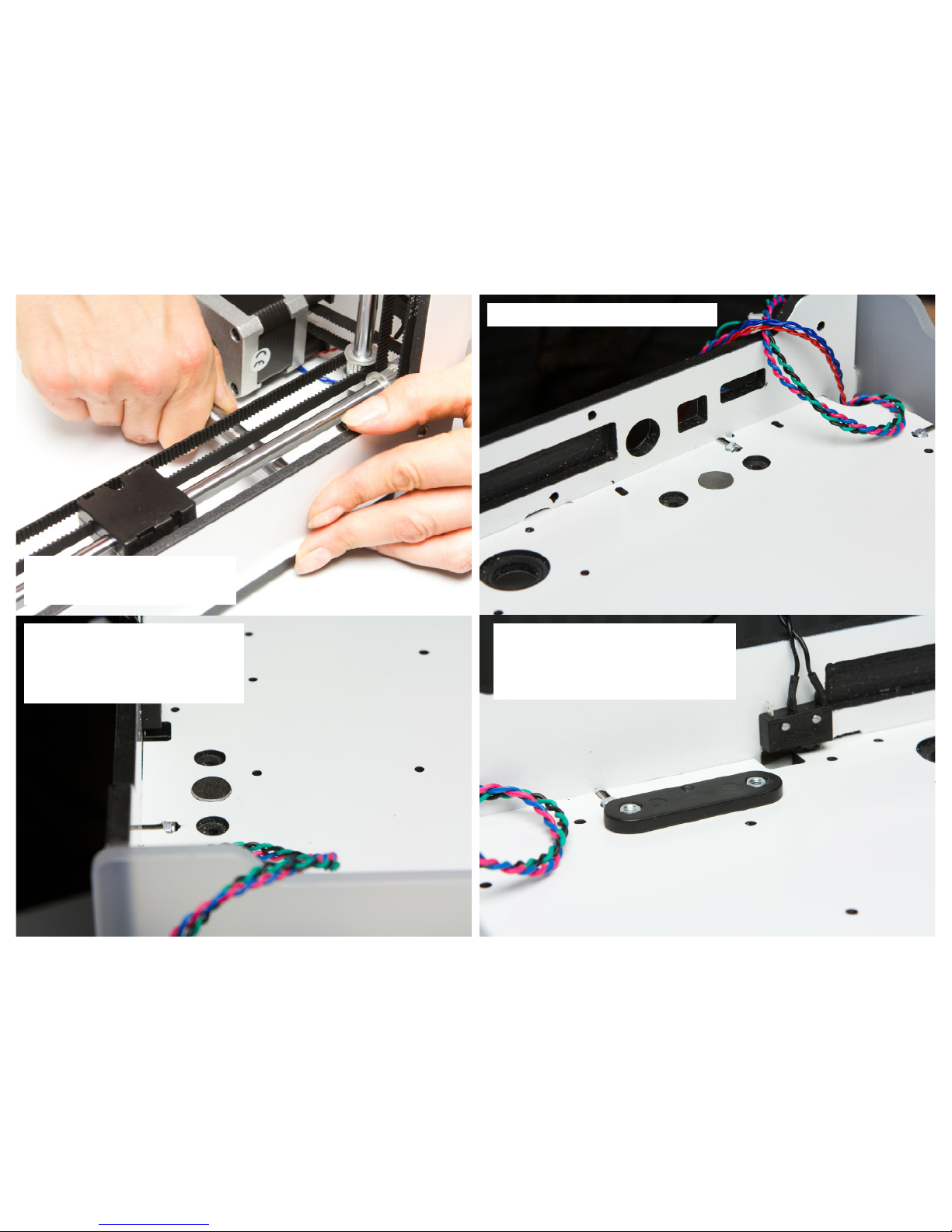
31. Attatch the motors with 8 M3x-
25mm screws.Use 8 M3 Washers
between the screwhead and the
frame. Start with the top two screws
to make it easier to position the
motor.
32. guide all the cables, both those of
the motors aswell as the endstop ones
down throught the hole in the bottom
o f the frame.
33. Repeat this entire procedure for the other motor.
19

C. Assembly of the Z-stage
20
Note: The amount of parts is always times 1, except if the
amount indicates something dierent. Make sure you have
al the parts before you start with the next step.
partnr. Part Amount
1152 Table Spring D2150 3x
1153 Print Table Base Plate
1154 Print Table Glass
1155 Print Table Heated Bed
1156 Z-shaft Cap Bottom 2x
1157 Print Table Back Cover
1159 Z-motor With Trapezoidal Lead Screw
1169 Z-linear Shaft 2x
1170 Square Flanged Linear Bearing LMK12LUU 2x
1183 Heated Bed Cable
1187 Trapezoidal Lead Nut
1200 ISO 7380 M3x8 4x
1202 ISO 7380 M3x10 14x
1204 ISO 7380 M3x16 2x
1206 ISO 7380 M3x20 4x
1213 DIN 962 Square Nut M3 A2 2x
1214 ISO 7040 nut M3 Prev. Torque A2 8x
1215 ISO 10642 M3x8 A2 4x
1216 ISO 10642 M3x20 A2 3x
1217 ISO 10642 M4x10 A2 8x
1243 Heated Bed Cable Clip
1254 Print Table Mounting Aid 3x
1256 Build Platform Glass Retainer Back 4x
1257 Knurled Nut Platform 3x
1288 Washer M6 3x
1402 Key Wrench T2.5

1. Make sure all plastic has been re-
moved from the small dibond plate.
2. Remove all jagged particles that have been left by milling.
3. To make sure the tting of the bearings
is correct. Testt the bearings in the holes
and make sure the tting is correct by
turning them fron left to right .
4. Place two nuts in the 2 T-slots of this Dibont plate.
21
C1. Z-stage

5. To build the heated bed. You need these
parts.
6. The top of the stainless steel ring comes in contact with
the aluminum and therefore should be greased with copper
7. Place the greased ring on the
adjustment screw.
8. Now remove all the foil from the aluminum plate.
22

9. position the aluminium plate in such a way
that the notch is on the right side of the middle
hole
10. Insert the adjustment screws with washers
from the bottom through the base plate.
11. Place them in the 3 appro-
priate holes.
12. Place the spring on part of the adjust-
mentscrew sticking out of the aluminium plate
23

14. Place the heated bed on the
base plate and place a glass retainer on both corners between
the heater and the spring
13. The glass retainers are screwd into
place by 4x M3x8mm screws and 4x
lock nuts.
15. Screw it down with 3x M3x20 countersunk screws.
24
12.1. Don’t forget to screw
the cable into the heated bed
orientated as in this image.

25
16. Slide the glass in the rear two
glass retainers. Click the two
front glasretainers onto the glass,
so the glass is secure.

26
17. Attach the cable guide on
the heated bed with 2xM3x10
mm screws.

27
18. Attach the trapezoidal nut
screws on the base plate and
insert the 4x M3x10 screws
from the bottom
19. Attach the ange be-
arings loosely to the base
plate with 8xM4x10mm. the
bearings need to be able to
move a little bit and will be
tightened at a later stage.

28
20. Screw a M3x20 screw in this hole
from the top. This will act as Endstop.
21. Put 4xM3 locknut into
the two cover plates.

29
23. Insert the shafts in the bottom
of the frame. Don’t slide the axles
all the way to the top
22. Remove any jagged bits left in
the milled hole in the top plate.
C2. Install Z-stage in the frame

30
24. Put the build platform in the
fram and insert the 12mm axle
through the build platform . Put
something (a piece of paper)
between the screw and the
frame to prevent scratches.
25. Fold the small Dibond
plate at an angle of 90 degrees, please note this can
be done only once.
26. Slide the Dibond plate
over the axes as follows.
31
27. Remove any dirt into the milled hole in
the top plate and slide the axle all the way
to the top.
28. Make sure the shaft is ush with the
frame, if this does not work then check
whether there is debris in the opposite hole.
if not, use a wooden plate and a hammer to
gently tap it into place.
30. Install the covers for the axes from the inside
of the housing. The notches fall into the milled
holes in the bottom plate. Fix it into place with
4xM3x10mm screws. There can’t be any gap between the black cover plate and the housing.
29. Make sure the end is ush with the frame
32
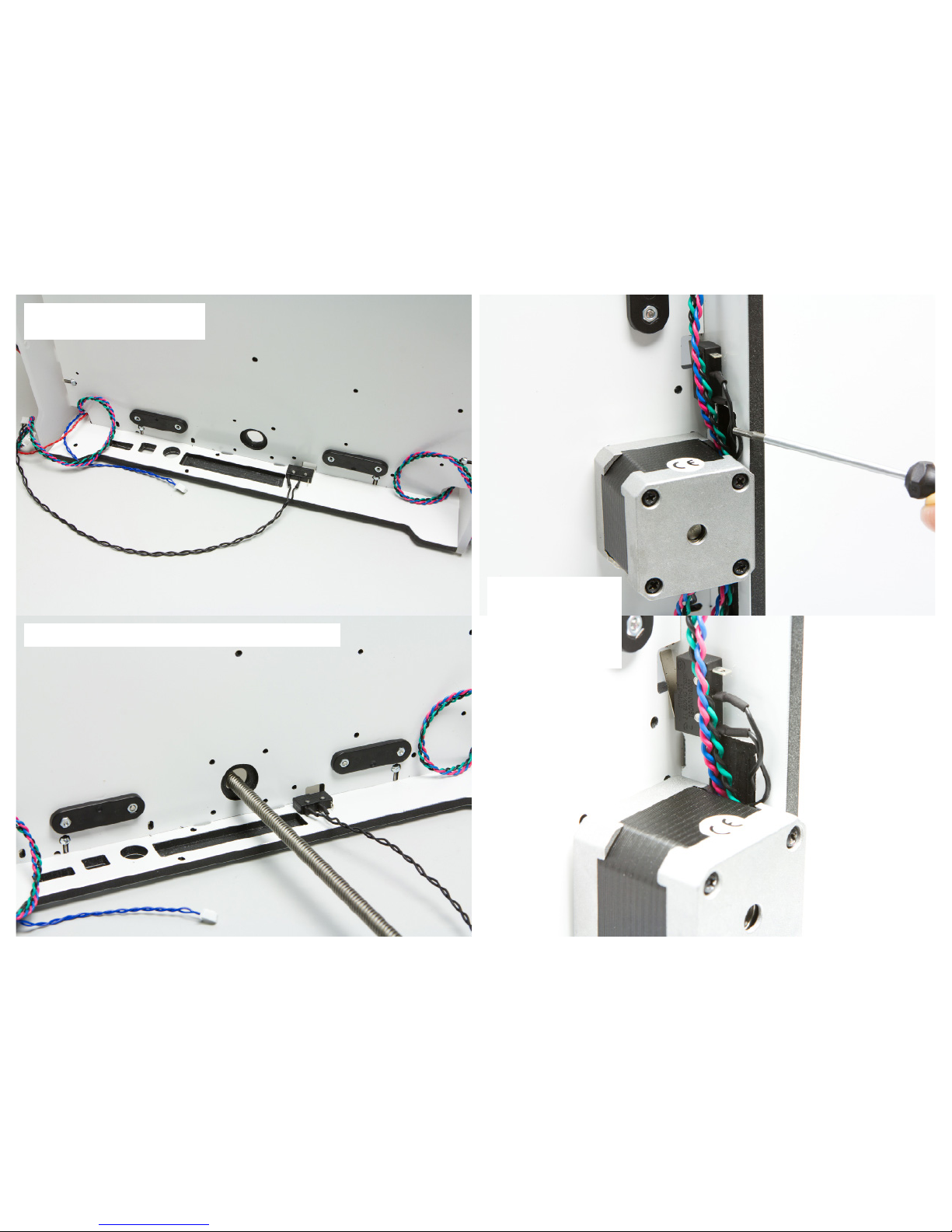
31. Make sure that both cover
plates are attached as in the picture
32. Place the Z-motor through the bottom plate and the Z table
33. Put the cable from
the motor / ends stops
behind the z-motor
through the milled slot.
Then press the Z motor in
place so it ts securely.

33
34. Now screw the
Z motor from inside
using 4x 10m3 bolts.
35. Put the frame with
Z-table upright and
tape the Dibond plate
on the top edge, this
simplies your work in
the next step.
37. Zet nu het frame
met Z-tafel rechtop
en tape voor even het
dibont plaatje aan de
bovenkant vast, dit
vermakkelijkt je werken
in de volgende stap.
36. Lift the Z-table
and place the black
calibration plugs on
the three places in the
37. Let the Z-table down
again and make sure it
is exactly on top of the
calibration plugs

34
38. Turn 1 of the 8 bolts that
hold the bearing on the Z-table. Then wiggle the Z-table
and up and down so that the
bearing can turn into the best
position.
39. Repeat until you have all
had the 4 bolts.
40. Repeat until you have all had
the 4 bolts for the other bearing
C3. Stabilize z-stage

41. Then push the Dibond cap
on the Z-table so it falls on
the bearings, press it rmly
so that the bearings are in
rmly into place
42. Then lock it in place with
2 x 16 mm bolts m3 inserted
from the bottom.
43. The heated bed cable
is guided by giving it an
extra loop through the
plate in the bottom. this
way, he can not get caught underneath the bed..
35

D. Assembly of the Material feeder
36
Note: The amount of parts is always times 1, except if the
amount indicates something dierent. Make sure you have
al the parts before you start with the next step.
partnr. Part Amount
1021 Ball Bearing 688-2RS 1x
1069 Tube Coupling Collet 1x
1143 Feeder Spring D2110 1x
1158 Reel Holder 1x
1179 Feeder Motor 1x
1201 Washer Large M3 4x
1206 ISO 7380 M3x20 1x
1207 ISO 7380 M3x25 4x
1209 Nut M3 1x
1212 Set screw M3x3
1258 Feeder Part A 1x
1259 Feeder Part B 1x
1260 Feeder Lever A 1x
1261 Feeder Lever B 1x
1263 Feeder Knurled wheel 1x
1264 Feeder Nut Holder 1x
1400 Key Wrench T1.5 1x

1. Screw the M3 socket screw
in the sleeve.
37
2. put the sleeve on the end
of the motor, with the screw
towards the end then screw
this very rmly. Make sure
that the top of the sleve and
the axle are ush.
3. Press the two parts of the
lever to each other, with the 8
mm the bearing in between

38
4. Put the lever in the
housing. Add a little green
grease between the two
parts of the lever and axle.
As a result, he turns slightly
smoother.
5. Place a hex nut in the
t-part and screw in M3x20
screw

39
6. Place the T-piece in the
housing in such a way, that
the screw pointing towards
the outside.
8. Place the tube coupler
7. Attach the spring bet-
ween the t-piece and the
lever. Sometimes it is more
convenient to combine the
spring and the t-piece and
then place the combined
parts in the extruder.

40
9. Close it by placing the other half on the extruder
10. Place The feeder
motor is on the inside of the housing
and the direct drive
to the outside of the
back plate.
11. The slide in direct
drive should point
to the side of the
machine

E. Assembly of the display
41
Note: The amount of parts is always times 1, except if the
amount indicates something dierent. Make sure you have
al the parts before you start with the next step.
partnr. Part Amount
1171 Double Flat Cable 10 Wire 2x
1202 ISO 7380 M3x10 3x
1204 ISO 7380 M3x16 4x
1214 ISO 7040 Nut M3 Prev. torque A2 3x
1244 Knob Front 1x
1245 Knob Housing 1x
1247 Display 1x
1249 Ulticontroller Board 1x
1251 Ulticontroller Electronics Cover 1x
1287 Washer M7 1x
1354 DIN 13-4 Ring M7 1x

42
1. Connect the display to the electronics as follows.
2. Slide the black latch open (towards the edge of the Ulticontroller).
3. Place the end of the at
yellow cable inside (connectors down). Make sure that
the cable is the ush into the
connector.

43
4. Push the lever back. Check whether
the at yellow cable is still sits straight in
the lock. Next remove the protective lm
from the display.
5. You can now carefully mount the
display in the opening by sliding it
in. Make sure that you do not put
(mechanical) tension on the at
yellow cable! The Ulticontroller can
be screwed from the inside of the
housing with 4x M3x16mm screws

44
6. Mount of the 4 bolts , from the inside of the machine. 7. Slide the buttoncasing in the frame-
hole in the front of the frame. the oval
hole should be orientated upward .
8. Slide the housing over knob and install the nut
and tighten up.

45
9. Connect the large at cables. (Mark the two
ends that are still hanging loose with Exp 1 and
Exp 2. (Corresponding to the appropriate output
of the electronics)
10. Put the at cable diago-
nally across the electronics,
so it is better orientated to
move out of the housing.
Make sure you don’t fold
the cables!

46
11. The cover of the display electronics
has two aps. These hold the display
pressed against the front plate. Slide
the tabs along the display inside. Then
insert the front pins in rst and then the
bottom pins.
12. Then mount the cover with 2x M12
bolts and matching lock nuts. Flat cable should come out on one side.

47
13. Finally push the button itself in
the housing on the shaft.

F. Assembly of the hot end
48
Note: The amount of parts is always times 1, except if the
amount indicates something dierent. Make sure you have
al the parts before you start with the next step.
partnr. Part Amount
1065 Linear Bearing LM6LUU 2x
1069 Tube Coupling Collet
1071 Clamp Clip 2x
1074 Print Head Thumb screw 4x
1172 Print Head Shaft X
1173 Print Head Shaft Y 1185 PT100B sensor
1186 Print Head Cable
1200 ISO 7380 M3x8 4x
1266 Bowden Tube
1268 Heater Cartridge 24V 25 W
1280 Braided Sleeve
1281 Clip 5x
1301 Integrated nozzle heater block 3mm lament
1306 Hot end holder bottom
1307 Hot end holder top
1308 Cooling Rib Hot End
1309 PTFE Isolator Coupler 3.2 mm
1310 Hot end Isolator
1311 Spring D2000
1313 Model Cooling Fan 12VDC 0.1A 2x
1320 Print Head Top
1321 Print Head Middle
1322 Print Head Bottom
1329 Dual Fan bracket
1330 Hot-End Cooling Fan 5VDC 0.08A
1348 ISO 7380 M3x4 4x
1351 ISO 4762 M2,5x10
1352 Set Screw M3x14

49
1. Make sure you have the signal
cable, Pt100 and the heater cartridge
with the tops taped together. now
slide the braided sleeve around it.
and you can remove the tape again.
2. These are the components requi-
red for the hot-end
3. Take the metal part without the
notches .This is the lower part of the
hot-end. Screw the adapter on it with
2x M3x8 screws
F1. Hot end

50
4. Lubricate the left hole (the
orientation) with copper grease. This is to prevent corrosion between aluminum and
stainless steel
5. Attach the Teon insulator
coupler, the hot-end insulator and
spring together. Place it on the
hole which you just lubricated the
copper grease.

51
6. Then place the Top Plate of
the Hot-end (with the notches
around the holes) on top. squeeze it together so you get to the
upper two screwholes and screw
it together with 2x M3x8 screws.
8. Screw the hot-end
cooling fan 5vDC onto the
back of the hot-end with
2xm2,5x10mm screws. position the fan in such a way
that the sticker is facing
the aluminium.
7. Parts hot end fan.

52
9. Place the 2 Linear Bearings
in the plastic casing in the
following fashion.
10. Snap the parts together. these
are supposed to go together
without any eord.

53
11. Guide the printhead cable
with the braided sleeve and
the Cartridgeheater and
PT100 through the plasic
casing. making sure the signal cable still sits above the
housing.
12. Now insert the
M3x14mm slug into the
messing heater block
12. Slide the cartridge
heater and the PT100
into the nozzle

54
13. Parts for the Printhead fan.
14. Attatch the fans to the
fanduct with the philipsheads
screws.
F2. bevestigen van de fans
55
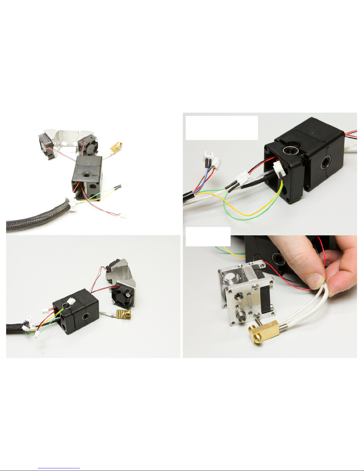
15. Guide the 2 fancables up through
the housing and attach them to the
printhead cable.
16. Attach the 2 fancables from the
fanduct to the green and yellow wires. and the fanduct from the hotend
to the pink blue cable
17. Attatch the nozzle
to the aluminium
frame.

56
18. Now turn the
hot-end isolater until
the teon isolator
part creates a gap of
at least 1 mm and the
bottom of the hotend isolater is just not
touching the messing
part.
1 mm

57
19. Attatch the fan-
duct to the alluminium frame with 4x
M3x4 screws
20. Place the 4
thumbscrews in the
plastic frame. and
tighten them down.

58
21. Make sure that the cables are not
touching the fans and are not stuck
between the housing. Now completely screw down the thumbscres
22. Make sure all the connectors are connected.
F3. kabels wegwerken

59
23. Guide the Braided sleeve around the
connectors and into the top of the frame.
so u don’t see anything sticking out.

60
24. Take the X and Y axes and
Put the X axis through bearing
in the plastic Printhead housing.
25. To prevent the axes
from bending, move
the sliderblocks all the
way to the side of the
machine. Make sure you
apply pressure to the sliderblock instead of the
supporting axes. Then
carefully click them in
place. do the same thing
for the Y axis. move it
to the side, support it
and carefully click it into
place.
F4. Printhead bevestingen in frame

61
26. Take the other side of the
bowdentube (the side with the
tape) and attach it to the direct
drive. secure everything with the
red clamp.

62
26. Attach the 5 clips between the
bowdentube and the braided sleeve.
so they run parralel together. The
braided sleve is supposed to be
underneath the bowden tube.
27. Guide the cables through the
frame and underneath the feeder
downwards until they reach the
electronics.

G. Assembly of the electronics
63
Note: The amount of parts is always times 1, except if the
amount indicates something dierent. Make sure you have
al the parts before you start with the next step.
partnr. Part Amount
xxxx Mainboard v2.1 1x
xxxx Mainboard electronics cover 1x
xxxx Spacers 3.2x6x10mm 8x
xxxx jumper 2x
xxxx cable cover 2x
xxxx ISO 7380 m3x8 2x
xxxx ISO 7380 m3x12 2x
xxxx ISO 7380 m3x30 4x
xxxx ISO 7040 Nut m3 pin torq 6x

64
1. Attach the heated-bed cable to
the electronics on the therminal
marked Heated Bed.
2. Attatch the White heater cables to therminal heater 1.

65
3. Attach the Hot-end Fan to the connector
in the middle of the electronics.
5. Now from the inside put the
4xM3x30mm screws through the
bottom plate. these will be used to
secure the electronics.
4. Check if the jumpers are attached
at the SAFETY1 en SAFETY2. if not,
attach them.

66
6. Het electronica Mainboard attaches to
the bottom. attach the electonics with
4xM3x25mm screws.
8. Attach the endstop cables to the main
board. The red cable connects at Y-stop ,
the blue one at X-stop and the black one
connects at Z-stop.
7. Attach the X,Y and Z motor cables to
the corresponding connectors on the
Electronics board. The extruder motor
cable connects at the E1 connector.

67
9. The brown and white connector
ot the heatedbed cable is the PT100,
Connect it to Temp 3. The silver sleeved
cable is the printhead PT100, connect
this to Temp 1.
10. Bevestig de Ledstrip connector in LED PWM
10. The atcables from the display
can now be connected to the electronics. Follow the numbers you put
on the cable a couple of steps back.
11. The Yellow/green
connector attaches to
the port marked Fan
PWM.
- The brown/white connector is not used at the
moment.

68
12. Now slide the
electronics coverplate into place. start
witht the pins that
t in the back plate
and then the pins
that t in the bottom
plate. Secure it with
2xM3x12 mm screws
and 2x M3 locknuts.
G1. Plaatsen van kappen

69
14. Attach both the
motor covers by
placing them in the
corners and placing
the pins in the correct
holes.
15. secure them with
2xM3x8mm screws on
the side and the back
of the machine.
13. Push the bed all the way
down by pressing just in front
of the Ultimaker 2 logo.
16. Make sure the
Heated-bed cable is
twisted when placing
the motor covers.
this is to prevent the
cable from getting
caught underneath
the bed
 Loading...