


Ultimaker 2+ Connect
Installation and user manual
EN 10/2020 v1.0 Original instructions

Table of contents
1. Safety and compliance
1.1 Safety messages 4
1.2 General safety information 4
1.3 Hazards 5
1.4 Regulatory information 6
2. Introduction
2.1 Main components 9
2.2 Specications 11
3. Installation
3.1 Unboxing 13
3.2 What's in the box? 14
3.3 Hardware installation 15
3.4 First setup 16
3.5 Firmware update 17
3.6 Install Ultimaker Cura 18
4. Operation
4.1 Touchscreen 20
4.2 Materials 21
4.3 Preparing a print with Ultimaker Cura 22
4.4 Printing with the Air Manager 24
4.5 Remove the print 25
4.6 Change the printer conguration 26
5. Maintenance
5.1 Update the rmware 28
5.2 Material handling and storage 28
5.3 Maintenance schedule 29
5.4 Replace the Air Manager lter 30
6. Troubleshooting
6.1 Error messages 32
6.2 Extrusion problems 32
6.3 Adhesion issues 33
6.4 Air Manager troubleshooting 34
7. Warranty
7.1 General 36
7.2 Conditions 36
7.3 Notication 37
7.4 Exclusions 37
7.5 Applicable law and competent court 37
Ultimaker 2+ Connect user manual 1

Disclaimer
This manual sets out the instructions on how to install and operate the Ultimaker 2+ Connect. Please read and
understand the contents of this installation and user manual carefully. Failure to read the manual may lead to
personal injury, inferior print results or damage to the Ultimaker printer or its peripherals. Always make sure that
anyone who uses this 3D printer knows and understands the contents of the manual to make the most out of
the Ultimaker printer.
Upon delivery of the product, installation shall be done in accordance with the instructions in this user manual. The
handling, storage, use, or disposal of the device are beyond our control and are for your sole responsibility. We do
not assume responsibility and expressly disclaim liability for loss, injuries, damage, or expense arising out of or in
any way connected with the handling, storage, use, or disposal of the product.
The information within this document has been collected and represented with great care and is considered
accurate. In case inconsistencies or inaccuracies are observed those are unintentional and Ultimaker welcomes to
be made aware of those. Submit your feedback to Ultimaker via ‘Submit a request’ at support.ultimaker.com.
Intended use
Ultimaker 3D printers are designed and built for fused lament fabrication with Ultimaker materials mainly within
a commercial, professional, or educational environment. The mixture of precision and speed makes Ultimaker 3D
printers very suitable for concept models, functional prototypes, and small series production.
The Ultimaker 2+ Connect, with its networking capabilities and new touchscreen, delivers single extrusion for
simple applications.
Although we achieved a very high standard in the reproduction of 3D models with the usage of Ultimaker Cura,
the user remains responsible to qualify and validate the application of the printed object for its intended use. This
is especially critical for applications in strictly regulated areas like medical devices and aeronautics. While being
an open material platform, the best results will be achieved with Ultimaker materials, as eort has been made to
match material properties with machine settings.
Ultimaker 2+ Connect user manual 2
1. Safety and compliance
1.1 Safety messages
The information provided below is applicable to the Ultimaker 2+ Connect and Ultimaker 2+ Connect Air Manager
(“Ultimaker products”).
This guide contains warnings and safety notices.
Provides additional information that is helpful to do a task or to avoid problems
Warns of a situation that may cause material damage or injuries if the safety instructions are not followed.
The following ISO warning symbols are also used:
Magnetic eld (ISO 7010-W006)
Electricity hazard (ISO 7010-W012)
Hot surface (ISO 7010-W017). This symbol is also placed on the printhead and the glass build plate of the
Ultimaker 2+ Connect
Crushing of hands (ISO 7010-W024). This symbol is also placed on the bottom panel of the Ultimaker 2+
Connect under the build plate
Pinching and entanglement hazard
Read the user manual (ISO 7010-M002). Before using this product, read the complete user manual to
learn about all its features and safety related information. This symbol is placed on the front of the
Ultimaker 2+ Connect
1.2 General safety information
• Ultimaker products shall only be used by persons that have carefully read and understood the user manual
and the safety provisions in it
• Ultimaker 3D printers generate high temperatures and have hot moving parts that can cause injury.
Never reach inside Ultimaker 3D printers while they are in operation. Always control the printers with the
touchscreen at the front or the power switch at the back
• Allow the Ultimaker 3D printers to cool down suciently before reaching inside, typically 5 minutes, unless
explicitly stated otherwise for certain (maintenance) processes
• Do not change or adjust any parts of the product unless the change or adjustment is authorized by Ultimaker
• Do not store items inside Ultimaker products
• Ultimaker products are not intended for use by persons with reduced physical and/or mental capabilities, or
persons with lack of experience and knowledge, unless they are supervised or have been given instructions
concerning the use of the appliance by a person responsible for their safety
• This product is not intended for use by children. When using this product, children should be under constant
supervision of an adult responsible for their safety. Maintenance actions shall only be performed by an adult
• Do not change the lter of the Air Manager while the fan is in operation. Turn o the printer to make sure the
fan cannot start unexpectedly
Ultimaker 2+ Connect user manual 4
1.3 Hazards
Electrical safety
The external power supply should not be tampered with. If due to a defect replacement is needed, it should only be
replaced by the original type
A mains socket with protective earth/ground terminal must be used. Make sure that the building installation
has dedicated means of over-current and short-circuit protection. Please use a circuit breaker with a current
rating not exceeding 16A. For more information, please visit our website for the CB-certicate.
Always unplug the product before performing maintenance or modiciations, unless explicitly stated otherwise
for certain (maintenance) processes.
Mechanical safety
The Ultimaker 2+ Connect contains moving parts. Install the (optional) Ultimaker 2+ Connect Air Manager to ensure
a protective barrier from moving parts during operation, especially if operated near children.
Pinching and entanglement hazard. Do not reach into the top area of the printer during operation due to a
pinching hazard. Do not lean over the printer during operation due to risk of entanglement of hair, jewelry,
and/or scarfs. This may cause minor pain, but no signicant injury to the user is expected from pinching or
entanglement by the drive belts.
Crusing or pinching hazard. The force of the build plate is limited but may cause minor injury, so stay out of
the reach of the build plate during operation.
Always unplug the product before performing maintenance or modications, unless explicitly stated otherwise
for certain (maintenance) processes.
Risk of burns
Hot surface hazard. There is a potential risk of burns: the print heads of the Ultimaker 3D printers can reach
temperatures above 200 °C, while the heated bed can reach temperatures above 100 °C. Do not touch either of
these parts with your bare hands. This symbol is placed on the print head and on the glass build plate to warn
the user about this risk.
Always allow the product to cool down suciently before performing maintenance or modications, unless
explicitly stated otherwise for certain (maintenance) processes.
Emission hazard
During 3D printing, , Ultrane Particles (UFPs), Volatile Organic Compounds (VOCs), and other chemical
substances may be emitted. Above certain concentrations (Threshold Limit Values, TLV), these emissions
can pose a risk. Concentrations are inuenced by the lament and adhesive used, print conditions (e.g. print
temperature), room volume, Air Exchange Rate (AER), and number of printers in a room.
Ultimaker products are designed for use with Ultimaker materials and are open for use with materials from
third-party suppliers.
Ultimaker 2+ Connect user manual 5
Safe use information for Ultimaker materials. Ultimaker materials can be printed safely without any
ltering using the recommended temperatures and settings in a well-ventilated area (minimum refresh rate
or AER of 1.8 for a room size of 30.6 m3). When multiple Ultimaker 3D printers are operated in a contained
environment, concentrations of UFPs and/or VOCs will increase. Depending on the specic situation, please
consider other safety measures, such as an Air Manager to control UFPs, or a separate lter, cabinet, and/or
dedicated ventilation system.
Safe use information for third-party materials. Make sure to check with your material supplier whether
additional risks and safety measures apply. Additional safety measures may include a lter for the safe usage
of such materials. Please take the relevant information provided by the supplier of such lament/material
into account at all times for safe operation. Please check the safety data sheet of each specic material for
information. Ultimaker cannot be held responsible for any adverse eects from the use and/or performance of
third-party materials.
For classrooms and other locations where children may be present during printing, the use of Ultimaker PLA
and the addition of the Ultimaker 2+ Connect Air Manager are recommended.
Magnetic eld
Staticmagneticeldhazard.Due to the static magnetic eld caused by the magnets in the printer and in the
front enclosure of the Ultimaker 2+ Connect Air Manager, keep a distance of at least 4 cm between any implanted
electronic medical devices and implants containing ferromagnetic materials.
Personal protective equipment
The following items are recommended for working safely with the Ultimaker 2+ Connect, especially for performing
maintenance actions:
• Tweezers. These are required for safely removing material residue from the tip of the nozzle
• Pliers. When cleaning the inside of the nozzle with the hot and cold pull procedure, hold the lament with pliers
to prevent damage to your hands in case the material breaks
• Thermal gloves. It is recommended to wear thermal gloves while cleaning or replacing the nozzle as the nozzle
will be hot during these procedures
1.4 Regulatory information
Ultimaker products are compliant with the following directives:
• Machinery Directive 2006/42/EC
• Electromagnetic Compatibility (EMC) Directive 2014/30/EU
• Radio Equipment Directive (RED) 2014/53/EU
• Restriction of Hazardous Substances (RoHS) Directive 2011/65/EU
• Directive 2002/96/EC on waste electrical and electronic equipment (WEEE)
• Regulation (EC) 2007/2006 (Registration Evaluation Authorization of Chemicals, REACH)
The risks of this product have been assessed in accordance with ISO 12100. The EC declaration of conformity
can be found on our website. The standards that have been used for testing our products include but are not
limited to IEC 62368-1.
EMC
Warning: This is an EMC Class A device. Operation of this equipment in a residential environment could
cause radio interference.
Ultimaker 2+ Connect user manual 6

FCC / ISED regulatory notices
• Modicationstatement.Changes or modications not expressly approved by Ultimaker could void the user’s
authority to operate the equipment
• Wireless notice. This device complies with FCC/ISED radiation exposure limits set forth for an uncontrolled
environment and meets the FCC radio frequency (RF) Exposure Guidelines and RSS-102 of the ISED radio
frequency (RF) Exposure rules. This transmitter must not be co-located or operating in conjunction with any
other antenna or transmitter
• FCC Class A digital device notice. This equipment has been tested and found to comply with the limits for a
Class A digital device, pursuant to part 15 of the FCC Rules. These limits are designed to provide reasonable
protection against harmful interference when the equipment is operated in a commercial environment. This
equipment generates, uses, and can radiate radio frequency energy and, if not installed and used in accordance
with the instruction manual, may cause harmful interference to radio communications. Operation of this
equipment in a residential area is likely to cause harmful interference in which case the user will be required to
correct the interference at their own expense
Ultimaker 2+ Connect user manual 7
2. Introduction
2.1 Main components
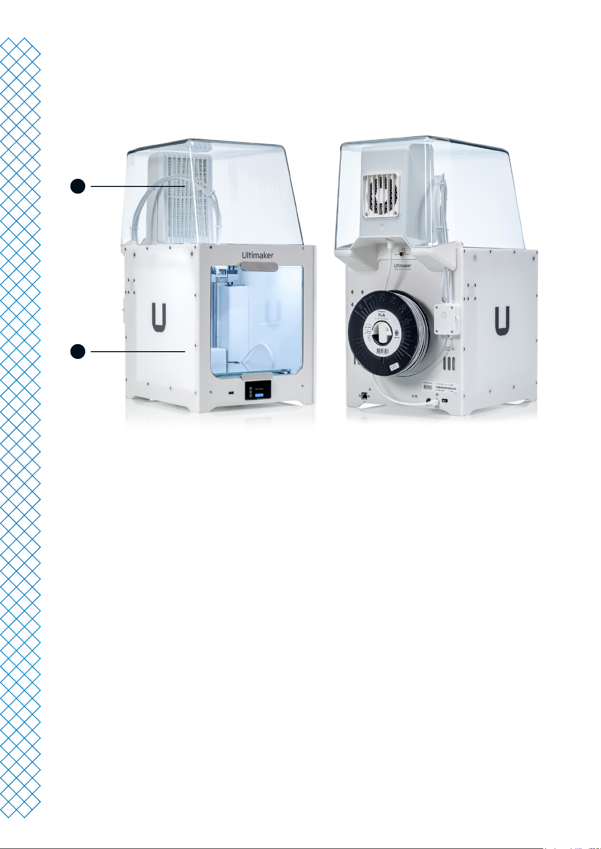
Ultimaker 2+ Connect with Air Manager
1
2
1. Air Manager
2. Ultimaker 2+ Connect
Ultimaker 2+ Connect user manual 9
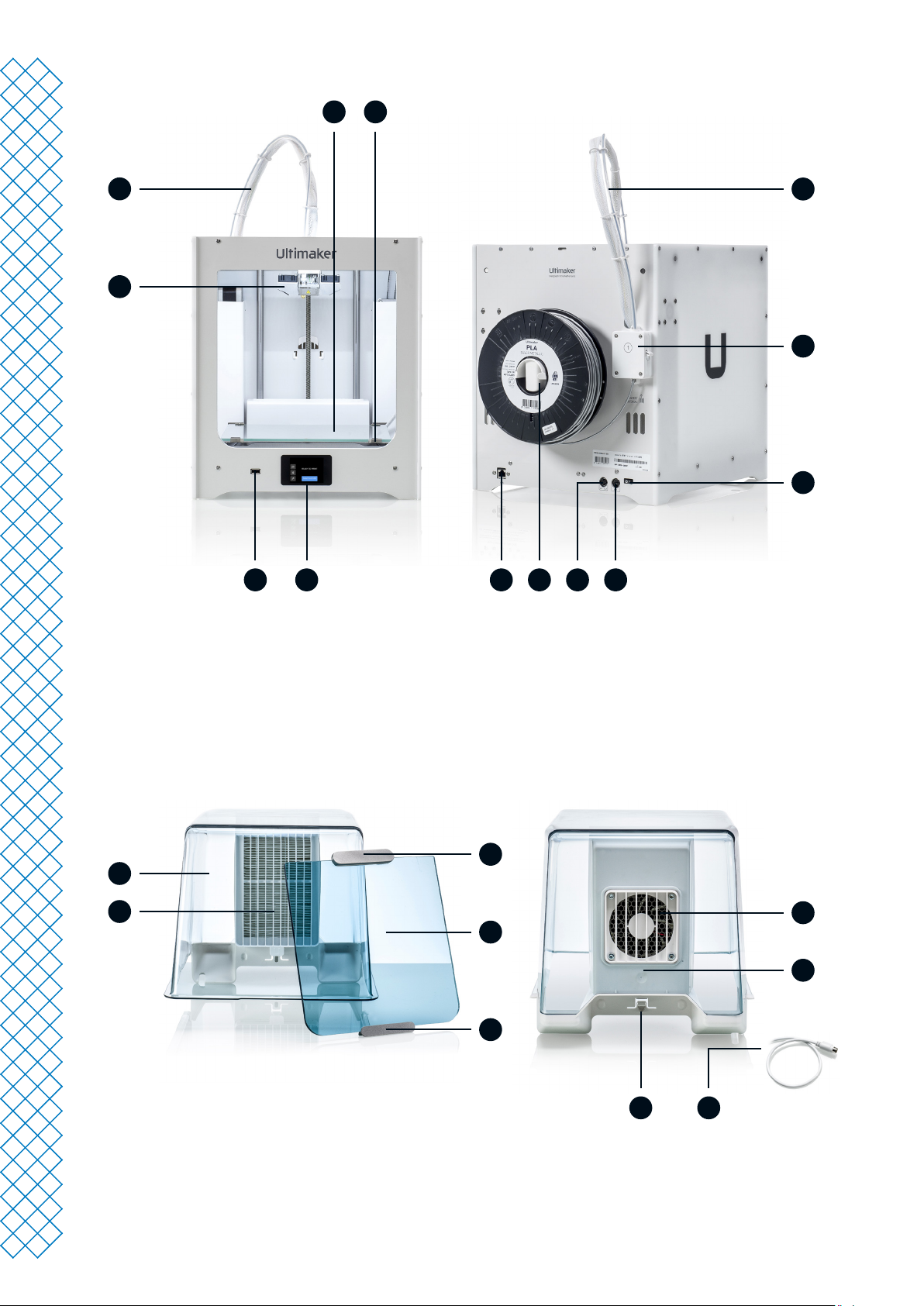
Ultimaker 2+ Connect
3 4
2
1
6
1. Print head
2. Print head cable
3. Build plate
4. Build plate clamps
5
5. Touchscreen display
6. USB port
7. Bowden tube
8. Feeder
1013 12
11
9. On/o button
10. OUT port
11. Power socket
12. Spool holder
13. Ethernet port
7
8
9
Air Manager
2
1
1. Filter
2. Air Manager cover
3. Handle
4. Front enclosure
5. Hinge prole
6. Fan
3
6
4
7
5
89
7. Filter housing
8. Air Manager cable
9. Air Manager release clip
Ultimaker 2+ Connect user manual 10
2.2 Specications
Properties Technology Fused lament fabrication (FFF)
Print head Single extrusion print head with swappable nozzles
Build volume (XYZ) 223 x 220 x 205 mm (8.7 x 8.6 x 8 in)
Nozzle diameter 0.4 mm (included)
0.25 mm, 0.6 mm, 0.8 mm (sold separately)
Layer resolution 0.25 mm nozzle: 150 - 60 micron
0.4 mm nozzle: 200 - 20 micron
0.6 mm nozzle: 300 - 20 micron
0.8 mm nozzle: 600 - 20 micron
XYZ resolution 12.5, 12.5, 2.5 micron
Nozzle temperature 180 - 260 °C (350 - 500 °F)
Build speed < 24 mm3/s
Build plate Heated glass build plate
Build plate temperature 20 - 110 °C (60 - 230 °F)
Operating sound < 50 dBA
Connectivity Wi-Fi, Ethernet, USB port
Physical dimensions Dimensions (with Bowden tube and
spool holder)
Net weight 10.3 kg (22.7 lbs)
Ambient conditions Operating ambient temperature 15 - 32 °C (32 - 90 °F)
Non - operating (storage) temperature 0 - 32 °C (32 - 90 °F)
Relative humidity 10 - 90% RH non-condensing
Air Manager Filter technology EPA lter
Filter eciency Up to 95% of UFPs
Filter replacement Recommended every 1,500 print hours (approx. 1 year)
Front enclosure Separate front enclosure included with the Air Manager
Electrical requirements Voltage 100 - 240 V AC
Frequency 50 - 60 Hz
Power Max. 221 W
Software Ultimaker Cura Our free print preparation software
Ultimaker Digital Factory Our online printer and print job management solution
Supported OS Windows, MacOS, Linux
Warranty Warranty period 12 months
342 x 460 x 580 (13.5 x 18.1 x 22.8 in)
Ultimaker 2+ Connect user manual 11

3. Installation

3.1 Unboxing
Ultimaker 2+ Connect
The Ultimaker2+ Connect comes in reusable, durable packaging, specially designed to protect your 3D printer.
Follow the steps below properly to unpack your Ultimaker printer.
It is recommended to remove the packaging with the box placed on the oor for safety. Please retain all
packaging for warranty purposes.
When placing the printer on a shelf or table, take proper measures to prevent the printer from falling.
1. Remove the plastic locking clips from the lower section of the box
2. Holding the handles, lift the upper section of the box, and place it aside
3. Take the quick start guide, safety and warranty information booklet, accessory box, and spool of lament o
the upper cardboard piece
4. Remove the upper cardboard section and four foam pieces
5. Carefully lift the Ultimaker 2+ Connect out of the bottom cardboard section and foam pieces
6. Place the printer on a at surface
Air Manager
Please retain all packaging for warranty purposes.
1. Open the box at the top and remove the foam piece
2. Take out the box with the lter housing and Air Manager cable
3. Lift the foam piece that holds the front enclosure and lter
4. Lastly, take the Air Manager cover out of the box and remove the cardboard piece
Ultimaker 2+ Connect user manual 13

3.2 What's in the box?
Ultimaker 2+ Connect
The Ultimaker 2+ Connect is supplied with several hardware accessories. Check if all these items are
included before continuing:
Accessories
1. Glass plate
2. Spool holder
3. Power adapter and cable
4. Ethernet cable
5. USB stick
6. Calibration card
7. 0.4 mm nozzle
Consumables
8. PLA Silver Metallic 750 g
9. Glue stick
10. Oil
11. Grease
Tools
12. Hex screwdriver 2 mm
13. Hex key 2.5 mm
14. Nozzle wrench
15. Print head calibration aid
Documents
16. Quick start guide
17. Safety and warranty information
Air Manager
The Air Manager is shipped in several parts, which can be installed in a few easy steps.
Check if all these items are included before continuing:
1. Filter housing
2. Filter
3. Cover
4. Front enclosure
5. Air Manager cable
6. Quick start guide
Ultimaker 2+ Connect user manual 14

3.3 Hardware installation
Ultimaker 2+ Connect
1. Insert the spool holder into the back panel and push until it snaps into place
2. Open the front build plate clamps to insert the glass plate
3. Slide the glass plate into the rear build plate clamps, then close the front clamps
The warning icon (hot surface) on the glass plate should face upwards.
4. Connect the power cable to the printer with the at side facing down and the other end to a power outlet
A mains socket with protective earth/ground terminal must be used. Make sure that the building installation
has dedicated means of over-current and short-circuit protection. Please use a circuit breaker with a current
rating not exceeding 16A.
If you also have an Air Manager, rst install the Air Manager before connecting the power cable.
Install the spool holder Place the glass build plate Connect the power cable
Air Manager
Ensure the Ultimaker 2+ Connect is turned o before installing the Air Manager.
1. Align the lter housing with the back of the Ultimaker 2+ Connect
2. Guide the Bowden tube and print head cable into the slot
3. Push down on the lter housing until it clicks rmly into place
4. Gently push the lter completely into the lter housing, with the tab facing down
5. Place the cover over the lter housing and align it with the top panel; ensure there are no gaps between the
cover and the printer
6. Connect the Air Manager cable to the port at the back of the Air Manager and secure with the clip
7. Guide the Air Manager cable around the left side of the spool holder
8. Plug the cable into the OUT port at the back of the Ultimaker 2+ Connect
9. Take the front enclosure and place the hinge prole on the front panel
10. Push the handle against the panel; the magnet will hold the front enclosure in place
The Ultimaker 2+ Connect and Air Manager must be positioned out of direct sunlight when in use. Ensure there
is at least 10 cm of free space at the back of the Air Manager for unrestricted airow.
Align the lter housing Place the Air Manager cover Install the front enclosure
Ultimaker 2+ Connect user manual 15

3.4 First setup
After installing the hardware accessories, set up the printer for rst use. Turn on the printer with the power switch
at the back. After booting up, you will see the home screen. This displays your printer status, and allows you to
quickly navigate to the Materials, Settings or Maintenance menus.
It is possible that the Ultimaker 2+ Connect shows a rmware upgrade screen when it boots up for the rst
time. If this is the case, go to ultimaker.com/rmware, select the Ultimaker 2+ Connect, and download the
rmware le. Save this le to the root directory of a USB stick. While the device is powered on, insert the USB
stick to automatically start the rmware update.
Level the build plate
To get the correct distance between the build plate and the nozzle, you need to level the build plate. The Ultimaker
2+ Connect utilizes a three-point bed level procedure. This must be done before using the Ultimaker 2+ Connect for
the rst time and then periodically.
Select the Maintenance menu and navigate to Level build plate. Follow the instructions on the display.
If you have installed the Air Manager, remove the front enclosure until this procedure is nished.
1. Wait for the Ultimaker 2+ Connect to move the print head and build plate to the start position
2. Place the calibration card between the nozzle and build plate. Adjust the thumb wheel under the build plate at
the back until you feel some resistance when moving the card. Select Done adjusting to continue
The print head will move to the next position. Keep hands clear of the build volume until the print head and
build plate have stopped moving. The printer will beep when it is safe to continue.
Do not apply force to the build plate while placing the calibration card, as this will lead to leveling inaccuracies.
3. Place the calibration card under the nozzle again and adjust the front-right thumb wheel until you feel some
resistance on the card. Select Done adjusting to continue
4. Repeat this for the front-left thumb wheel
5. As a nal step, the printhead will return to the rst point. Fine-tune the leveling, and check if you still feel the
same resistance on the calibration card at the back of the build plate, or adjust the thumb wheel until you do
The build plate is now leveled correctly for an optimal adhesion of the rst layer.
Load material
Before you can start printing on the Ultimaker 2+ Connect, you need to load material into the printer. For the rst
use, it is recommended to use the spool of PLA that came with the Ultimaker 2+ Connect.
Select the Materials menu and navigate to Load material. Follow the instructions on the display.
1. Select the material type and wait for the nozzle to heat up
2. Unpack the material and cut o the end, ensuring a short, sharp tip
3. Place the spool on the spool holder with the material in counterclockwise direction
Straighten the end of the material so it can easily enter the feeder.
4. Open the feeder lever, insert the lament into the feeder, and push it through to the print head
5. Close the feeder lever
6. Conrm that the spool is loaded and wait for the material to extrude from the nozzle
Ultimaker 2+ Connect user manual 16

Network connection
The Ultimaker 2+ Connect can connect to a local area network, using either Wi-Fi or Ethernet.
Select the Settings menu and navigate to Network conguration. Follow the instructions on the display.
Set up Wi-Fi
To connect your Ultimaker 2+ Connect to a wireless network, you will need a computer or a smartphone. Select
Connect via Wi-Fi to start the Wi-Fi setup and follow the steps on the touchscreen:
1. Wait until your printer has created a Wi-Fi hotspot. This may take a moment
2. Use a computer or smartphone to connect to the printer. The name of the Wi-Fi network is shown on the
display of the printer
3. A pop-up will appear on the display of your computer or smartphone. Follow the steps to connect the printer to
your local Wi-Fi network. The pop-up will disappear when you have completed these steps
If the pop-up does not appear, open a browser and enter the IP address shown on the display.
Within some network environments, the Ultimaker 2+ Connect may experience diculties connecting
wirelessly. When this happens, repeat the Wi-Fi setup from another computer or smartphone.
4. Go back to the Ultimaker printer and select Continue when you have completed the Wi-Fi setup
Connect via Ethernet
You can set up a wired network connection by performing the following steps:
1. Select Connect via LAN in the Network connection menu
2. Connect one end of an Ethernet cable to the Ethernet port at the back of the printer
3. Connect the other end of the cable to a network source (router, modem, or switch)
4. Wait for the printer to conrm the connection
The Ultimaker 2+ Connect does not feature local network printing. Instead, use the Digital Factory to send print
jobs via the cloud, and to monitor your printer remotely.
3.5 Firmware update
If connected to a network, the Ultimaker 2+ Connect will check if the latest rmware is installed. If a newer version
is available, it will download the latest rmware and install it. This process may take several minutes to complete.
You will only be prompted to install the latest rmware if the printer is connected to a network and an older
rmware version is detected. If the printer is not connected to the network, go to ultimaker.com/rmware to
check if an update is available.
Ultimaker 2+ Connect user manual 17

3.6 Install Ultimaker Cura
After successfully setting up your printer, install Ultimaker Cura – Ultimaker’s free print preparation software on
your computer. You can download Ultimaker Cura at ultimaker.com/software.
For more information about Ultimaker Cura and system requirements, please consult the Ultimaker Cura user
manual at support.ultimaker.com.
After downloading, run the installer to complete the installation of Ultimaker Cura. When opening Ultimaker Cura
for the rst time, you will be asked to select your 3D printer. Select the Ultimaker 2+ Connect prole, and you are
ready to go. You can now directly connect to the printer and start using Ultimaker Cura.
For best printing results, always use the latest version of Ultimaker Cura.
Ultimaker Digital Factory
The Ultimaker 2+ Connect benets from integration with Ultimaker Digital Factory. To make the most out of your
Ultimaker printer, you must rst associate the printer with your Ultimaker Account.
Sign in or create your Ultimaker Account to utilize the Ultimaker 2+ Connect network functionality. This
procedure runs in the web browser of your computer. After signing in, your browser shows the Ultimaker Digital
Factory environment.
For more information on the Ultimaker Digital Factory, visit digitalfactory.ultimaker.com.
Congure the Ultimaker 2+ Connect
Start Ultimaker Cura and follow the onboarding procedure. Select the Ultimaker 2+ Connect from the list of printers
connected to your network. If the printer is not connected, select it from the list of non-networked printers.
To add the Ultimaker 2+ Connect to an existing Ultimaker Cura set-up, select the Printers tab and choose Add printer.
Select the Ultimaker 2+ Connect in the Digital Factory Add the Ultimaker 2+ Connect in Ultimaker Cura (non-networked)
Ultimaker 2+ Connect user manual 18

4. Operation

4.1 Touchscreen
You can control the Ultimaker 2+ Connect by using the touchscreen at the front of the printer.
Interface
The main menu oers three options, represented by the following icons:
Materials. This menu shows which material is currently loaded. It also oers the options to change, load, or
unload material, or select a dierent material type.
Settings. In this menu, you can update the rmware, connect to the Digital Factory, and change settings for
the frame lighting.
Maintenance. In the maintenance menu, you can manually set the nozzle temperature and move the build
plate, for example for troubleshooting purposes. Additionally, this menu oers the build plate leveling process
and a diagnostics option.
Scroll through the sub-menus by using the up and down arrows on the right side. The number of pages is shown in
the middle. Select the left arrow icon in the top-left corner to exit the menu and return to the main menu. Once you
have started a process, such as Unload material, instructions will be provided on the display. If necessary, select the
X icon in the top-right corner to abort the process.
Ultimaker 2+ Connect user manual 20

4.2 Materials
Material compatibility
The Ultimaker 2+ Connect supports all Ultimaker build materials that are currently available, of which most can be
printed with the 0.25, 0.4, 0.6, and 0.8 mm nozzle sizes.
All Ultimaker materials have been extensively tested and have optimized proles in Ultimaker Cura to ensure
the best print results. Therefore, it is advised to use one of the default proles in Ultimaker Cura for the
highest reliability.
Print recommendations
Each material requires dierent settings for optimal results. When using Ultimaker Cura to prepare your model,
these settings are automatically set correctly if the correct nozzle size and material are selected.
It is recommended to apply a thin layer of glue (using the glue stick from the accessory box) or an adhesion sheet
to the glass build plate before starting a print. This will ensure that your print adheres reliably to the build plate,
and also prevents the glass build plate from chipping when removing prints.
Chipped pieces of the glass plate stuck to the print after removing can cause cuts. Always use the
recommended adhesion method.
The warning icon on the glass plate should face upwards. This side is best for printing and
ensures optimal adhesion
For detailed instructions on which settings and adhesion method to use per material, take a look at the material
manuals and adhesion recommendations on the Ultimaker website.
3D printing thermoplastics may result in the release of ultrane particles (UFPs) and volatile organic
compounds (VOCs) depending on the laments used and settings of the 3D printer. In case UFP emissions are
unknown or are likely to be signicant, it is advised to use the Air Manager with the Ultimaker 2+ Connect or
use the printer in a well-ventilated room. Ensure that the laments are printed at the advised temperatures;
too high printing temperatures will cause additional emissions. Other measures needed to further control
emissions strongly depend on the specic conditions under which the printer(s) are used.
Ultimaker 2+ Connect user manual 21

4.3 Preparing a print with Ultimaker Cura
Interface
1 2 3 4
9
5
678
After adding the Ultimaker 2+ Connect in Ultimaker Cura, the main interface will become visible. Here is an
overview of the user interface (UI).
UI elements:
1. Open le
2. Printer selection panel
3. Stages
4. Conguration panel
5. Print settings panel
6. Action panel
7. 3D viewer
8. Camera position tool
9. Adjustment tools
The Ultimaker Cura workow is arranged in three stages, seen at the top of the interface. These are the prepare,
preview, and monitor stages.
Ultimaker 2+ Connect user manual 22

Prepare stage
Load a model and prepare it for slicing in the prepare stage of Ultimaker Cura.
1. Load the model(s) by clicking the ‘open le’ folder icon
2. In the conguration panel, select the material type you wish to print with
3. Use the adjustment tools to position, scale, and rotate the model as desired
The adjustment tools are visible when a model is loaded and selected on the 3D viewer.
4. Select your desired settings (prole, layer height, inll, support and build plate adhesion) in the
print settings panel
5. When satised with your print settings and print strategy, press the Slice button on the action panel
6. When slicing is complete, the action panel will now direct you to the preview stage
For more information about the prepare stage and the available settings in the custom menu, see the
Ultimaker Cura support pages.
Preview stage
The preview stage allows you to see exactly how your model will be printed. Use the dierent color schemes to get
various information about your model. You can view the dierent line types, dierentiate inll from skin, or use the
X-ray view to detect gaps within your model.
When satised with your model print preview, the action panel guides you to print over the network if connected to
a networked Ultimaker 2+ Connect.
Alternatively, you can save the le to a USB for printing with oine printers.
For more information on the preview stage, see the Ultimaker Cura support pages found on the Ultimaker website.
Monitor stage
The monitor stage utilizes the Ultimaker Digital Factory functionality so you can easily monitor the status of your
networked Ultimaker printer.
When printing on a networked Ultimaker printer, you can send your print jobs from Ultimaker Cura to the printer
via the cloud. The status of the printer will change to Printing, and you can begin to track the print’s progress. You
can also queue multiple print jobs and view them in the print queue.
Ultimaker 2+ Connect user manual 23

4.4 Printing with the Air Manager
The optional Ultimaker 2+ Connect Air Manager is designed to simply and eectively increase user safety. The Air
Manager consists of the top cover, lter, and front enclosure. Proper use of the Air Manager minimizes the emission
hazards related to UFPs caused by 3D printing materials.
The Air Manager is highly recommended in classrooms, when printing with materials that emit signicant
amounts of UFPs, or in locations with multiple 3D printers.
With a connected Air Manager, the Ultimaker 2+ Connect is enhanced with the following features:
• UFPltering. The Air Manager encloses the top and front of the Ultimaker 2+ Connect and ensures an inside-
out airow. The air passes through an E10 lter whereby ultrane particles (UFPs) get trapped
• Physical barrier. The enclosed top and front prevent users from reaching into the machine during operation
and ensures particles from the environment do not inuence the print result
The Air Manager will only work properly if all components are installed correctly. Ensure there are no gaps
between the lter housing, cover, and the printer. The front enclosure must be installed when the Air Manager
fan is running. Ensure that the Air Manager cable is securely connected and the fan is spinning during a print.
When a print has nished, wait until the printer has completely cooled down. This will allow sucient time to
lter all particles from the printing process. Then remove the front enclosure so you can take the nished print
from the build plate.
When removing the front enclosure from the Ultimaker 2+ Connect, it can be placed on top of the Air Manager.
The shape of the front of the Air Manager cover aligns with the hinge prole of the front enclosure.
Ultimaker 2+ Connect user manual 24

4.5 Remove the print
Once your 3D print is nished it must be removed from the build plate. There are several methods to do this.
When using a brim, be aware of the danger of cutting yourself when removing the print from the build plate.
Use a deburring tool to remove the brim once the print is taken from the build plate.
Always use the recommended adhesion method. Printing directly on the glass with certain materials can cause
the build plate to chip. Chipped pieces of the glass plate stuck to the print after removing can cause cuts.
Wait for cooldown
If you printed directly onto the build plate, simply allow the build plate and the print to cool down after printing.
The material will contract as it cools, allowing you to easily remove the print from the build plate.
The heated bed can reach temperatures of over 100 ºC. Do not remove the print or the glass build plate from
the printer until the printer has cooled down. The display of the Ultimaker 2+ Connect will indicate when it is
safe to remove the print or build plate.
Use a spatula
If your print is still adhered to the build plate after cooling, you can use a spatula to remove the print.
Use a spatula with rounded corners to avoid cutting yourself on sharp edges.
Place the spatula under the print, parallel to the build plate, and apply a small amount of force to remove the print.
A spatula can also be used to carefully remove remaining parts of the print from the build plate, such as the brim
or support structures.
Take the build plate out of the printer to avoid damaging the build plate clamps.
Use water
Remove the build plate from the printer when the display indicates it is safe to do so. Run cool tap water over the
bottom of the plate to cool it quickly. Due to the contraction of the material, the print will easily pop o the plate.
Alternatively, you can run lukewarm water over the print side of the plate to dissolve the glue.
Conrm removal
Once the print has been removed and the build plate is placed back in the printer, conrm the print removal on the
display of the Ultimaker 2+ Connect. This will allow the next print job to start.
If the Ultimaker 2+ Connect is connected to the network and utilizing the Digital Factory, queued print jobs can
start remotely. To prevent damage to the printer, do not conrm the print is removed until the build plate is
clear and placed back in the printer.
If necessary, clean the glass build plate and apply a new layer of glue before starting the next print.
Ultimaker 2+ Connect user manual 25

4.6 Change the printer conguration
Change material
Materials can be changed easily on the Ultimaker 2+ Connect.
Select the Materials menu and navigate to Change material. Follow the instructions on the display.
1. Select the new material type. If you want to load a new spool of the same material, select Yes. If you are
changing to a dierent material, select No and choose the new material type on the next screen
2. Wait for the nozzle to heat up
3. Open the feeder lever, pull the material out through the Bowden tube, and remove the spool
from the spool holder
4. Place the new spool on the spool holder with the material in counterclockwise direction
Straighten the end of the material so it can easily enter the feeder.
5. Insert the lament into the feeder and push it through to the print head
6. Close the feeder lever
7. Conrm that the spool is loaded and wait for the material to extrude from the nozzle
8. Conrm and wait for the nozzle to cool down after this procedure
Change the nozzle
The Ultimaker 2+ Connect has a heater block with easily swappable nozzles. A 0.4 mm nozzle is already installed,
and an extra 0.4 mm nozzle is included in the accessory box. Other compatible nozzle sizes include 0.25 mm, 0.6
mm, and 0.8 mm and can be purchased separately. To change the nozzle, use the 7 mm wrench that is included
in the accessory box.
Before removing the nozzle, perform a cold pull to remove material residue from the inside of the nozzle.
1. Remove the material from the print head
The lament only has to be partially unloaded, until it is visible above the print head. Use the Change material
procedure or raise the nozzle temperature via the Maintenance menu and unload the lament manually.
2. Place the print head in the middle of the gantry for easy access
3. Set the nozzle temperature to 100 ºC
4. Use the 7 mm wrench to unscrew the nozzle from the heater block, in a clockwise direction
The nozzle is warm. Take proper measures to catch the nozzle when it is loosened from the heater block.
Protective (thermal) gloves are advised.
5. Select the desired nozzle and manually screw it into the heater block until it is hand-tight
Be careful, as the heater block is still warm. Protective (thermal) gloves are advised.
6. Use the wrench to fully tighten the nozzle
If a dierent size nozzle was installed, ensure to select the corresponding nozzle size in Ultimaker Cura to
prepare the next print job.
Ultimaker 2+ Connect user manual 26

5. Maintenance

5.1 Update the rmware
Periodically, a new version of the Ultimaker 2+ Connect rmware is released. To ensure that your Ultimaker 2+
Connect is equipped with the latest features, it is recommended to keep the rmware updated to the latest version.
Update over the network
If the Ultimaker 2+ Connect is connected to a network, it automatically checks for available rmware updates. When
a new rmware is available, the printer will prompt you to download and install it via the touchscreen interface.
Alternatively, check for updates manually by navigating to Settings → Update rmware.
Do not power o the printer during the rmware installation.
Update using a USB stick
If your Ultimaker 2+ Connect is not connected to a network, you can update to the latest rmware via USB.
The rmware les are found on the Ultimaker website:
1. Navigate to ultimaker.com/rmware, and select your printer
2. Download the rmware image and store it in the root directory of your USB stick
3. Insert the USB stick into the USB port of the printer
4. Go to Settings → Update rmware and select the new rmware from the USB device
Do not power o the printer during the rmware installation.
5.2 Material handling and storage
Opened material spools must be stored properly when not in use. If material is stored incorrectly, it may aect its
quality and usability.
The optimal storage temperature for PLA, Tough PLA, Nylon, CPE, CPE+, PC, TPU 95A, and PP is between -20 and
+30 °C. For ABS, the advised temperature is between 15 and 25 °C. Furthermore, a relative humidity of below
50% is recommended for TPU 95A and PP. If these materials are exposed to a higher humidity, the quality of the
material can be aected.
To keep your materials in optimal condition, opened spools should be stored:
• Cool and dry
• Out of direct sunlight
• In a resealable bag
To minimize moisture absorption, store the material in a resealable bag including the supplied desiccant (silica gel)
directly after printing.
Ultimaker 2+ Connect user manual 28

5.3 Maintenance schedule
To keep your Ultimaker 2+ Connect in optimal condition, we recommend the following maintenance schedule,
based on 1,500 printing hours per year.
If the usage frequency is higher, we recommend performing more frequent maintenance on your printer to
ensure optimal printing results.
Maintenance actions shall only be performed by an adult. Carefully follow the provided instructions. Where
possible, ensure the printer is turned o before performing maintenance. Otherwise, if the printer is connected
to the Digital Factory, ensure the Ultimaker 2+ Connect is unavailable to accept new print jobs from starting
remotely through the Digital Factory.
For most maintenance actions, it is required to remove the Air Manager cover and/or front enclosure in order
to reach the parts of the printer.
Every month Clean the printer Keep the Ultimaker 2+ Connect clean for optimal printing results. This includes:
• Cleaning the glass build plate
• Removing degraded material from the outside of the nozzle
• Removing particles from the inside of the Bowden tube
• Cleaning the inside of the printer
• Clean the Air Manager components
Lubricate the axles Apply a small drop of oil to the X, Y, and Z axles. Move the print head and build
Every three months Check for play on the axles The X and Y axles in the frame should only rotate, not move back and forth.
Check the tension of the
short belts
Lubricate the lead screw
of the Z motor
Retighten the hot end
isolator
Every year Clean the feeder Small lament particles can gather on the feeder’s knurled wheel. Unload the
Lubricate the feeder gear Remove the feeder from the back panel to access the feeder gear. Clean it rst,
Replace the Bowden tube Materials can slightly scratch the inside of the Bowden tube and the ends of the
plate to equally distribute the oil.
Only use the supplied oil, as other oils or grease may aect the coating of
the axles.
Firmly attempt to move the axles individually. If there is play, follow the
instructions on the Ultimaker website to correct it.
The short belts attached to the X and Y motors should be tight to correctly
transfer the movement to the print head. If the belt tension is too low, follow the
instructions on the Ultimaker website to correct it.
Apply a small amount of grease to the lead screw of the Z motor. Move the build
plate up and down to equally distribute the grease.
Insert the hex screwdriver into one of the holes of the hot end isolator and fully
tighten it. This prevents material leaking between the hot end components.
material and open the feeder to clean the inside with a small brush. Follow the
instructions on the Ultimaker website.
then apply a small amount of grease to the gear. Follow the instructions on the
Ultimaker website.
tube can get damaged by the tube coupling collets. It is advised to replace it
after one year of printing.
For detailed instructions on how to perform each maintenance action, visit support.ultimaker.com.
Ultimaker 2+ Connect user manual 29

5.4 Replace the Air Manager lter
The lter in the Air Manager is a consumable. It should be replaced every 1,500 printing hours to
maintain proper ltering.
Do not change the lter of the Air Manager while the fan is in operation. Turn o the printer to make sure the
fan cannot start unexpectedly.
The function of the Air Manager’s lter is to reduce the emission of ultrane particles. These particles will
remain in the lter. The used lter should be handled with care during the replacement procedure. If the used
lter is not properly handled, there is a risk of the ultrane particles being released.
1. Remove the Air Manager cover
2. Take out the used lter by pulling the tab on the lter towards you and removing it from the lter housing
3. Directly place the used lter in a (resealable) bag and close it
4. Insert the replacement lter into the lter housing and gently push it. Ensure the lter is completely ush
5. Place the Air Manager cover onto the printer and turn on the Ultimaker 2+ Connect
The lter in the sealed bag can be disposed of with your regular household waste.
Ultimaker 2+ Connect user manual 30

6. Troubleshooting

6.1 Error messages
When the printer detects that something is wrong, or when it reads values outside of the allowed range,
an error will occur. The display will give a short description of the detected issue along with its unique
error code. For example:
• Detected nozzle temperature is invalid. Go to ultimaker.com/ER201
Go to the specied page to learn more and for troubleshooting tips.
6.2 Extrusion problems
If the Ultimaker 2+ Connect is not extruding the correct amount of material, or not extruding any material at all,
there can be multiple causes for this. Try the following troubleshooting tips.
Clean the inside of the nozzle
If material does not ow consistently, the nozzle could be clogged with degraded material. In this case, the nozzle
should be cleaned by performing the hot and cold pull method. You can use cleaning lament or PLA for this.
Cleaning lament can be used to clean the nozzle of the Ultimaker 2+ Connect by applying hot and cold pulls.
Hot pulls are used to get the biggest parts of degraded material out of the nozzle and are especially necessary
when the nozzle is clogged. With a cold pull, the remaining small particles will be pulled out, ensuring the nozzle
is completely clean.
A cold pull is also recommended when switching to a dierent material type or when changing the nozzle.
This procedure requires heating up the nozzle. Be careful and do not touch the nozzle. Protective
(thermal) gloves are advised.
Ensure the Ultimaker 2+ Connect is disconnected from the Digital Factory or made unavailable
for new print jobs.
Preparation
1. Start by removing the material. Navigate to Materials → Unload material and remove the spool
2. Place the print head in the front-right corner
3. Remove the clamp clip from the print head, press down on the tube coupling collet and pull the Bowden tube
upwards out of the print head
4. On the display, navigate to Maintenance → Set nozzle temperature
5. Use the controls to set the target temperature to 260 °C for cleaning lament, or 235 ºC for PLA
6. Wait for the nozzle to heat up
Hot pull
Use pliers to hold the material to prevent injury to your hands in case the material breaks.
1. Insert the cleaning lament (or a length of approximately 20 cm of PLA lament) into the print head until you
feel some resistance
2. Hold the lament with pliers and gently apply pressure to the material for ±1 second so that it extrudes from
the nozzle or until it cannot be pushed any further, and directly pull the lament out with a quick, rm pull
3. Cut o the tip of the lament that you have just pulled out
4. Repeat this procedure until there is no more degraded material visible on the tip of the cleaning lament.
5. Insert the lament into the print head again and ush some material through the nozzle
Ultimaker 2+ Connect user manual 32

Cold pull
1. In the Set nozzle temperature menu, use the controls to lower the nozzle temperature to 135 ºC for cleaning
lament, or 90 ºC for PLA
2. Continue to apply some pressure on the material in the print head with pliers
3. When the nozzle has reached the target temperature, use the pliers to pull out the lament
with a quick, rm pull
4. Inspect the tip of the lament. If it has a clean, cone-shaped tip like the image below, the nozzle was
successfully cleaned
If the tip of the material is not clean, raise the temperature again and repeat the cold pull steps.
Finish the procedure
1. Lower the nozzle temperature to 0 ºC and wait for the nozzle to cool down
2. Insert the Bowden tube into the print head by pressing down on the tube coupling collet in the print head and
pushing the Bowden tube all the way in
3. Pull the Bowden tube and tube coupling collet approximately 2 mm upwards. Keep the tube coupling collet up
and push the Bowden tube further in
4. Secure the tube with the clamp clip
Check the TFM coupler
The TFM coupler (the white part in the Ultimaker 2+ Connect hot end) can deform. The coupler is a consumable
item that wears over time and slowly changes shape on the inside due to heat and pressure in the hot end.
Eventually, this will cause friction to the material that has to pass through and causes under-extrusion.
Checking the condition of the TFM coupler requires disassembling the Ultimaker 2+ Connect print
head. Instructions on how to do this and how to replace the TFM coupler when necessary are found on
the Ultimaker website.
Check the feeder
Extrusion problems can also be related to the feeder. Clean the feeder and Bowden tube according to the
maintenance instructions. Additionally, check if the feeder tension is set correctly. For all Ultimaker materials, the
tension indicator should be set to the middle mark.
Use the hex screwdriver to turn the bolt in the top of the feeder to adjust the position of the tension indicator.
If you have an Air Manager, it must be uninstalled rst in order to reach this bolt.
6.3 Adhesion issues
Adhesion problems can include the print not sticking to the build plate or warping of the material during printing.
When you experience problems with the adhesion of a print to the build plate, the following things can be done:
• Ensure that the correct adhesion method was used. See the Ultimaker website for the recommended adhesion
methods per material
• Level the build plate to ensure the distance between the nozzle and build plate is correct. Navigate to
Maintenance → Level build plate and follow the instructions on the display
• Check the Ultimaker Cura settings that were used and try printing with one of the default
Ultimaker Cura proles
The use of the Air Manager is highly recommended. It ensures a closed environment and can improve the
adhesion, especially with engineering materials.
Ultimaker 2+ Connect user manual 33

6.4 Air Manager troubleshooting
Air Manager not recognized
You can check if the Air Manager is detected by the Ultimaker 2+ Connect in the Diagnostics menu. Navigate
to Maintenance → Diagnostics to check the Air Manager status. If the Air Manager is installed, but listed as ‘not
present’, it may not be connected properly. Follow the steps below to check the Air Manager cable:
1. Power o the Ultimaker 2+ Connect
2. Ensure one end of the Air Manager cable is securely inserted into the lter housing. Reconnect if necessary
3. Ensure the other end of the cable is securely inserted into the OUT port at the back of the Ultimaker 2+
Connect. Reconnect if necessary
4. Turn the Ultimaker 2+ Connect on again. If the Air Manager is still not recognized, go to support.ultimaker.com
and submit a support ticket
Fan is not spinning
If the fan of the Air Manager is not spinning correctly, the Air Manager will not be able to properly lter all particles
from the printing process. This may also lead to too high temperatures inside the printer. In case of problems with
the fan, check for obstructions:
1. Check if the lter is installed correctly
2. Check at the back if anything is interfering with the fan
3. Ensure at least 10 cm of free space behind the Ultimaker 2+ Connect and Air Manager for unrestricted airow
If this does not help to resolve the problem, go to support.ultimaker.com and submit a support ticket.
Ultimaker 2+ Connect user manual 34

7. Warranty

7.1 General
Ultimaker grants a standard warranty on the Ultimaker 2+ Connect and Air Manager (“Product”) in the country
where the product was purchased.
From the date the product is sold and delivered to an end customer for the rst time, as evidenced by the
original customer’s purchase invoice, Ultimaker warrants the product is free from defects in material, design, and
workmanship for a period of twelve (12) months. Only the original purchaser is entitled to claim warranty and the
warranty period is limited to his/her lifetime.
For a warranty claim to be valid (i) notication must be made before the end of the warranty period, (ii) conform to
any additional stipulations of the warranty, as dened below, (iii) must be substantiated with the original customer’s
purchase invoice, (iv) the serial number sticker must still be on the product(s) and (v) the product must be returned
in the original packaging. Since customers will only be entitled to make a warranty claim on submission of the
original invoice and packaging, we advise that both the invoice and ocial packaging are kept in a safe place. If the
original packaging is not available anymore, the customer can purchase replacement packaging from a recognized
Ultimaker reseller.
The customer – provided that they are a natural person who is not acting in the course of their profession or
business – may claim the rights to which they are entitled under the warranty without prejudice to their rights or
claims in accordance with the law.
7.2 Conditions
The Ultimaker warranty is granted under the explicit condition that:
• The product was sold, delivered, and assembled by a recognized Ultimaker reseller (see ultimaker.com for
addresses of the recognized Ultimaker resellers)
• The product was newly manufactured on the date of purchase and not sold as used, refurbished, or
anufacturing seconds
• Ultimaker’s latest software was installed and used in and with the product
• Installation and maintenance instructions as described in the manual for the product have been observed.
Unless the manual contains ‘do it yourself’ assembly instructions for the product or part thereof and these
have been followed up meticulously, the warranty will become invalidated if the product was at any time
disassembled or reassembled by any other person than a recognized Ultimaker reseller
Customers are welcome and we encourage them to use third-party materials, accessories, etc. That in itself, does
not void the warranty. If, however, the use of third party elements causes damage to the product, the part(s)
aected by this damage is excluded from warranty.
If a part of the product is repaired or replaced during the warranty period, the warranty period still remaining for
the entire product will apply to this part. However, repair and/or replacement will not extend the warranty period.
Ultimaker 2+ Connect user manual 36

7.3 Notication
The Ultimaker resellers deal with this warranty on behalf of Ultimaker. Therefore, any notication on the basis of
this warranty must be made to the Ultimaker reseller from whom the product was originally purchased, even if this
is not in the customer’s present country of residence.
Any warranty claim must rst be recognized as justied, either by Ultimaker’s reseller or by Ultimaker. If so, the
reseller is obliged to rectify the defects free of charge according to this warranty. If the defect cannot be repaired,
the reseller will, within the warranty period, replace the product free of charge by an identical product, or, if the
product is no longer manufactured, by a similar replacement of the same value or oer an appropriate refund.
Depending on the country, the warranty may not automatically include costs incurred for shipping defective
products for scrutiny and/or repair, nor for shipping costs of replacement or repaired product(s) back to claimant.
7.4 Exclusions
This warranty does not apply to and therefore does not cover:
• Any defect or damage caused by inappropriate, incorrect or improper use, installation, maintenance, operation
and cleaning or normal wear and tear. For correct use, reference is made to the manual of the product
• Any other event, act, default or omission outside Ultimaker’s control
• Failure of the product caused by an accident
In any event, Ultimaker is not liable for indirect or consequential damages, including but not limited to loss of use,
loss of prot or revenue. Furthermore, Ultimaker’s liability is limited to the purchase value of the product.
7.5 Applicable law and competent court
This warranty is exclusively governed by Dutch law. Any dispute arising out of or in connection with this warranty
will be exclusively submitted to the jurisdiction of the court (Rechtbank) of Midden-Nederland, location Utrecht.
Ultimaker 2+ Connect user manual 37

Support
For more information on technical support, visit
support.ultimaker.com or contact your local reseller
Ultimaker
Stationsplein 32
3511 ED Utrecht
The Netherlands
+31 883 83 40 00
 Loading...