

Page 1
1
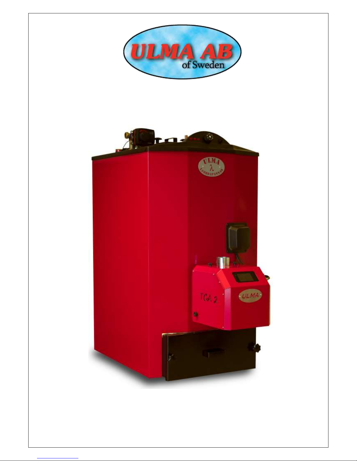
INSTALLATION AND MAINTENANCE OF
THE ULMA LAMBDA BOILER 20KW
Page 2
2
Chapter
Table of content
Page
1.
Information
3
2.
Function & description
4
3.
Measuring description – Technical data
6
4.
Building services installations schedule
7
5.
Wiring diagram
8
6.
Installation
9
7.
Boiler room and chimney
10
8.
Management and maintenance
11
9.
Data about pellet firing
12
10.
Declaration of conformity
13
12.
Test record
14
ULMA AB Energigatan 11 SE-512 53 Svenljunga, Sweden Phone +46 (0)325-17680
E-mail: [email protected]
www.ulma.se
ULMA AB reserves the right to changes in details and specifications without a preceding message.
Page 3

3
Information
• Keep this manual so that it is accessible to professionals and future needs.
• Read this manual carefully before starting up the boiler.
• The efficiency of the boiler is calculated after the maximum amount pellets that can be fed and
combusted in the burner during 1 hour (intended for combustion of normal wood pellets as an
average of the fuel specification).
• Follow the manual and its instructions carefully do recommended management and maintenance.
Registration to the local building authority in your municipality
N.B.: At every change of heating system, the local building authority of the municipality has to be
contacted and a so called “Construction Registration” is made.
Inspection
Heating plants installed today shall be inspected and approved by authorized inspector like the local
certified chimney-sweeper. The local building authority in the municipality can inform you how this
could work.
Important at installation
• Make sure expansion and cold water connection are correctly mounted, if you are unsure you may
control this by looking down in the connection pipes. The long pipe reaching down towards the
bottom of the boiler is cold water and the short expansion connection. The pipe connections are
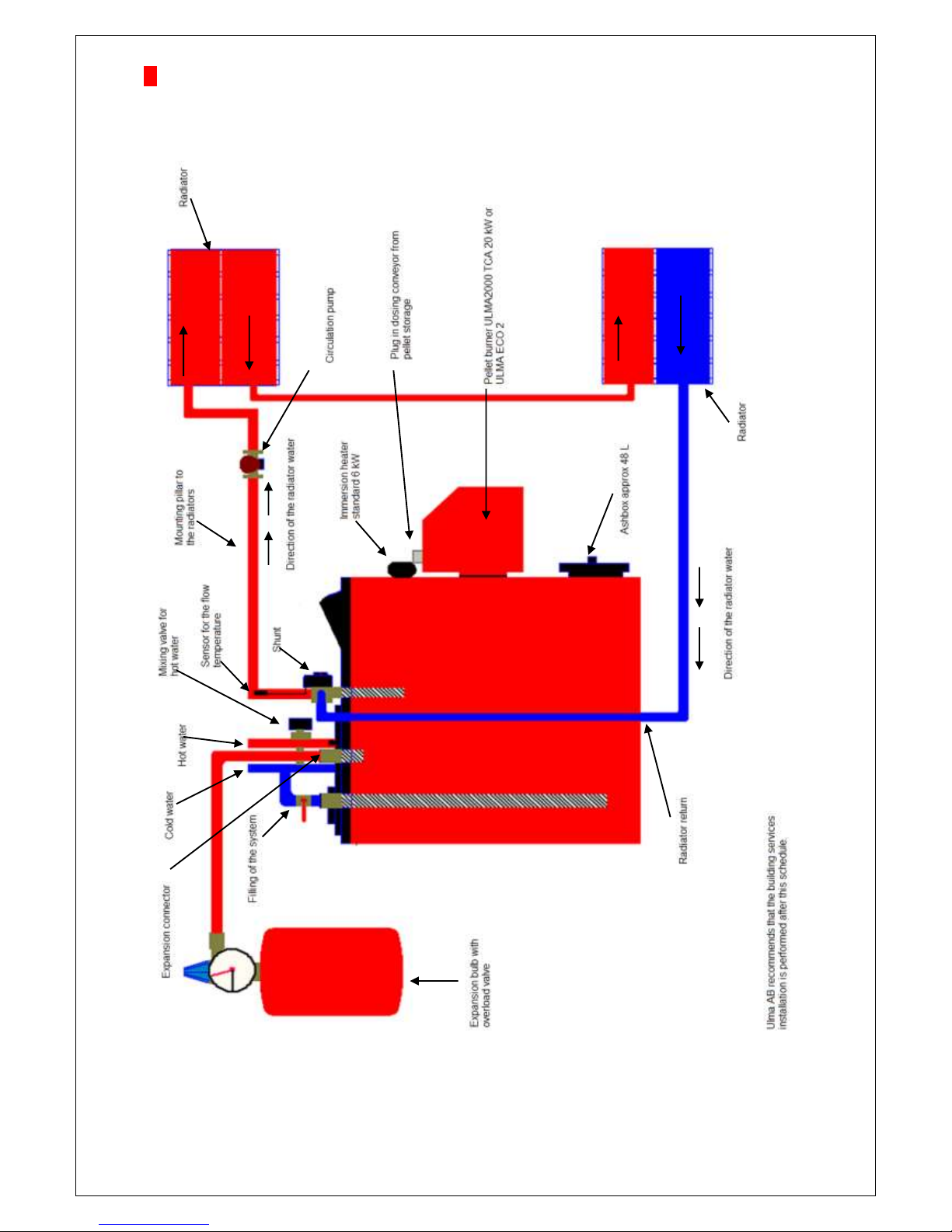
placed behind the connection of the shunt valve. (See connection schedule on page 5-6.)
• Make sure that boiler and heating system is water filled and de-aerated before starting the
combustion.
• Installation shall be made by certified ventilation and sanitation engineer and electrician.
• At operation with burner: Set the thermostat so that the immersion heater will be connected at
unintentional interruptions in operation of the burner.
•. N.B.! The burner shall be inserted to maximum in the boiler. Control this carefully in the future also
if the burner is disconnected for example cleaning and service.
• At adjustment of the burner draw limiter shall be adjusted after the draft condition of the chimney. .
• The boiler shall be connected electrically via an all-pole breaker with at least 3 mm length of break.
• The room giver should be on level zero when the boiler is put into operation, when the boiler then is
filled with water and reached maximum temperature the giver should be turned up to approx. 25
degrees so that a click is heard in the giver and then turned back to desired indoor temperature. By
doing this you activate (start) the circulation pump.
Sweeping
Chimney sweeping made in accordance with the fire-protection law shall be made frequently during
the year. This is made by your local chimney sweeper. Regular cleaning of heating surface of the
boiler shall be made in a way so that good operating economy is obtained. Prepare sweeping by
turning off the boiler at least a couple of hours before cleaning to minimize the amount of ignited ash.
Warning!
See to that the power to the boiler is turned off before the cap over the burner is removed and
dismount cabling to the burner when the burner is removed from the boiler.
Maintenance agreement increases operation length and life of the unit
ULMA AB recommends subscription of annual maintenance agreement.
For more information contact your local ULMA retailer.
Change of wear parts
ULMA AB always recommends that wear parts, when needed, are being changed by an authorized
service technician at your ULMA retailer. ULMA’s retailers can provide necessary spare parts and at
change make sure that the part being changed on the unit go through alignment and that a flue-gas
analysis of the unit is made.
Page 4
4
Function & description
ULMA LAMBDA BOILER
Belongs to a new generation of pellet boiler that is specially built only for pellet combustion which means
that it has a standing convection system and special design of the hearth to catch the smallest soot
particles on the convection surfaces and longest possible flue-gas way to increase the efficiency.
The boiler consists of a combustion chamber with a gas canal surrounded by an outer shell that holds
200 liter of water. At combustion of pellets the heat from the burner goes straight to the boiler water that
transports the heat to the hot water via a hot water coil which is 11 meters long. The boiler is mainly
meant for combustion of pellets but is also provided with a 6 kW immersion heater.
Sweeping
Regular cleaning of heating surfaces is made from the top by taking off the lid placed in the center on the
top of the boiler. The boiler is provided with an extra large ash box in the bottom part to facilitate the
maintenance. The ash box is emptied as required approx.. 1500 Kg pellet. Normally 3-4 times per year is
enough for an average house. Control of the ash amount in the box should be made at least one time per
month. The ash box holds about 48 L of ash.
Thermostat
Always set the thermostat at a lower temperature than the burner.
Shunting automaticity
The heat to the radiator system goes via a shunt valve. In the shunt valve the boiler water is blended with
the return water so that the right temperature is obtained in the radiator system in relation to the indoor
temperature.
Page 5
5
Small dimensions facilitate placing
The dimensions of the ULMA LAMBDA BOILER make it very easy to install. The small smooth
dimensions make it fit in boiler rooms that normally would be considered tight.
The pipe joints are located on the top of the boiler. The electrical installation is easily made via already
existing cables and you do not have to demount any parts for this procedure.
Service of the boiler is easy to make since all connections and components are easily accessible from
the front.
Page 6
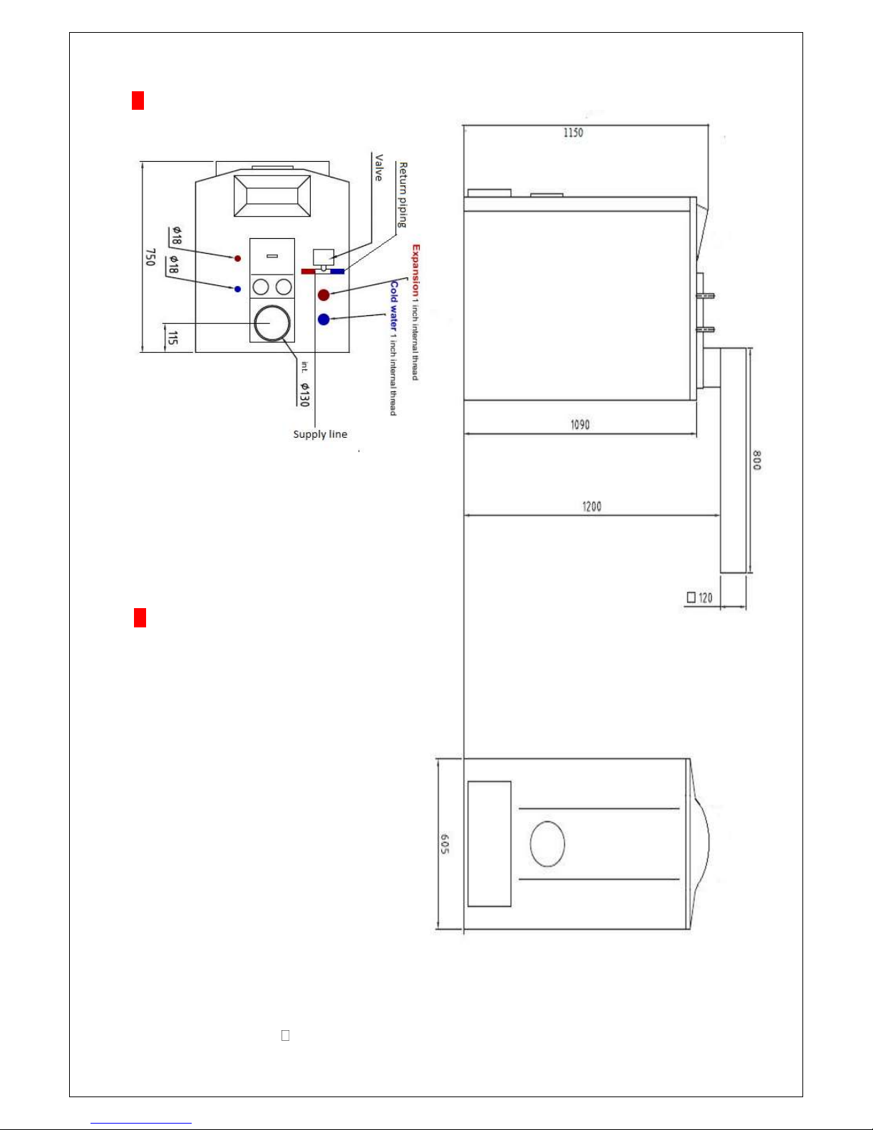
6
Dimension description
LpfA [dB] (ref. 20 μPa) 60 dBA
Max working pressure
1,5 bar
Flue pipe
120 x 120 mm
Water volume
200 L
My chimney area
80 cm2
Connection hole (burner)
Ø 154mm
Dept of hearth
350mm
Hight of hearth
350 mm
Power connection
400 VAC
Warranty
5 YEARS
My under pressure
1,5 / vp
Efficiency
Approx. 90- 92%
Max effect
20kW
Hot water coil
11m
Immersion heater
6kW
Ash box
Approx. 48 liters
Weight
Approx. 250 Kg
Technical data
Page 7
7
Building services installations schedule for ULMA LAMBDA 20kW pellet boiler
Page 8
8
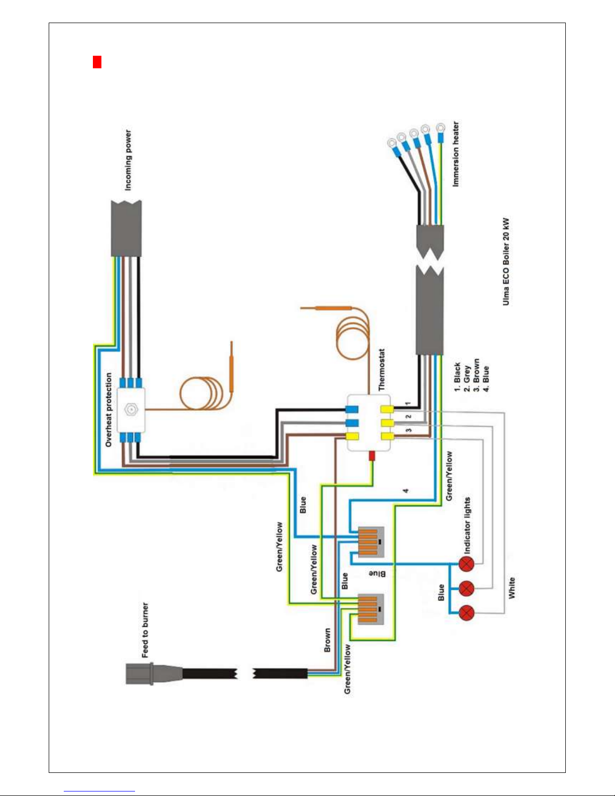
Wiring diagram
Page 9

9
Installation
Radiator system and expansion tank
Filling of the system shall be realized with all valves in open position and the circulation pump shall be
turned off. The system is carefully ventilated during the filling. When the unit has been running for a
couple of days ventilation and repeated filling should be made.
Note! See special instructions for filling of water.
The volume of the expansion tank is chosen in following way:
Open system: 5 % of the water volume in the heating system.
Closed system: The volume of the tank should be made from directions from manufacturer of closed
tanks.
In the table below examples of suitable expansion tanks for closed systems are shown.
Open system with 300 litres water volume requires at least 15 litres expansion tank.
* System volume = boiler volume + pipe volume + radiator volume
System volume (liter)*
Opening pressure (bar)
Oppression (bar)
Tank volume (liter)
70˚C - 90˚C
Approx. 300
1,5
0,5
18
Approx. 300
1,5
1,0
35
Firing with pellets and electricity at the same time
You can fire with both pellets and electricity at the same time. At dimensioning of the expansion pipe
or safety valve this must be considered.
Dimensions according to BFS 1988:18, 3:416.
Planning- and installation work
The planning – and installation work of the unit shall be made in a professional way with special
attention of common and local regulations and ordinances. .
The operation pressure is maximum 1,5 bar. Before the unit is put into work, and always at the
beginning of the combustion season following inspections should be made:
1. that the heating system is filled with water and ventilated
2. that the circulation pump is working
3. that the valves of the system are open
4. that potential control – and safety automatic system is working
5. that the chimney has required draft and that the fresh air ventilation is open
Safety valve
If a closed expansion tank is installed to the radiator system, the safety valve should be controlled 3-4
times per year. Activate the valve by pressing or turning the control and then make sure that water is
entering into the waste pipe that goes from valve to drainage.
Maximal hot water capacity
If you have a higher setting of the boiler temperature, the better hot water capacity you get
(recommended setting = 85˚C).
Filling of water
Before connecting of heat, the heating system has to be filled with water.
The filling of the systems is made in following way:
1. Open all stop taps, even the shunt valve. The pump shall be turned off.
2 Filling of water to boiler and radiator. Deareation is made on the radiators.
3 Delivery of cold water to the hot water coil. This is done by opening the stop tap on the cold water
fittings and ventilation is made by tapping out from a hot water tap.
4 When the system is completely filled the circulation pump can be started and heating begin.
5 When the water inside the boiler has reached set operating temperature, the pump should be turned
off and another airing be made on the radiators. This should be repeated several times. Keep in mind
that there is a lot of air inside the tap water. The volume can go up to approx. 8-10% why deaeration
can take time – especially at bigger volumes. Closed systems shall be filled so that the manometer
stands at the desired system pressure, distance from the manometer to the highest located radiator
in meter x 0,1 which gives the system pressure in bar. Set the red pointers of the manometer at the
same value as the big pointer. Preferred hot water temperature is set on the mixing fittings.
Page 10
10
Boiler room & chimney
The construction regulations of the National Housing Board include detailed norms for the design of
the boiler room, position of boilers in boiler rooms, performance of gas flue etc. The boiler room has to
have a supply air valve with an at least 2 dm² area, this may not be closed during the time when the
boiler is operating. Exhaust fan may not be installed inside the boiler room.
The installer and chimney-sweeper could give closer information.
The boiler should be placed on a flat and stably molded concrete bed.
The chimney connection
The ULMA LAMBDA BOILER has a design of the combustion chamber and flues that give the
possibility of firing with very high efficiency. The boiler is suitably connected to chimney/gas flue with
the provided turning flue pipe horizontally. The flue pipe canal may never go down. The chimney
should be inspected and possibly test pressed before installation if is has never been used and had
continuous maintenance by the local chimney-sweeper. At the slightest doubt, contact your certified
chimney-sweeper for inspection. Note that at too low flue gas temperature the flue gases can
condense with a risk of frost damage on the chimney as result. As a rule you should aim at least 7080°C flue gas temperature 1 m down in the chimney when the burner is running, this is primarily valid
for brick chimneys or similar material. The choice of flue gas temperature depends on the design and
isolation of the chimney, a steel chimney or bricked chimney with flue lining tube will not be as easily
damaged of low flue gas temperatures, provided that possibly condensate is continuously drained
from the lowest point of the chimney. This is the responsibility of the installer to control at installation.
Place the boiler at least 100 mm from the wall/bricks to facilitate service. Also leave room for possibly
existing cleanout door in the brick wall.
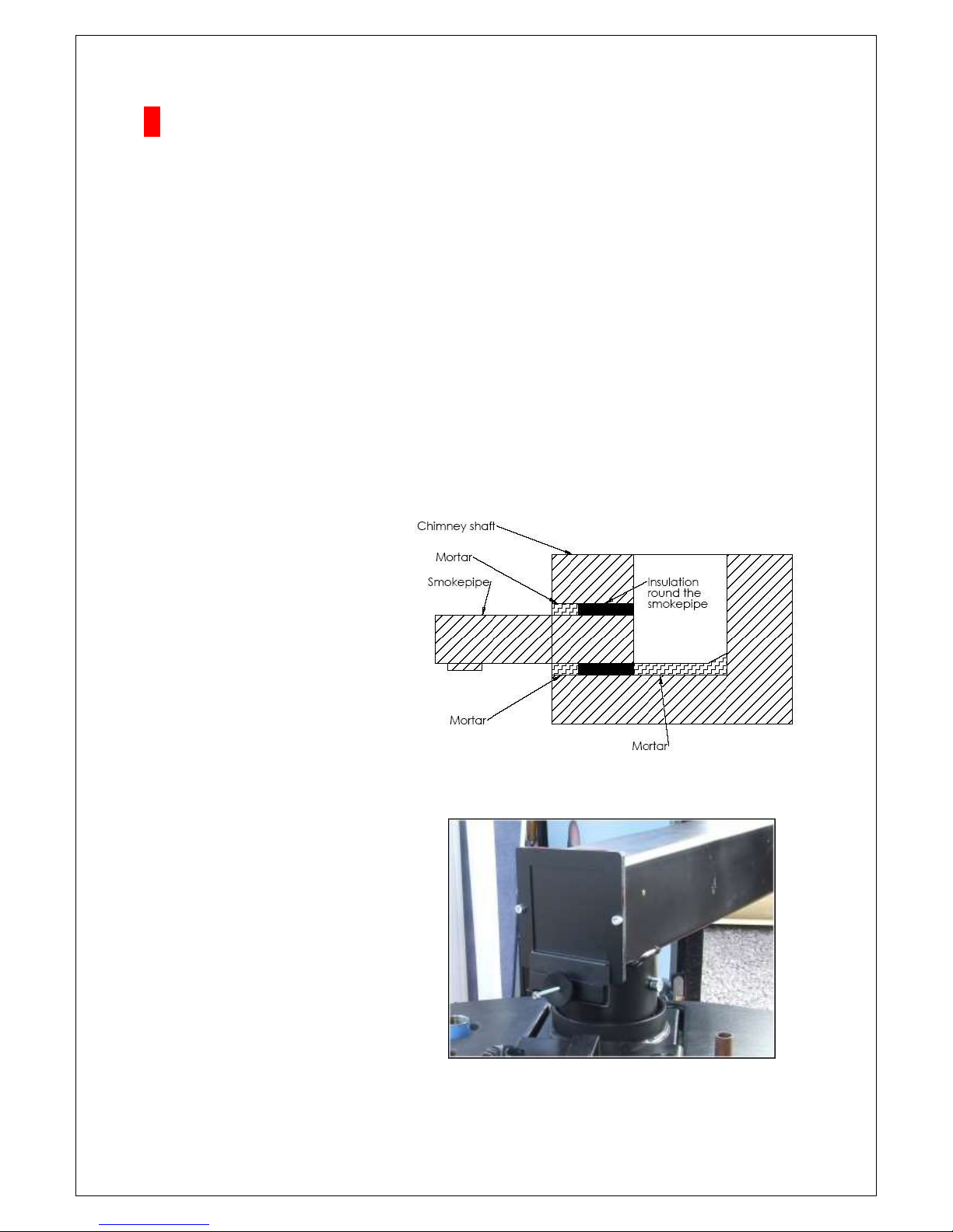
If the chimney is made out of bricks, you
have to take up the hole in the chimney
shaft so that there is an approx. 20 mm
blank space around the pipe. Then place
the pipe in the chimney shaft and mark out
the dept. Cut the pipe if needed. The pipe
should be placed so that it does not cover
the hole of the flue from above in any way.
Then wrap the pipe with a according to our
recommendations with 2-3 layers of heat
resistant insulating mat. Thickness of the
insulating mat is as normal standard
approx. 12 mm. Then add some extra
isolation from the outside in the opening
and then clean the wall brickworks.
Water the polish with a sprinkler a couple of
hours after to avoid cracking if the polish
burns too fast. The insulating mat makes it
closely and at the same time you escape
cracking in the chimney wall since the pipe
can move a little from thermal expansion.
The draft limiter ( Back draft door)
The draft limiter shall at installation be
adjusted by the installer of approx.
0.15 hPa under pressure. Too low under
pressure can create problems with
overheating of the burner and risk for
accumulation of flue gases in the hearth
that leads to producer gas puffs at the
ignition moment of the burner, a too high
under pressure can cause ignition problem.
Page 11
11
Management & Maintenance
The Immersion heater.
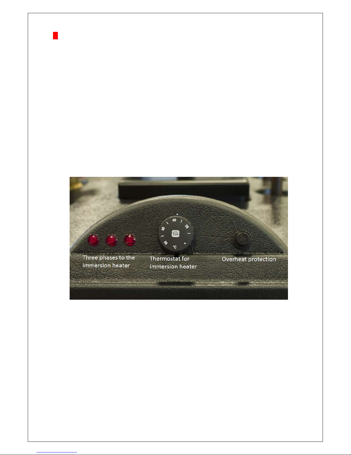
In the ULMA LAMBDA BOILER there is a preconnected three-phase immersion heater of 6 kW.
When the immersion heater is used as back up, you set the thermostat of the immersion heater
so that it is not connected without a reason, it shall only be used when there is something wrong with the
burner or as support-run at very high energy needs in the house. Operating indication lights are shining
when the immersion heater is running.
Cleaning of the boiler
In the ULMA LAMBDA BOILER the maintenance
has been minimized i.a. by a well planned
construction and the large ash box holds approx.
48 liters. Ash emptying is made as required.
Cleaning of the tubes of the boiler is realized when
the flue gas temperature has increased approx. 50
degrees compared to a new swept boiler. More
frequent intervals give increased efficiency. The
giver should be cleaned at least once per month.
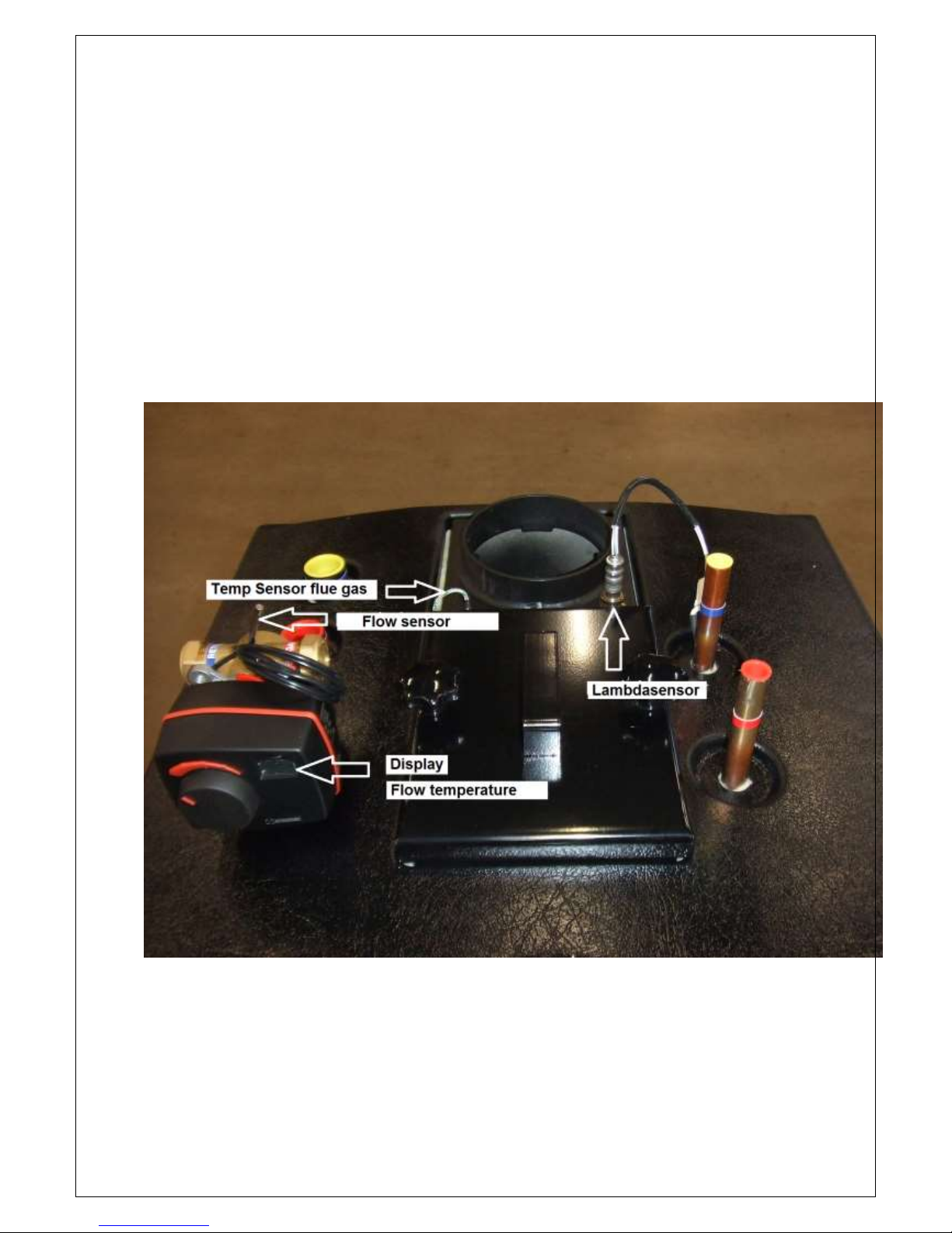
Giver for the flue gas temperature
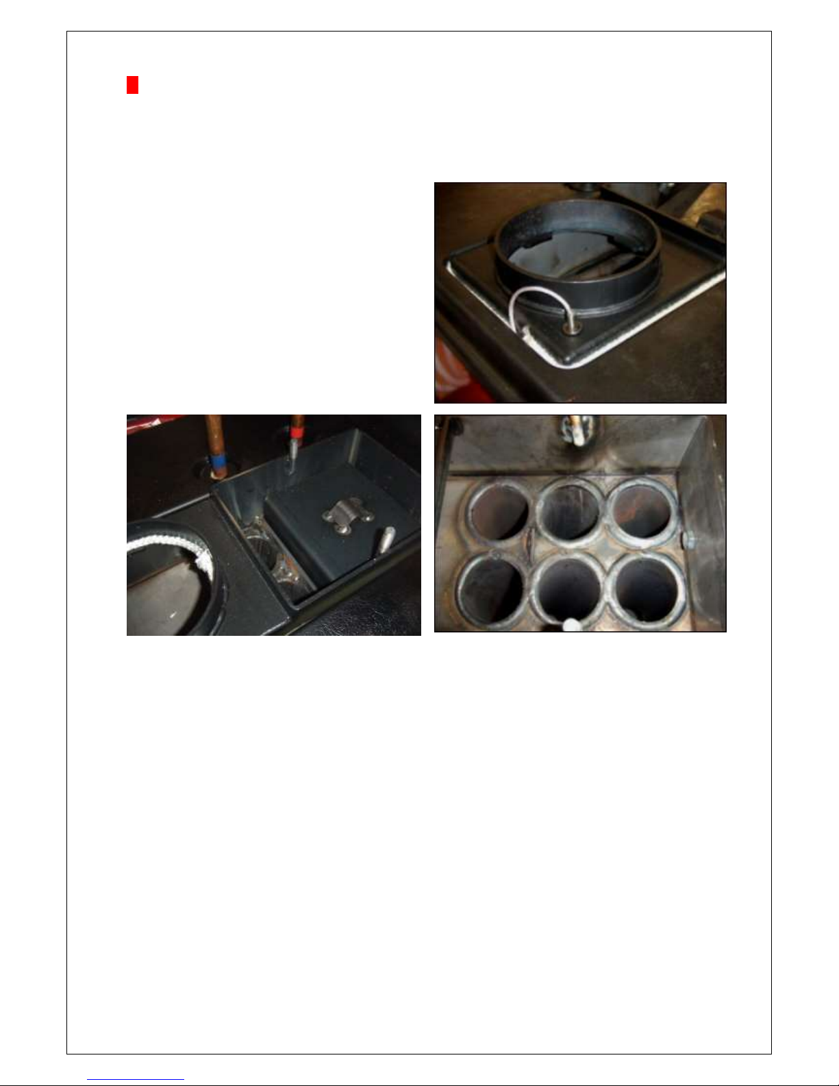
Under the door on the top of the boiler, you can reach the tubes
at the regular cleaning of the heating surfaces
The tubes shown on this picture without the flue gas break that
you can see on the picture to the left.
O.B.S! Very important to put where flue gas in a proper manner after completion of sweeping.
See picture above.
Be extra attentive of to the quality of the pellets at new delivery or change of deliverer.
At new delivery a flue gas analysis should be made. Therefore we recommend a service agreement.
Contact your local installer regarding information of agreement.
The tubes of the boiler should be cleaned 4-5 times per year (may vary some depending on consumption
and pellet quality) or when the flue gas temperature has risen with approx. 50 degrees since previous
cleaning.
• Turn off the burner a couple of hours before service.
• Lift up the soot door on the top and clean the tubes. (Use the enclosed tube wisp.)
Check the colour of ashes in the tubes and inside the lid. Should be gray to light brown. Is the colour
black, the burner must be adjusted, otherwise it shorten the life of the burner. See dealer for adjustment
of the burner.
• Pull out the burner and clean from ash residues between the burner pipes at least two times per year.
NOTE!
Always be careful with ash since it might be ignited. The ash should be kept in fireproof vessels.
Page 12
12
Data about pellet firing
At installation the unit shall always be adjusted with a flue gas instrument and not only with help of
the human eye. When the installation is in place and has been gotten into shape with a flue gas
instrument, ask for a print of the check measurement from the installer. There you should be able to
read the values like CO, O2, CO2, combustion efficiency, draft, flue gas temperature etc.
Goal values:
CO2 : 11%
CO :10 - 300 ppm
O2 : 8-10 %
hPa : -0,10 / -0,15
General facts about fuel pellets
A fuel pellet is per definition a”short cylindrical item” for combustion. Fuel pellets are made by
pressing of finely powdered dry fuel that is made by waste products from the forest industry. The
diameter of the fuel pellets existing on the Swedish market today, vary between 6-8 mm. The effect
on the outer environment is minimal at combustion of pellets. At the combustion in a pellet system of
for example a pellet boiler or stove the stored sun energy in the raw material is released. The
emissions of unburned hydrocarbons as well as dust are in almost all cases far below the marginal
values of the authorities. The carbon dioxide taken up and captured during the growth of the trees is
released in the process to once again be taken up by the nature. In other words a circuitry.
Combustion of pellets does not provide the atmosphere extra carbon dioxide which happens at
combustion of the fossil fuels oil, gas and coal.
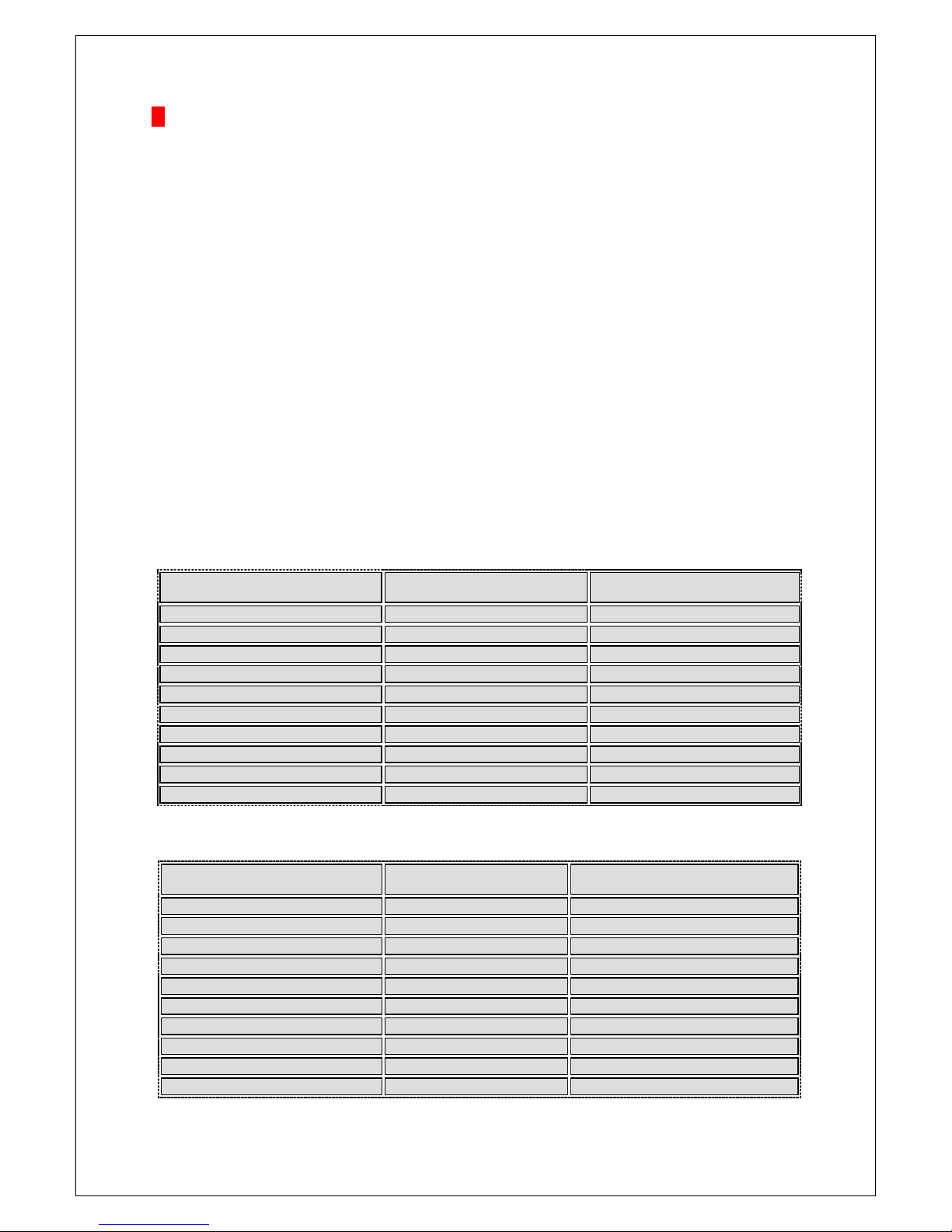
Comparison tables between Svanen market Norsk Pellets and Swedish standard SS 18 71 20
Norsk Pellets
*AnalyCen BE000720-05
Quality (in the storage of the
manufacturer)
Unit
Group1 (House pellets)
- Diameter – Length
mm
Max 5x Ø
- Bulk density
kg/m3
≥ 739
- Strength
Fines content in weight % < 3,15 mm
≤ 1,1
- Effective heat value
kWh/kg
≥ 4,88
- Ash content
Weight % of TS >
≤ 0,3
- Total Moisture content
Weight %
≤ 7,4
- Total Sulphur content
Weight of TS
≤ 0,01
- Content of additives
Weight % of TS
None
- Chlorides
Weight % of TS >
<0,01
- Ash melt process
C°
>1550
Swedish standard SS 18 71 20
Quality (in the storage of the
manufacturer)
Unit
Group1 (House pellets)
- Diameter – Length
mm
Max 4x Ø
- Bulk density
kg/m3
≥ 600
- Strength
Fines content in weight % < 3 mm
≤ 0,8
- Effective heat value
kWh/kg
≥ 4,7
- Ash content
Weight % of TS >
≤ 0,7
- Total Moisture content
Weight %
≤ 10
- Total Sulphur content
Weight % of TS
≤ 0,08
- ontent of additives
Weight % of TS
Content and kind shall be given
- Chlorides
Weight % of TS >
≤ 0,03
- Ash melt process
C°
Initial temperature (IT) is given
Page 13
13
Page 14
14
Test record
Date: ___________________________
Model: __________________________
Serial number: ____________________
Checkpoints
1. Connection and tension setting
2. Functional inspection indicator lights
3. Functional inspection thermostat
4. Functional inspection power to burner
5. Functional inspection immersion heater: Grey_____Ω Brown_____Ω Black_____Ω
5. Serial no
6. Control of content in packaging
Fiberglass cord
Sweeping brush
Manual
Clutch kit-mixing valve, relief valve
Checked and approved by: ______________________________
Name: ______________________________
8. Control of accessories supplied.
Smoke pipe
Draft limiter
Checked and approved by: ______________________________
Name: ______________________________
 Loading...