

Page 1
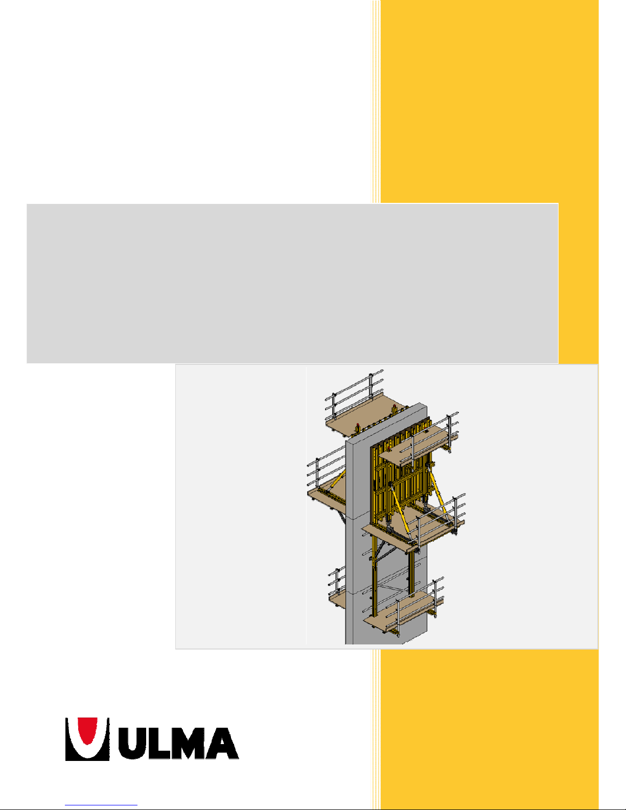
User Guide
BMK
Climbing brackets
02FIR12
Page 2
DISCLAIMER:
Any safety provisions as directed by the appropriate
governing agencies must be observed when using our
products.
The pictures in this brochure are snapshots of situations at
different stages of assembly, and therefore are not complete
images. For the purpose of safety, they shall not be deemed
as definite.
All instructions regarding safety and operation contained in
this brochure, and the data on stress and loads must be
respected. ULMA Construcción’s Technical Department must
be consulted any time that field changes alter our equipment
installation drawings.
The loads featured in this document, related to the basic
parts of the product, are approximate.
Our equipment is designed to work with accessories and
items produced by our company only. Combining such
equipment with other brands is not only dangerous without
having made all corresponding verifications, it also voids any
and all our warranties.
The company reserves the right to introduce any
modifications deemed necessary for the technical
develo
p
ment of the product.
"Original document" produced and approved by ULMA Construcción.
All rights reserved.
Neither the whole nor any part of this document may be reproduced or transmitted in any form or by any means (electronic or
mechanical), including photocopy, recording or any form of information storage or retrieval system without the written permission of
ULMA Construcción.
Copyright by ULMA C y E, S. Coop
Information sign
Safety sign
Warning sign
Control sign
Page 3

3
TABLE OF CONTENT
1. PRODUCT DESCRIPTION .................................................................................................................... 4
1.1. CLIMBING BRACKET BMK-240 ..................................................................................................................... 6
1.2. CLIMBING BRACKET BMK-170 ..................................................................................................................... 7
2. SYSTEM COMPONENTS AND ACCESSORIES ........................................................................................ 8
2.1. GRAPHIC DESCRIPTION ............................................................................................................................... 8
2.2. ITEMS DESCRIPTION ................................................................................................................................. 13
3. ASSEMBLY, USE AND DISMANTLING ................................................................................................ 31
3.1. INSTRUCTIONS FOR THE CLIMBING BRACKET BMK SYSTEM: FIRST POURING STAGE ON THE GROUND .................................... 31
3.2. INSTRUCTIONS FOR THE CLIMBING BRACKET BMK SYSTEM: SECOND POURING STAGE - FIRST CLIMBING STAGE ....................... 33
3.3. INSTRUCTIONS FOR THE CLIMBING BRACKET BMK SYSTEM FOR THE CONSTRUCTION OF HOLLOW PIERS ................................. 37
3.4. PLATFORMS ASSEMBLY ............................................................................................................................ 43
3.5. LIFTING HOOK MK .................................................................................................................................... 45
3.6. FORMWORK PANEL CONNECTION TO CLIMBING STRUCTURE .................................................................... 47
3.7. STRIPPING SYSTEM ................................................................................................................................... 50
3.8. HEIGHT ADJUSTMENT ............................................................................................................................... 53
4. SOLUTIONS .................................................................................................................................... 55
4.1. STRAIGHT WALLS ...................................................................................................................................... 55
4.2. INCLINED WALLS ...................................................................................................................................... 60
4.3. CURVED AND POLYGONAL WALLS ............................................................................................................ 63
4.4. ANCHORAGE SOLUTIONS ......................................................................................................................... 63
5. SYSTEM PROPERTIES ....................................................................................................................... 68
5.1. MAXIMUM SIZE OF FORMWORK PANEL .................................................................................................... 68
5.2. LIMITS OF ANCHORAGES .......................................................................................................................... 69
6. TERMS AND CONDITIONS OF USE .................................................................................................... 70
6.1. LOAD CASES ............................................................................................................................................. 70
6.2. MAXIMUM WORKING LOADS ................................................................................................................... 70
6.3. ANCHORAGE STRENGTH ........................................................................................................................... 71
6.4. SAFE HANDLING GUIDELINES ................................................................................................................... 71
7. LEGAL REFERENCES ......................................................................................................................... 74
7.1. LEGAL REFERENCES .................................................................................................................................. 74
8. APPENDICES ................................................................................................................................... 75
8.1. DECLARATION OF CONFORMITY: LIFTING HOOK MK ................................................................................. 75
Page 4
4
BMK CLIMBING BRACKETS
1. PRODUCT DESCRIPTION
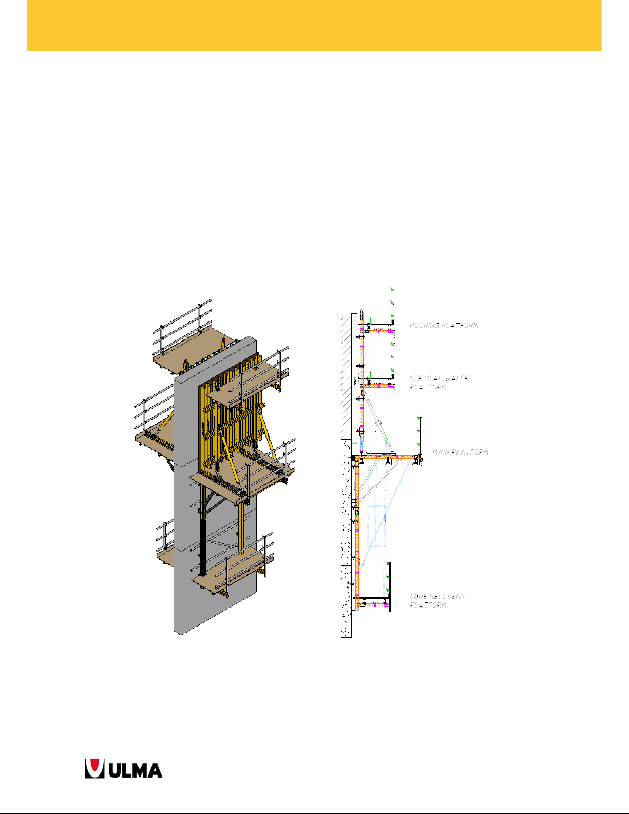
The Climbing Bracket BMK system is mainly used for the construction of double-sided walls and piers. It is
supported on anchor cones embedded in the concrete wall from a previous pouring stage.
The system allows of two different stripping options:
With rack and pinion system: The formwork is supported on a carriage which enables to move it
back up to 80 cm from the wall. This system eases the cleaning and placing of steel reinforcement.
With tilt-back system: The formwork can be separated some 5 cm from the wall for stripping and
moreover it can be tilted.
The formwork together with the climbing structure is moved up to the next pouring stage with crane.
Apart from all other necessary components for the formwork, the working platforms can be highlighted as
constituting factors for product safety.
Page 5
5
BMK CLIMBING BRACKETS
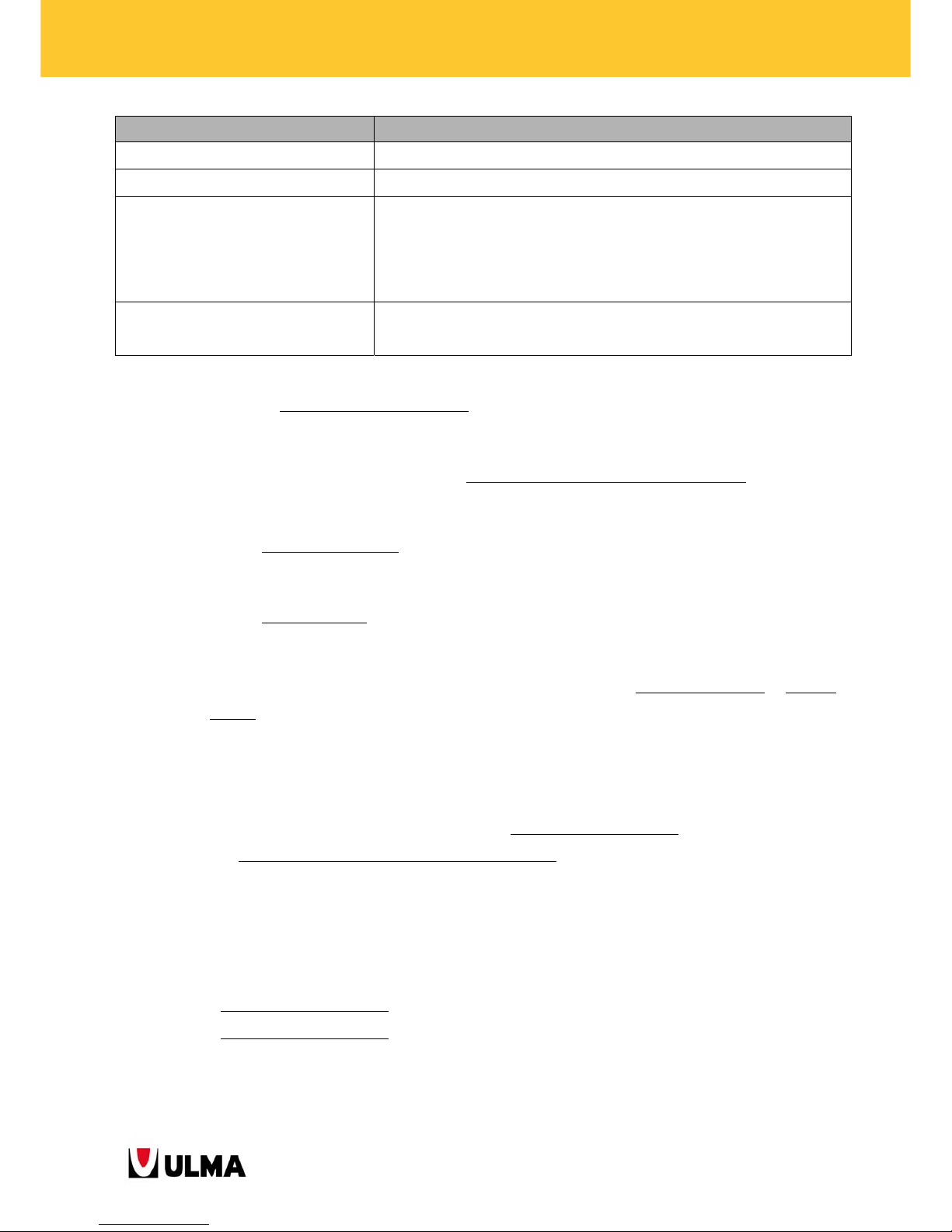
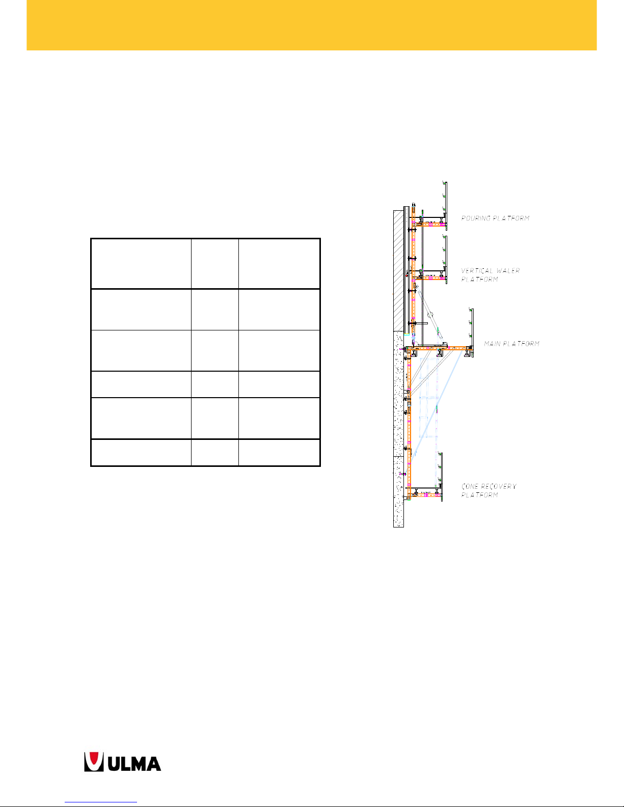
PLATFORM TYPES FUNCTION
CONCRETE POURING PLATFORM It is used for concrete pouring and for the hooking of the crane.
VERTICAL WALER PLATFORM It is used to place and release the tie rods.
MAIN PLATFORM
This is the amplest working platform. It is used as working area for the
stripping, approaching and plumbing of the formwork panel as well as for
the placing of the steel reinforcement, tie rods and for the cleaning of the
panel.
CONE RECOVERY PLATFORM
It is used to recover the cones left in the concrete from previous pouring
stages and for the placing of the wind sling fixers.
The main features of the Climbing Bracket BMK system are:
Use with different formwork products
: Mainly with ORMA modular formwork, beam-based
formwork (ENKOFORM V-100 and ENKOFORM VMK) and metal formwork.
The climbing brackets/frames consist of standard walers MK with accessories bolted
to them. This
entails the following advantages:
o Very versatile system
: It offers the versatility of the MK system and enables different
configurations by making use of some MK accessories.
o Transport saving
: The brackets/frames can be delivered disassembled to the building site
which contributes to the reduction of transport cost.
The climbing brackets are already equipped with a stripping system, with rack and pinion
or tilt-back
system.
The formwork panels are adjusted of height with levelling jacks, and push-pull props to enable their
plumbing.
Capability to adapt to complex wall geometries (inclined walls, curved walls
etc.)
The working platforms provide a high level of safety
due to their ample space to carry out all
required construction works.
Possibility to use two anchor types: DW15/M24 or DW20/M30.
The basic range of Climbing Brackets BMK is as follows:
Climbing Bracket BMK-240
Climbing Bracket BMK-170
Page 6
6
BMK CLIMBING BRACKETS
1.1. CLIMBING BRACKET BMK-240
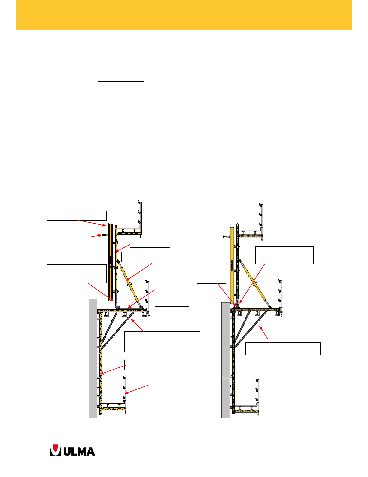
This bracket system offers 2 configurations or rather different assembly types: the mobile configuration with roll-
back carriage and the fixed configuration
with tilt-back system.
Mobile configuration with Roll-Back Carriage: The formwork is joined to the main platform through the
Roll-Back Carriage (1991444) which is operated by a rack and pinion mechanism to separate the panels
from the wall at stripping. A push-pull prop serves to plumb the formwork and the height adjustment of
the panels is enabled by the Waler Screw TR53X6 (0302020) which connects the vertical waler to the Rollback carriage.
Fixed configuration with Tilt-Back System:
The formwork is joined to the main platform through the TiltBack MK-120 (1991467). The panels can be separated from the poured concrete wall by a distance of
about 5 cm. The Connector MK Screw Waler Base (1991517) enables the panel height adjustment by
connecting the vertical waler to the stripping mechanism.
Mobile configuration
Fixed configuration
Climbing Bracket BMK-240
(1991424)
Tilt-Back
BMK-240 Frame (1991425)
Push-Pull Prop
Roll-Back
Carriage
Formwork panel
Anchorage
Vertical Waler
Waler Screw TR53X6
Connector MK Screw
Waler Base
Waler M
K
Page 7
7
BMK CLIMBING BRACKETS
1.2. CLIMBING BRACKET BMK-170
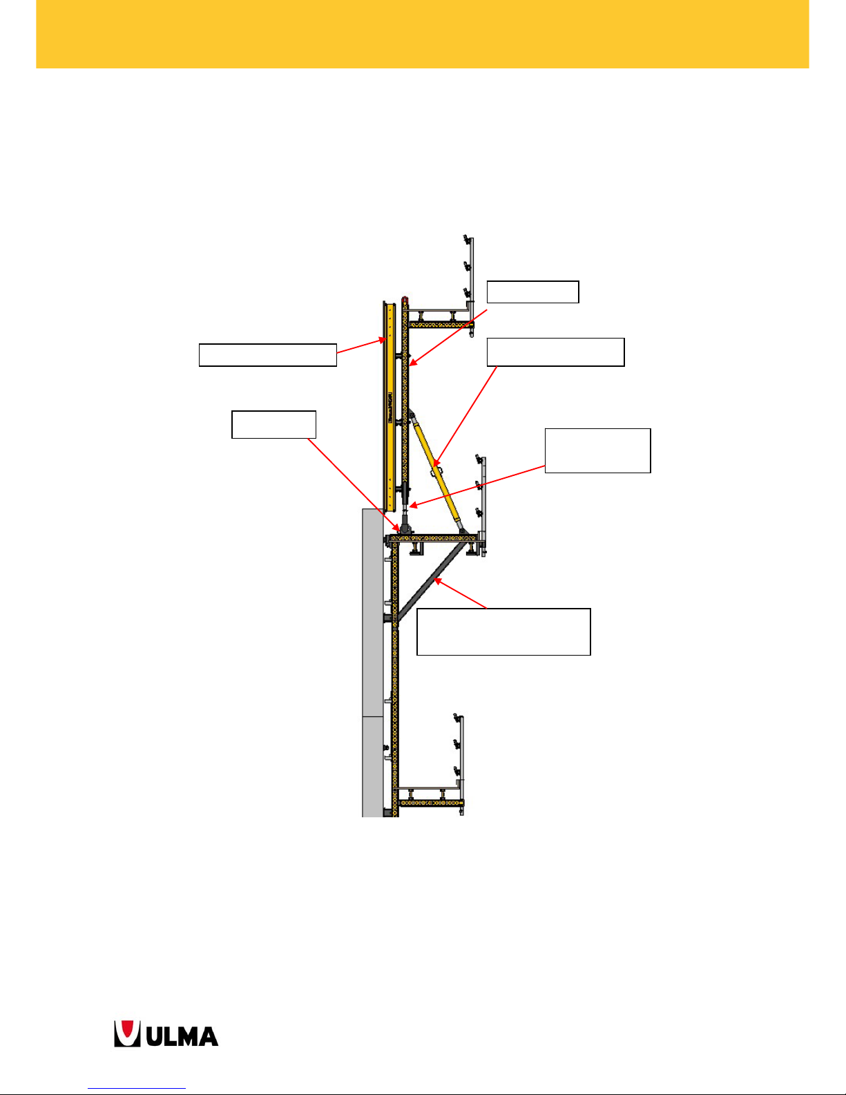
This climbing bracket only offers the fixed stripping configuration with which the formwork is detached from the
wall by about 5 cm with the Tilt-Back MK-120 (1991467). The Connector MK Screw Waler Base (1991517) enables
the panel height adjustment. The components are the same as for the fixed configuration of the climbing brackets
BMK-240 and BMK-220.
Climbing Bracket BMK-170
(1991417)
Push-Pull Prop
Connector MK
Screw Waler Base
Formwork panel
Vertical Waler
Tilt-Back Base
Page 8
8
BMK CLIMBING BRACKETS
2. SYSTEM COMPONENTS AND ACCESSORIES
2.1. GRAPHIC DESCRIPTION
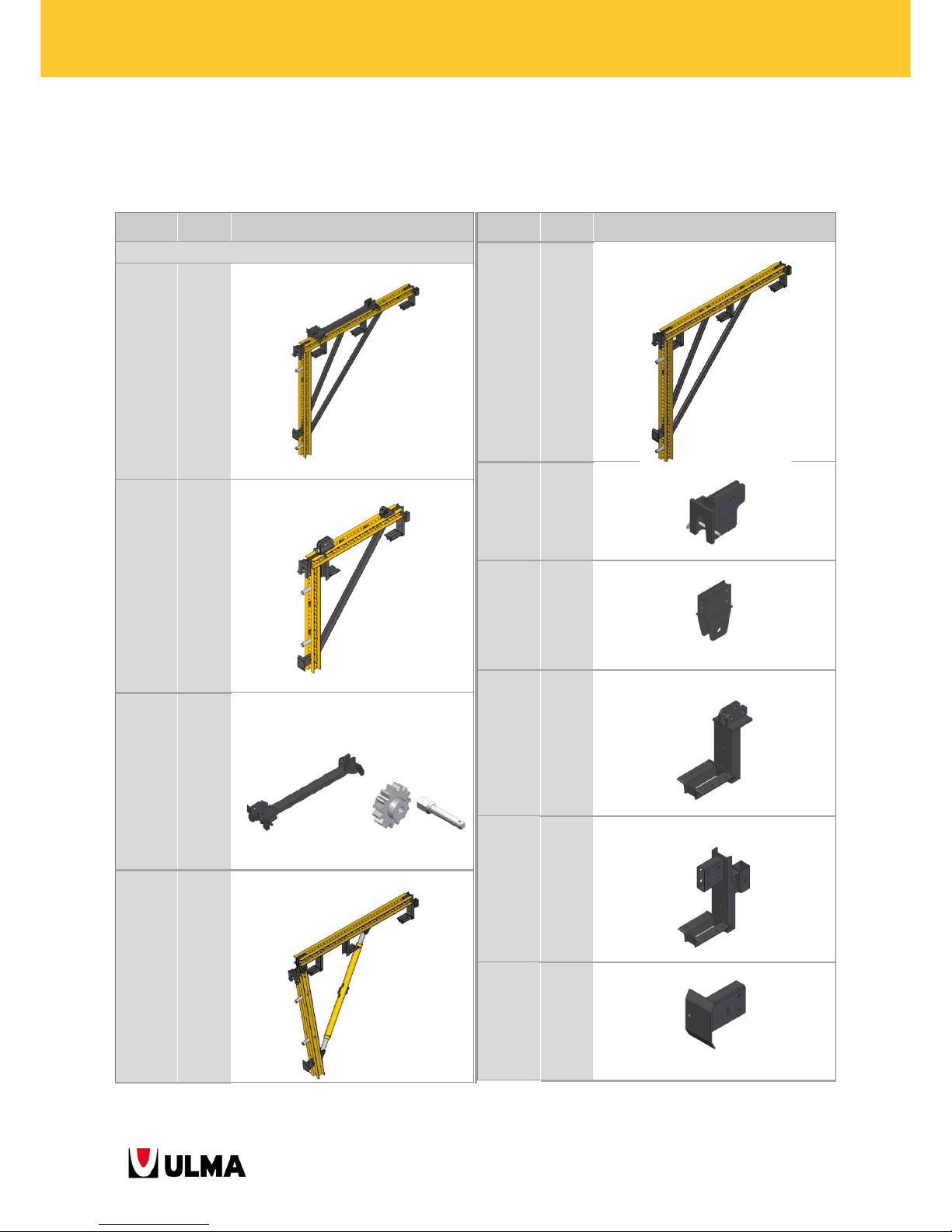
Item no.
Weight
(kg)
Item name
SUPPORT ON WALL COMPONENTS
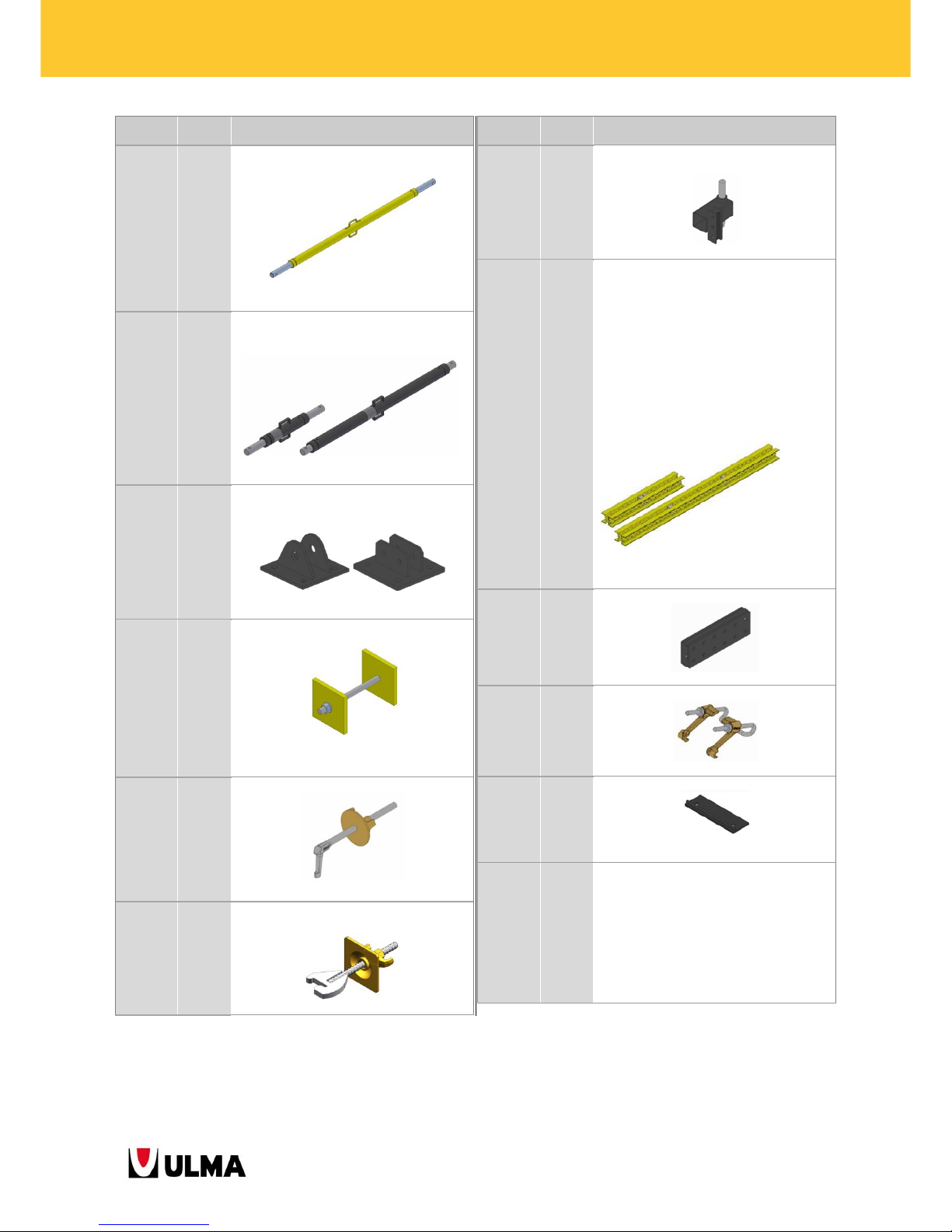
1991424 231 CLIMBING BRACKET BMK-240
1991417 163 CLIMBING BRACKET BMK-170
1991444
1991456
1991457
9071300
38.5
0.8
0.3
0.02
ROLL-BACK CARRIAGE MK-120
GEAR MK
GEAR SHAFT MK
SPRING PIN 5X30 DIN 1481
Painted black zinc-coated
1991465 225 HINGED BMK-240 FRAME
Item no.
Weight
(kg)
Item name
1991425 194 BMK-240 FRAME
1991410 14.4 FIXED HEAD
Painted black
1991503 6 MK HINGED HEAD
Painted black
1991427 7.7 PLATFORM SUPPORT MK-120
Painted black
1991434 9,3 PLATFORM BACK SUPPORT MK-120
Painted black
1991487 2.7 BOTTOM SUPPORT
Painted black
Page 9
9
BMK CLIMBING BRACKETS
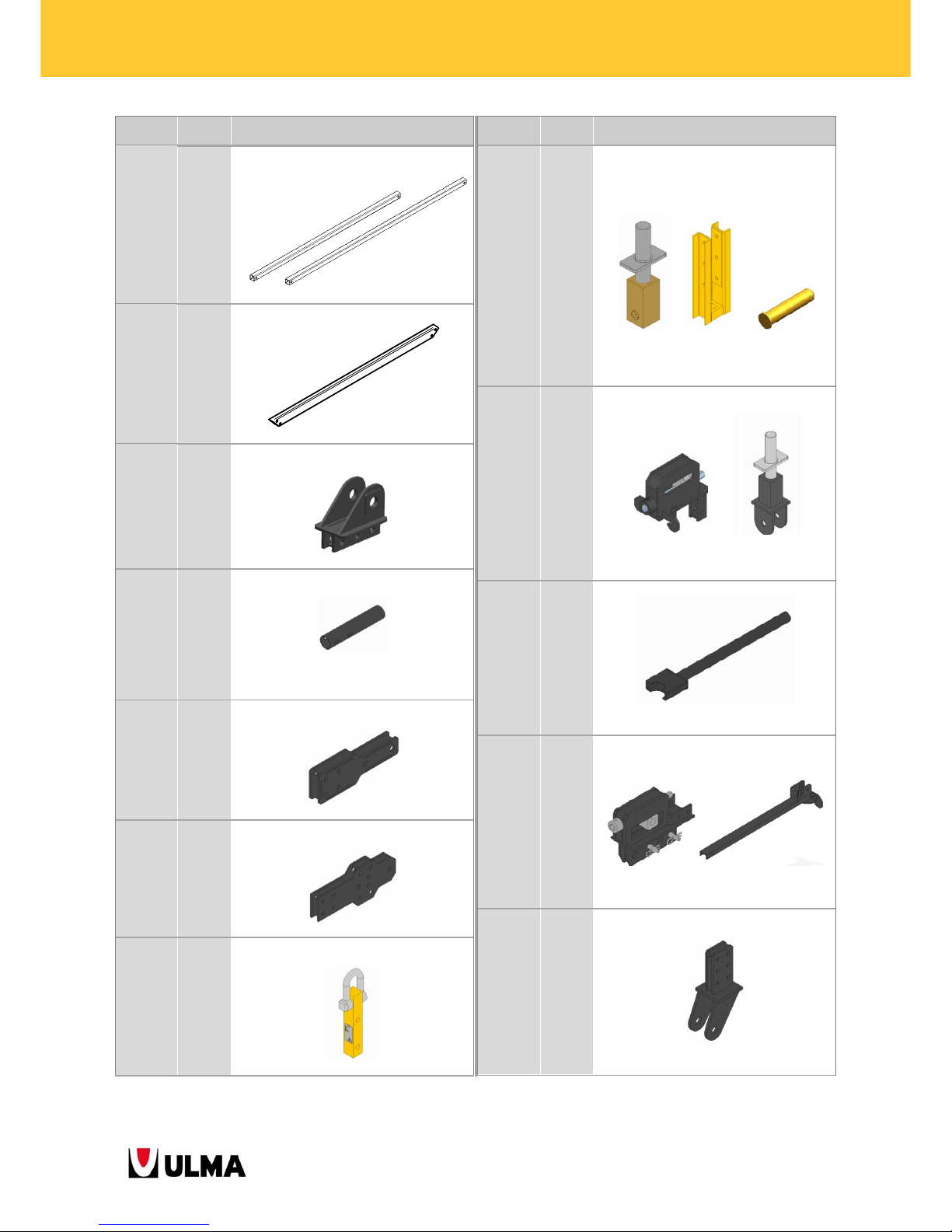
Item no.
Weight
(kg)
Item name
1991485
1991482
12.1
17.6
DIAGONAL MK 1.125X1.750/1797
DIAGONAL MK 2X2.125/2625
Painted black
1991498 21 DIAGONAL BMK-170
Painted black
1991439 4.5 PUSH-PULL PROP HEAD MK-120
Painted black
1990570 0.82 HANDRAIL HEAD MK
Painted black
1991458 5,1 AXIAL NODE M 2-D20 MK
Painted black
1991476 8.8 WALKWAY HINGED CONNECTOR
Painted black
1991360 7.1 LIFTING HOOK MK
Yellow-painted steel
Item no.
Weight
(kg)
Item name
0302020
1991570
0335153
0250000
10.8
13,5
0,40
0,03
WALER SCREW TR53X6
WALER MK-120 SCREW BRACKET
PIN W/HEAD D20X100
PIN COTTER R/5
Bichromate Painted Bichromate
treated yellow treated
(Zinc screw)
1991467
1991517
12
15.1
TILT-BACK MK-120
CONNECTOR MK SCREW WALER BASE
Painted black
Zinc-coated axes
0331013 2,6 HANDLE SCREW TR53
Painted black
1991463
1991450
24.6
25
INCLINED TILT-BACK MK-120
ASSSEMBLY RACK MK-120
Painted black, zinc-coated bolts and axes
1991593 12.8 MK-120 SINGLE SIDED CONNECTOR
Painted black
Page 10
10
BMK CLIMBING BRACKETS
Item no.
Weight
(kg)
Item name
0333014
1991514
46.5
41.7
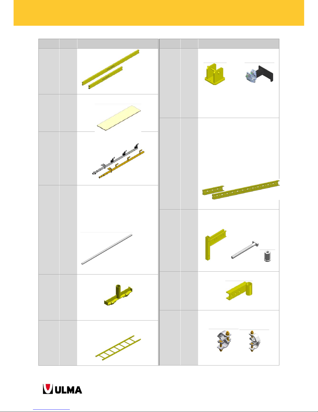
PUSH-PULL PROP TR63 2.04-2.72
PUSH-PULL PROP TR63 1.52-2.2
Painted yellow (Zinc-coated screw jack)
1960115
1960130
1960125
24.1
33.4
38.1
PUSH-PULL PROP E 1.51-2.2
PUSH-PULL PROP E 2.15-2.75
PUSH-PULL PROP E 2.7-3.3
Painted black (zinc-coated screw jack)
0333055
1960545 7 6.7
PUSH-PULL PROP SHOE TR63
PUSH-PULL PROP E SHOE 2 D20x48
Painted black
0260001 6.12 CLAMP M20X330 (2P-150X150)
Painted yellow (Zinc-coated screw jack)
1900448 1.41 WALER HOOK
Zinc-coated (Bichromate-treated nut)
0333004 2.3 WALER FIXING HOOK
Zinc-coated (Bichromate-treated nut)
Item no.
Weight
(kg)
Item name
19915675.8 ADJUSTMENT JACK MK-120
Painted Black (zinc-coated screw jack)
1990209
1990211
1990213
1990215
1990217
1990219
1990221
1990225
1990229
1990233
1990237
1990239
1990245
29.4
35,5
41.9
47,9
54.3
60.5
68.6
80.9
93.4
107.6
120.1
126.3
146.7
WALER MK-120 / 1.125
WALER MK-120 / 1.375
WALER MK-120 / 1.625
WALER MK-120 / 1.875
WALER MK-120 / 2.125
WALER MK-120 / 2.375
WALER MK-120 / 2.625
WALER MK-120 / 3.125
WALER MK-120 / 3.625
WALER MK-120 / 4.125
WALER MK-120 / 4.625
WALER MK-120 / 4.875
WALER MK-120 / 5.625
Profile painted yellow/ Space tube painted
black
1990395 6.5 ORTHOGONAL JOINT MK
Painted black
1960375 0.81 WALER-VM20 CLAMP 2T
Bichromate-treated and zinc-coated
0919259 1.7 PLATE CLAMP DU-DU
Painted black
1940191
1940172
1950129
1940144
1950130
1940146
1950112
1950113
1940149
7.25
9.12
12.25
14.5
16.5
18
19.5
24.5
29.5
BEAM VM 20/1.45
BEAM VM 20/1.9
BEAM VM 20/2.45
BEAM VM 20/2.9
BEAM VM 20/3.3
BEAM VM 20/3.6
BEAM VM 20/3.9
BEAM VM 20/4.9
BEAM VM 20/5.9
Page 11
11
BMK CLIMBING BRACKETS
Item no.
Weight
(kg)
Item name
Painted yellow
7251132
7251136
15
18.9
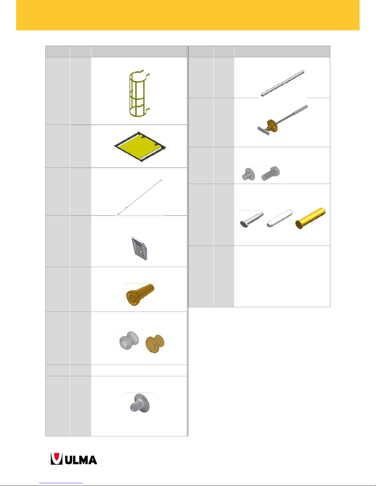
3 LAYER PLYWOOD 2000X503X27
3 LAYER PLYWOOD 2500X500X27
2211156
2211185
9.6
8
HANDRAIL POST 1.5
HANDRAIL POST 1.5 TBL
Zinc-coated Painted yellow
2125288
2125289
2125290
2125291
2125647
2125249
2125648
2125250
2125251
0200600
1.8
3.7
5.5
7
8.7
11.4
12.1
14.6
18
19.98
TUBE 48/0.5
TUBE 48/1.1
TUBE 48/1.6
TUBE 48/2.1
TUBE 48/2.6
TUBE 48/3.1
TUBE 48/3.6
TUBE 48/4.1
TUBE 48/5
TUBE 48/6
Galvanised (the 6 m one is painted)
0260505 3.4 SIMPLE BRACING
Painted yellow
0333008
0333009
14.1
19.4
LADDER C2.1
LADDER C3
Painted yellow
Item no.
Weight
(kg)
Item name
0333010
0333011
1.6
1.6
LADDER FIXER
LADDER HANGER
Painted Painted black
Yellow (zinc-coated
coupler)
1990109
1990111
1990113
1990115
1990117
1990119
1990121
1990125
1990129
1990133
1990137
13.7
16.9
20
23.1
26.2
29.3
32.4
38.6
44.8
51
57
PROFILE MK-120 / 1.125
PROFILE MK-120 / 1.375
PROFILE MK-120 / 1.625
PROFILE MK-120 / 1.875
PROFILE MK-120 / 2.125
PROFILE MK-120 / 2.375
PROFILE MK-120 / 2.625
PROFILE MK-120 / 3.125
PROFILE MK-120 / 3.625
PROFILE MK-120 / 4.125
PROFILE MK-120 / 4.625
Painted yellow
2211165
1861122
7238001
6.9
0.39
0.22
VM HANDRAIL SUPPORT LONG
PANEL BOLT
HEXAGONAL NUT 15
Painted yellow Zinc-coated
0121004 2.9 HANDRAIL SOCKET D50
Painted yellow
2125148
2125147
1.2
1.3
RIGHT ANGLE COUPLER 48/48
SWIVEL COUPLER 48/48
Galvanised (bichromate-treated screw jack)
Page 12
12
BMK CLIMBING BRACKETS
Item no.
Weight
(kg)
Item name
0333012 13,1 LADDER PROTECTION
Painted yellow
0333013 11.7 LADDER HATCH
Structure painted black + board
0333018 2.83 WIND SLING 12 (5T)
1901804
0333016
2
2.98
WIND SLING FIXER M24
WIND SLING FIXER M30
Painted black
1904080
0238050 1 2
CONE DW15/M24
CONE DW20/M30
Bichromate-treated
1901089
0238043
1.6
1.62
CLIMBING RING DW15-NT20
CLIMBING RING NT20
Zinc-coated (DW 15-NT20) / Bichromate
treated (NT 20)
9053013
0243013
0.54
0.92
BOLT M24X120 DIN-931-10.9
BOLT M30X130 DIN-931-10.9
0230005
0238025
0.56
0.97
FIXED ANCHOR DW15
FIXED ANCHOR DW20
Painted black
Item no.
Weight
(kg)
Item name
0230100
0234100
1.7
2.6
TIE ROD 15/1
TIE ROD 20/1
1901250 3 CONE-WALER TIE 90
Zinc-coated (bichromate-treated nut)
1900210
0238045
1900211
0.2
0.32
0.04
CONE POSITIONER M24
CONE POSITIONER M30
POSITIONER SPANNER
Zinc-coated
0252070
0253215
0253413
0250000
0.28
1.05
1.1
0.03
PIN E20x70
PIN D32X150
PIN W/HEAD D34X135
COTTER PIN R/5
Zinc-coated Zinc-coated
Bichromate-treated
0241690
0241670
0241645
0241614
0242080
0241600
0241601
0241608
0242008
9700225
9700226
0.16
0.14
0.10
0,24
0.26
0.03
0,01
0.04
0.06
3.9
0.2
BOLT M16X90 DIN 931-8.8
BOLT M16X70 DIN 933-8.8 C
BOLT M16X45 DIN 933-8.8 C
BOLT M16X140 DIN 931-8.8
BOLT M20x80 DIN 931-8.8
NUT M16 DIN 934 – 8
WASHER A16 DIN125
LOCKNUT M16 DIN985-8
LOCKNUT M20 DIN 985 – 8
TELESCOPIC RATCHET WRENCH 3/4
SOCKET 3/4 WIDTH ACROSS FLATS 24
Page 13
13
BMK CLIMBING BRACKETS
2.2. ITEMS DESCRIPTION
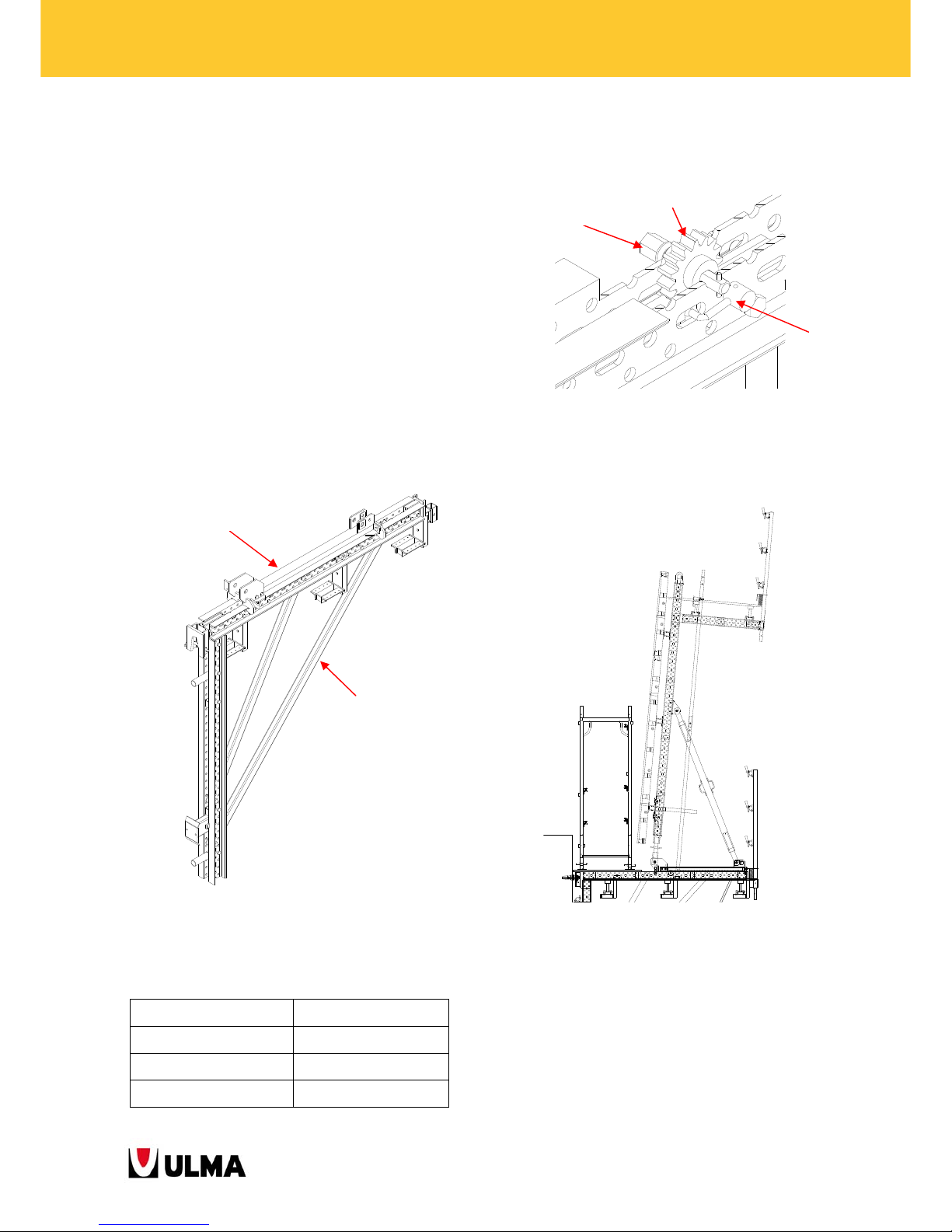
2.2.1. Climbing Bracket BMK-240 (1991424)
The shown climbing bracket is equipped with the
mobile stripping configuration, that is, with roll-back
carriage.
The means of transmission of all acting loads to the
concrete are the anchor cones.
The climbing bracket consists of:
BMK-240 Frame (1991425)
Roll-Back Carriage MK (1991444)
Gear MK (1991456), Gear Shaft MK (1991457)
Gear Locker MK (1991510), Cotter Pin R/4
(9023100)
The Roll-back carriage allows moving the formwork
back to different distances depending on the
formwork product:
As mentioned, the stripping system works with a rack
and pinion mechanism assembled to the centre part
of the horizontal beam of the climbing bracket.
The obtained stripping distance is sufficient to be
able to use BRIO or DORPA scaffolding to place the
steel reinforcement.
STRIPPING DISTANCE
ORMA 915mm
Enkoform V-100 815mm
Enkoform VMK 795mm
1991444
1991425
1991456
1991510
1991457
Page 14
14
BMK CLIMBING BRACKETS
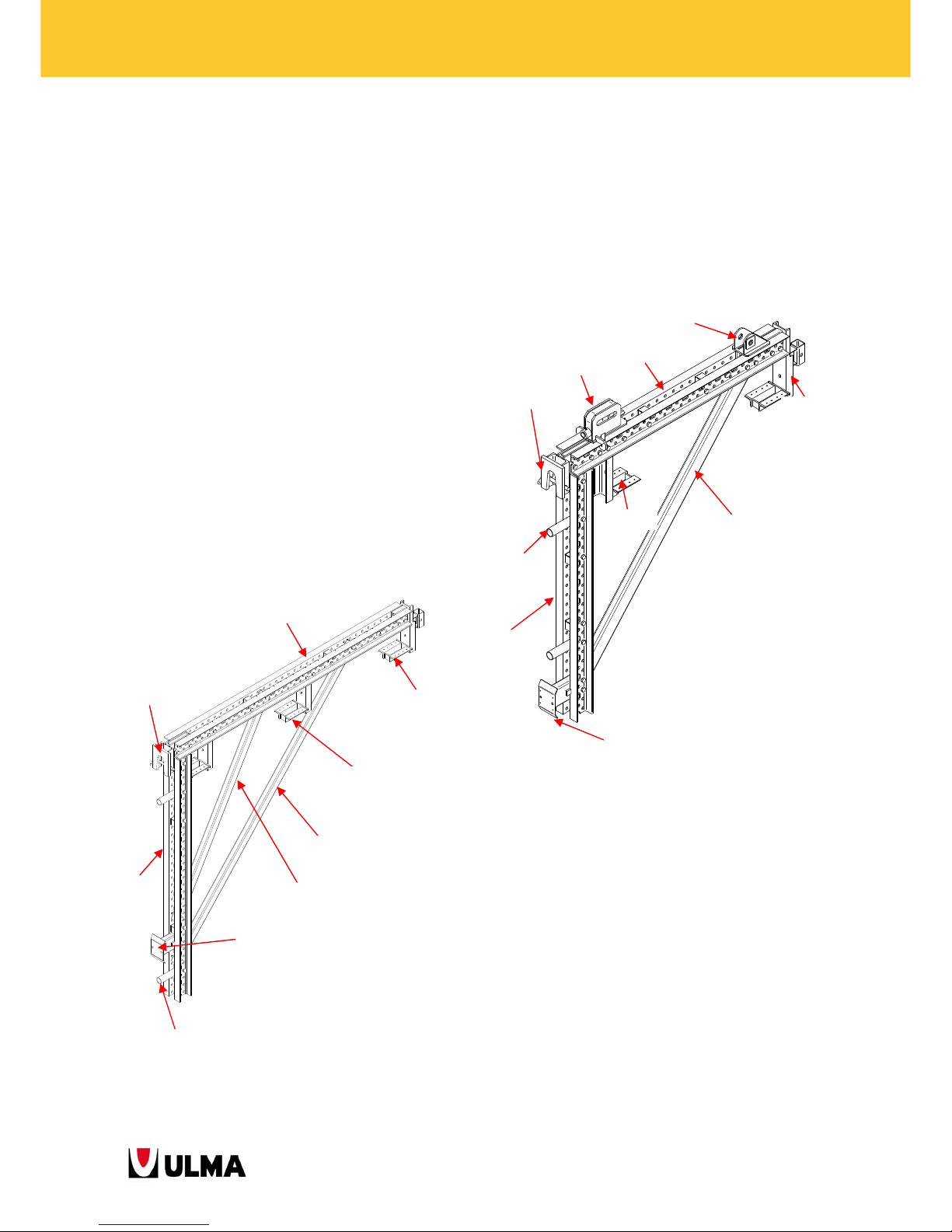
2.2.3. BMK-240 Frame (1991425)
The frame consists of standard walers MK-120 with
different MK accessories bolted and pinned to them.
The following walers are used as:
Horizontal beam: MK-120/ 2.375-1990219
Vertical beam: MK-120/ 2.125-1990217
All accessories except for the diagonals are fastened
to the walers MK with Bolts M16x90 (0241690) and
Locknuts M16 (0241608). The diagonals are fastened
with the following Bolts M20x100 (0242010) and
Locknuts M20 (0242008).
The system offers high flexibility as the accessories
can be easily relocated to different positions along
the waler MK and even different accessories of the
MK system can be bolted to the climbing bracket.
2.2.4. Climbing bracket BMK-170 (1991417)
This bracket can get equipped only with the fixed
stripping configuration.
The waler MK-120/1.625 is used as horizontal as well
as vertical beam. It moreover consists of the Tilt-Back
MK-120 (199467) and Push-Pull Prop Head MK-120
(1991439).
2.2.5. Hinged BMK-240 Bracket (1991465)
It consists of standard walers MK-120 with different
accessories bolted and pinned to it.
The walers used are:
Horizontal beam: MK-120/ 2.375-1990219
Vertical beam: MK-120/ 2.125-1990217
All accessories except for the push-pull prop are
fastened to the walers MK with Bolts M16x90
(0241690) and Locknuts M16 (0241608). The pushpull prop is joined to the Push-Pull Prop Head MK120 (1991439) with Pins 32x150 (0253215) and
Cotter Pins R/5 (0250000).
1990219
1991434
1991427
1990482
1990485
1991410
1990570
1990217
1991487
1990213
1991439
1991434
1990498
1991427
1991410
1991487
1990213
1991467
1990570
Page 15
15
BMK CLIMBING BRACKETS
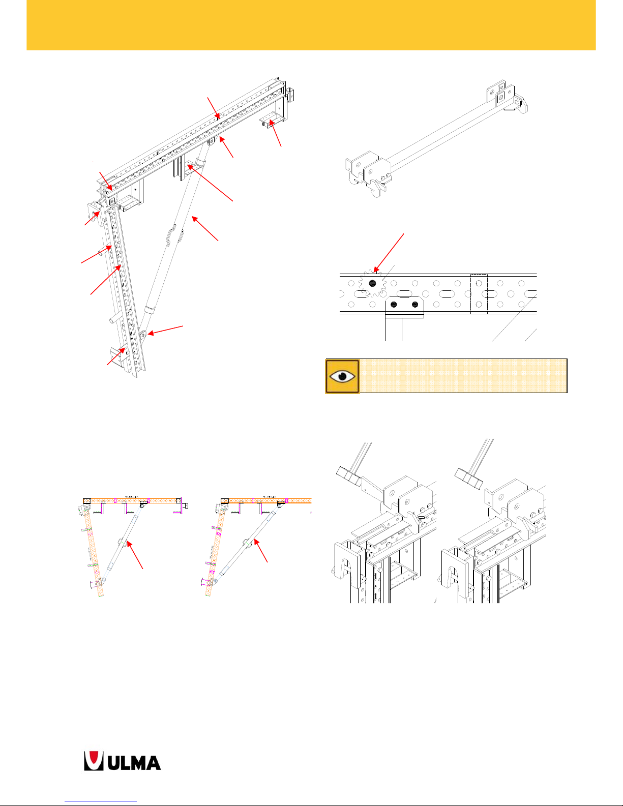
For the cases that the angle is greater than 90º, the
Push-Pull Prop TR63x6 2.04-2.72 (0333014) is used
instead of Push-Pull Prop TR63x6 1.52-2.2
(1991514).
2.2.6. Roll-Back Carriage MK (1991444)
This item slides along the horizontal beam of the
climbing bracket. Connected to the formwork panel,
it moves the panel back for stripping.
Before working on the climbing bracket, the carriage
must get blocked with the incorporated wedge.
For out-of-service cases and whenever moving the
climbing bracket with crane, the carriage must be
fixed with the safety item Gear Locker MK (1991510).
To ensure the correct working of the Roll-Back Carriage, the
Gear MK must be positioned at the place indicated in the
assembly drawings of the Climbing Brackets.
1991514
0333014
1990219
1991434
1991427
1991514
1991410
1990217
1990570
1991503
1991439
1991439
1991487
1 Gear MK (1991456)
1 Gear Shaft MK (1991457)
1 Spring Pin Ø5x30 DIN-1481
Page 16
16
BMK CLIMBING BRACKETS
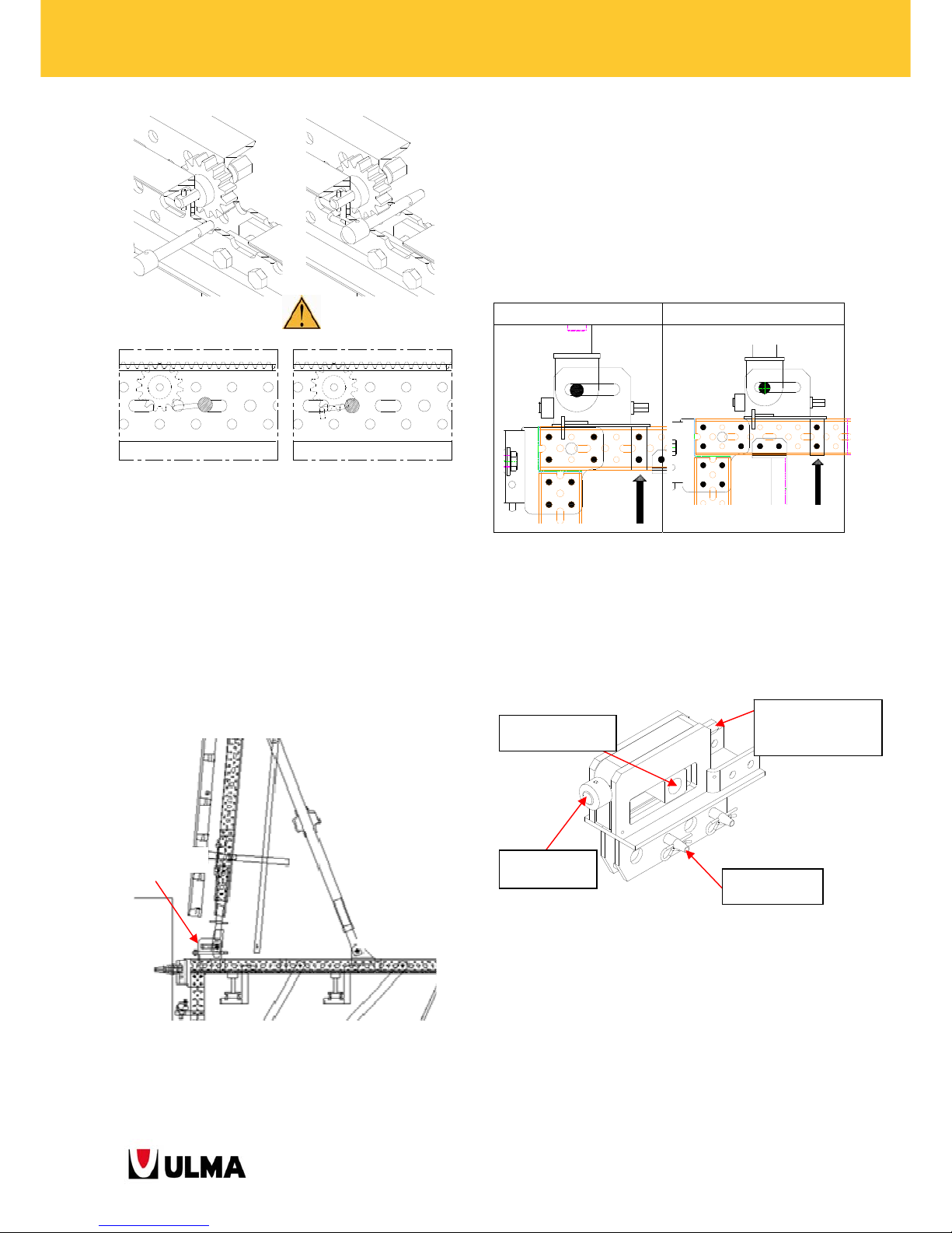
Unblocked position Blocked position
2.2.7. Tilt-Back MK-120 (1991467)
Whenever there is no necessity for a stripping
distance as wide as the one provided by the Roll-Back
Carriage, the Tilt-Back MK-120 system is used.
This item separates the formwork from the wall by
approximately 5 cm and subsequently tilts it.
The Tilt-Back MK-120 (1991467) is fastened to the
bracket frame with Bolts M16x90 (0241690) and
Locknuts M16 (0241608).
Depending on the formwork type used, the Tilt-Back
MK-120 is placed at different positions, the standard
one is the position of the ENKOFORM VMK.
2.2.8. Inclined Tilt-Back MK-120 (1991463)
It is used with the Hinged BMK-240 Bracket
(1991465) in cases where the inclination of the wall
is above 5º (at the side of the inclined formwork).
It enables the detachment of the formwork from the
wall by 5 cm. It is joined on one side to the vertical
waler with Pin w/Head D34x135 and on the other to
the climbing bracket frame.
By adjusting the screw jack for stripping, the mobile
nut is caused to slide along the slot. The Pin D34
inserted into the mobile nut and connected to the
Formwork ORMA Enkoform VMK
Tilt-Back MK-120
(
1991467)
Screw jack - 24 mm
width across flats
MOBILE NUT
STOP-END
NUT
PIN E20x70
Page 17
17
BMK CLIMBING BRACKETS
vertical waler drags the vertical waler with the
attached formwork away from the wall.
The position of the inclined tilt-back differs with
respect to the formwork type and wall geometry
(changes in sections, etc.). Therefore, the positioning
of the pins along the horizontal beam of the
climbing bracket must be studied individually for
each project.
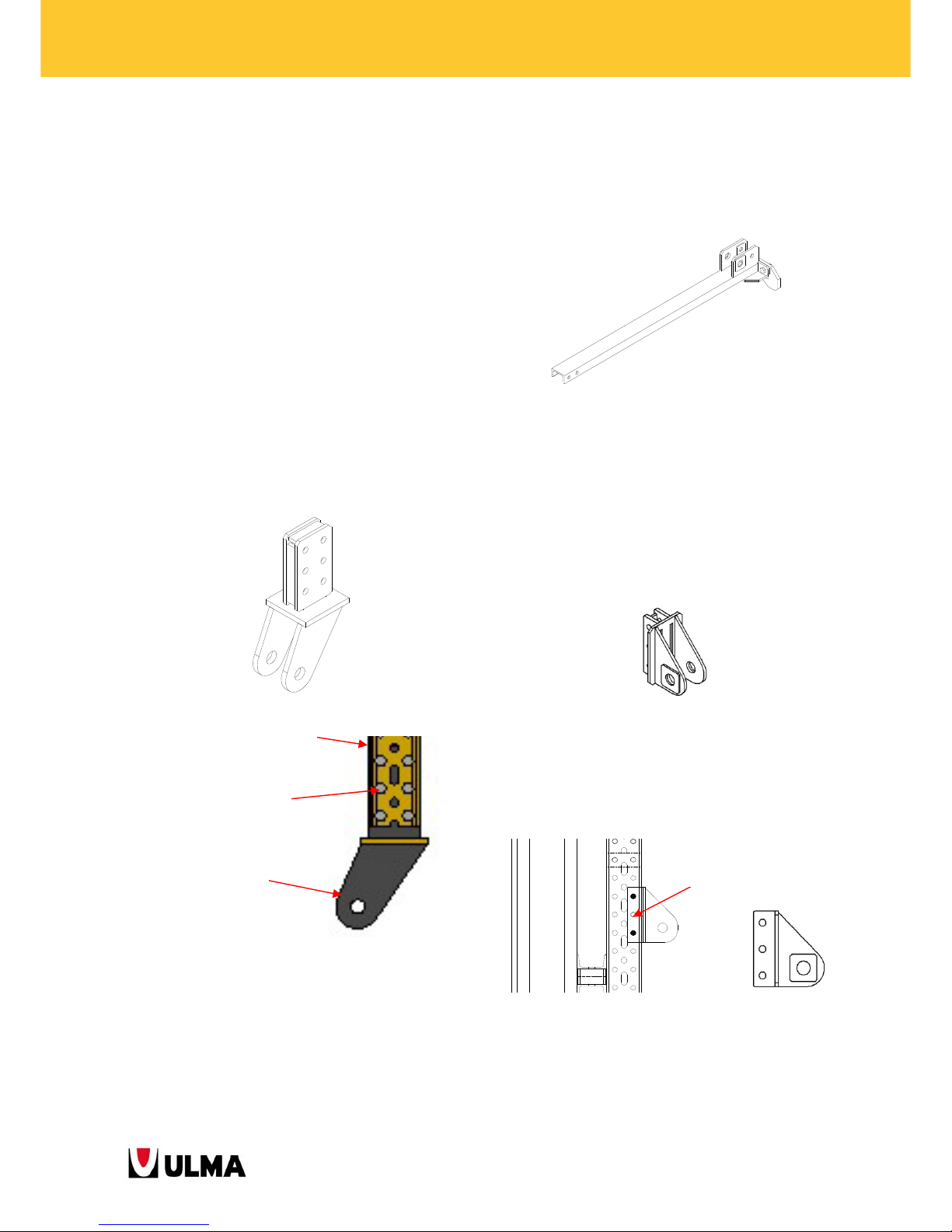
2.2.9. Single Sided Connector MK-120
(1991593)
This part is bolted to the waler MK-120 at one end
and pinned to the Inclined Tilt-Back MK-120 at the
other with a Pin w/Head D34x135.
One feature of this item is that is can be assembled in
both directions depending on the formwork used.
2.2.10. Rack Assembly MK-120 (1991450)
It is a sub-assembly of the Roll-Back Carriage MK-120
(1991444) and is used in combination with the TiltBack MK-120 (1991463) for inclined wall solutions.
The joint with the Tilt-Back MK-120 is fastened with
2 Bolts M16x140 DIN 931-8.8 (0241690), 2 Nuts
M16 DIN-934-8.8 (0241600) and 2 Washers A16
DIN-125 (0241601).
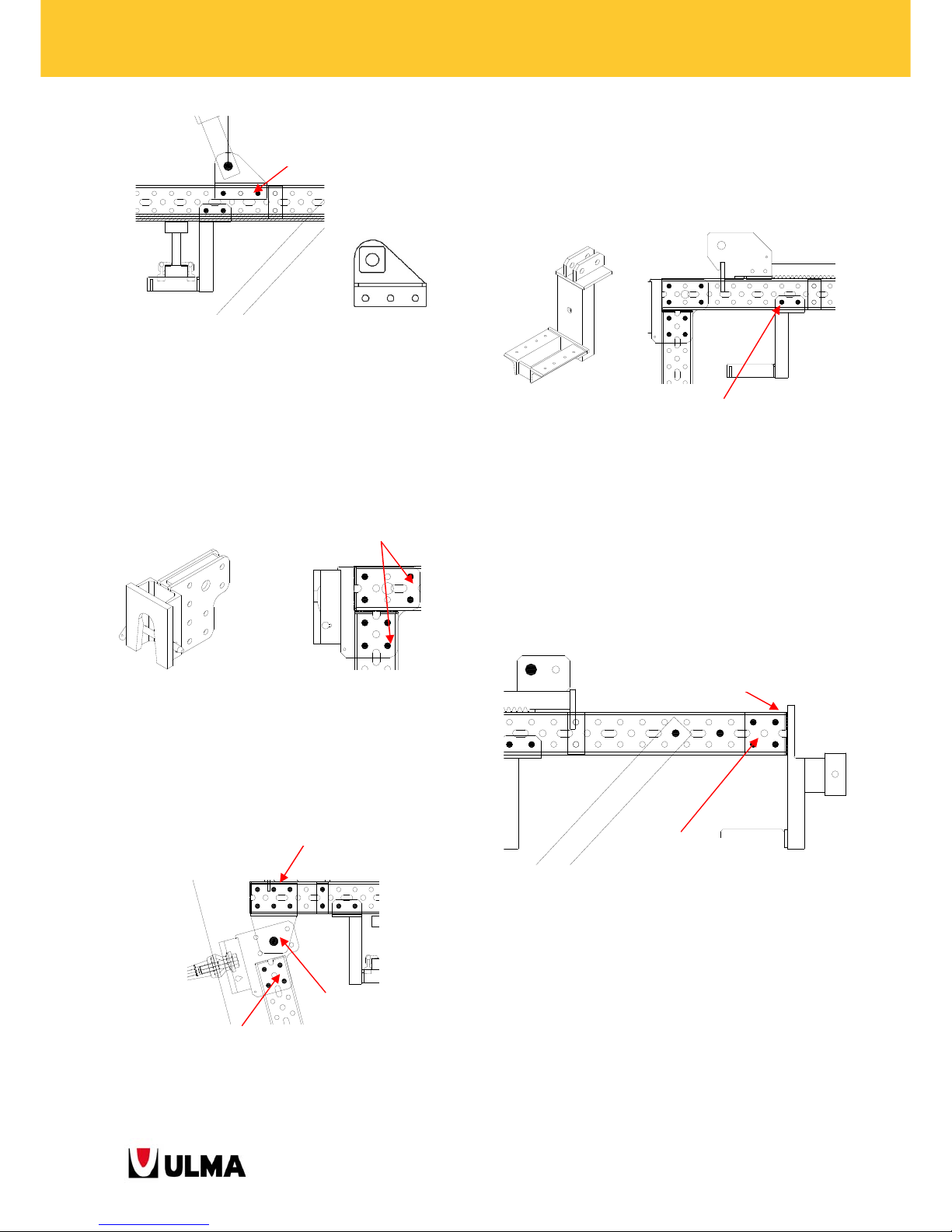
2.2.11. Push Pull Prop Head MK-120 (1991439)
This part is used to connect the push-pull prop with
the waler MK-120.
It is usually fastened to the vertical waler as well as
on the horizontal beam in the case of the climbing
bracket BMK-170 and the Tilt-Back MK-120 with
BMK-240 and BMK-220 Frames.
Head on vertical waler
2 Bolts M16x90 (0241690)
Waler MK-120
6 Bolts M16x90 (0241690)
6 LockNuts M16
(
0241608)
Single Sided Connector
M
K
-120 (1991593)
Page 18
18
BMK CLIMBING BRACKETS
Head on horizontal beam of BMK-170
It is also used for inclined wall solutions.
2.2.12. Right Angle Head (1991410)
Head to support the climbing bracket on the wall
anchorages. The included safety pin prevents it from
disengaging from the anchorage.
2.2.13. MK Hinged Head (1991503)
This head does the same for inclined wall
applications, until walls with a maximum slop of
±15º.
2.2.14. Platform Support MK-120 (1991427)
Item to which the beams or walers are assembled to
form the platform. It is fastened to the waler with
bolts M16.
2.2.15. Platform Back Support MK-120
(1991434)
Item placed at the back part of the climbing bracket
to assemble the platform. It is fastened to the waler
with bolts M16.
The Platform Back Support MK-120 has a ledge
incorporated to prevent the carriage from
disengaging from the horizontal waler.
2 Bolts M16x90 (0241690)
2 L
ockNuts
M16 (0241
608)
8 Bolts M16x90 (0241690)
8 Lo
ckNuts M16 (0241
608)
4 Bolts M16x90 (0241690)
4 L
o
ckNuts M16 (0241
608)
Ledge
1 Pin 32x150 (0253215)
2 Cotter Pins R/5 (0250000)
6 Bolts M16x90 (0241690)
6 LockNuts M16
(
0241608
)
4 Bolts M16x90 (0241690)
4 LockNuts M16
(
0241608)
2 Bolts M16x90 (0241690)
2 LockNuts M16 (0241608)
Page 19
19
BMK CLIMBING BRACKETS
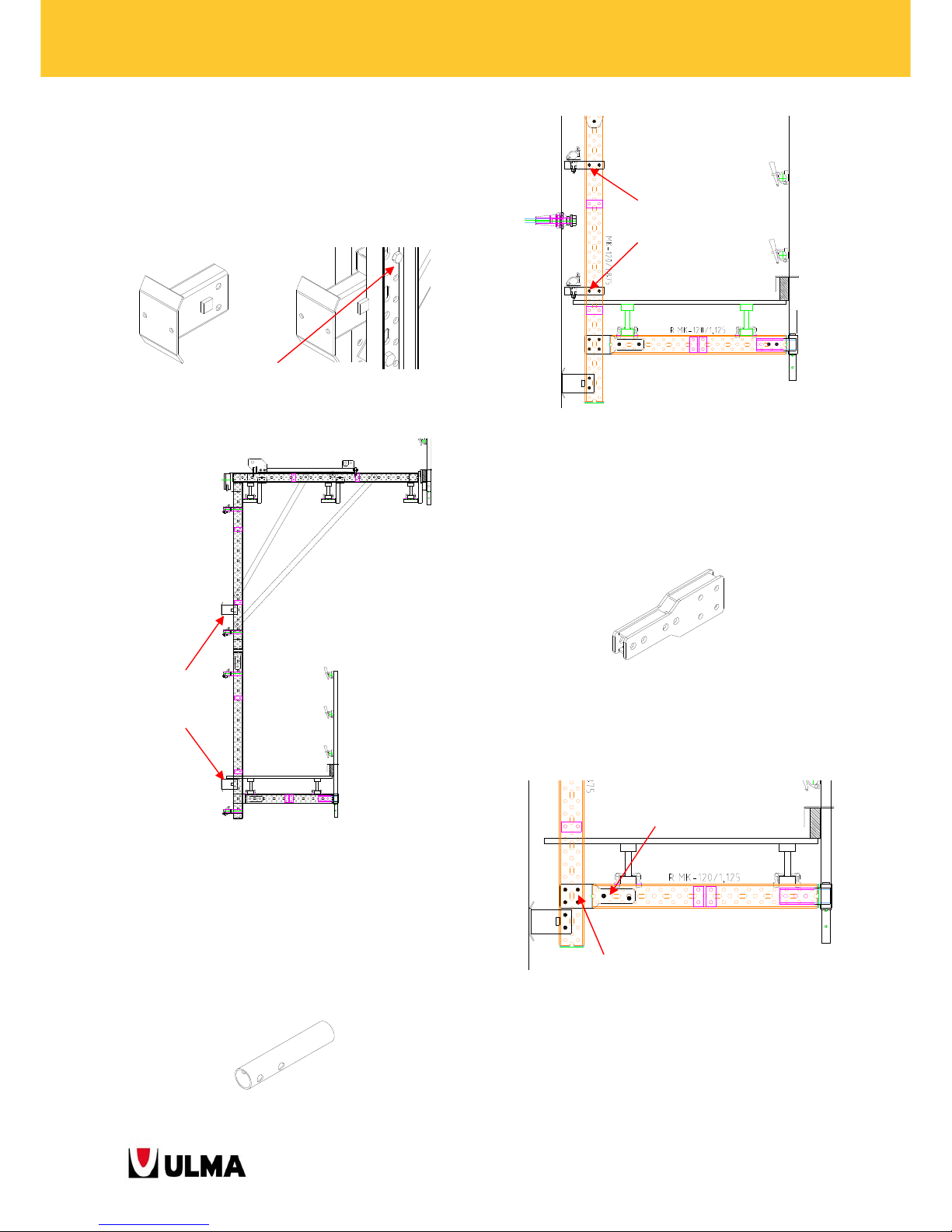
2.2.16. Bottom Support (1991487)
This accessory is placed on the vertical waler of the
main platform and on the waler MK used for the
cone recovery platform.
2.2.17. Handrail Head MK (1990570)
Tube which serves as support for the couplers of the
climbing bracket bracing and for the walers of the
cone recovery platform.
2.2.18. Axial node M2-D20 MK (1991458)
This part is a joint used for the creation of the
platforms (pouring/ intermediate/ cone recovery).
The Axial Node M2-D20 MK is bolted to the waler
MK according to the pouring height.
Bottom Support
(1991487)
2 Bolts M16x90 (0241690)
2 LockNuts M16
(
0241608)
2 Pins E20x70 (0252070)
2 Cotter Pins R
/5 (
0250000)
4 Bolts M16x90 (0241690)
4 LockNuts M16
(
0241608)
2 Bolts M16x90 (0241690)
2 L
o
ckNuts M16 (0241
608)
Page 20
20
BMK CLIMBING BRACKETS
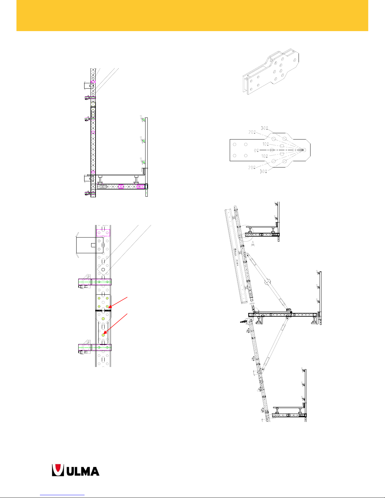
It is also used to connect the main platform to the
cone recovery platform.
2.2.19. Walkway Hinged Connector (1991476)
This part is a joint used for the creation of the
platforms for inclined wall solutions. With this
connector, the platforms are kept in horizontal plane.
Covers inclinations of ±10º - 20º - 30º
2 Pins E20x70 (0252070)
2 Cotter Pins R
/5 (
0250000
)
4 Bolts M16x90 (0241690)
4 LockNuts M16
(
0241608
)
Page 21
21
BMK CLIMBING BRACKETS
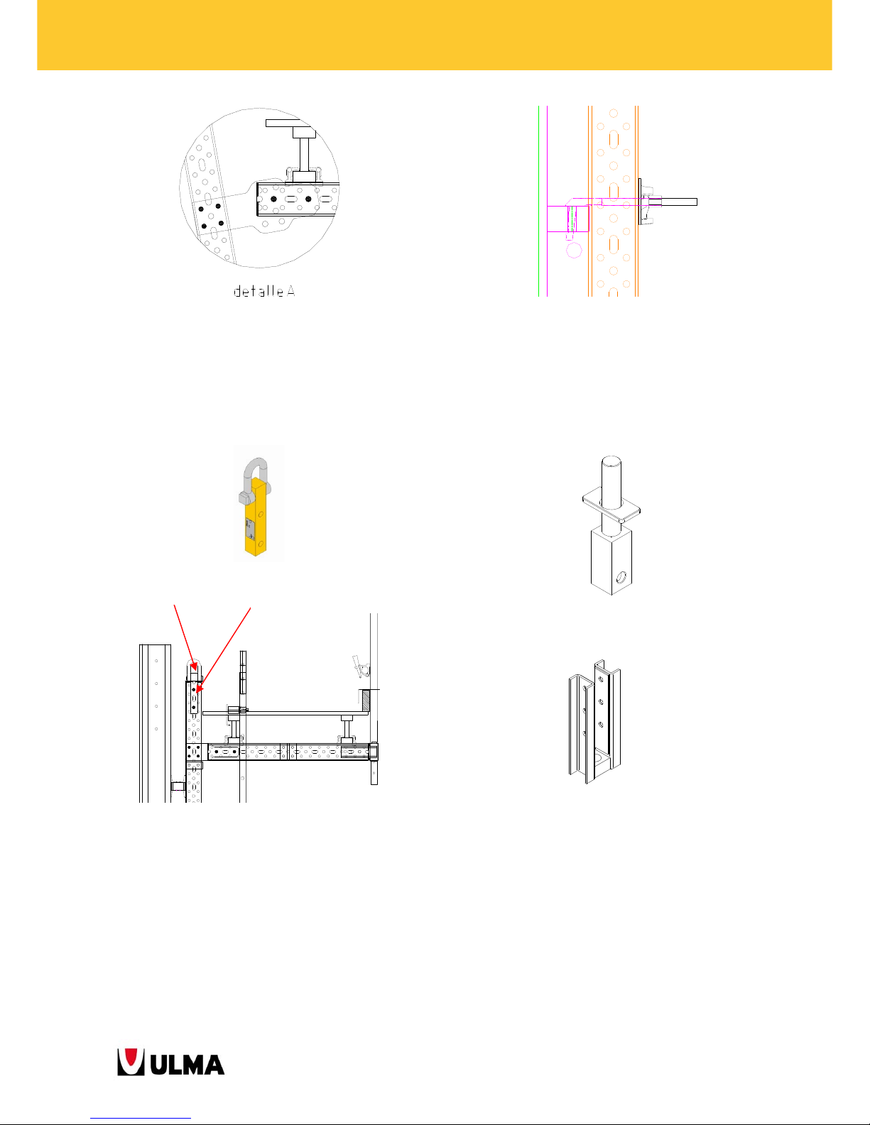
2.2.20. Lifting Hook MK (1991360)
Item used to lift the structure. It is joined to the top
part of the vertical waler (waler MK) fastened with 2
Pins E20x70.
2.2.21. Waler Hook (1900448)
Connection part between vertical walers and ORMA
formwork panels.
2.2.22. Waler Screw TR53x6 (0302020)
This part joins the vertical waler with the Roll-Back
Carriage and enables height adjustments.
The following parts are required for the joint.
1991570 – Waler MK-120 Screw Bracket : This
item connects the screw jack with the vertical
waler.
1 Lifting Hook MK (1991360)
2 Pins E20x70 (0252070)
2 Cotter Pins R/5 (0250000)
Page 22
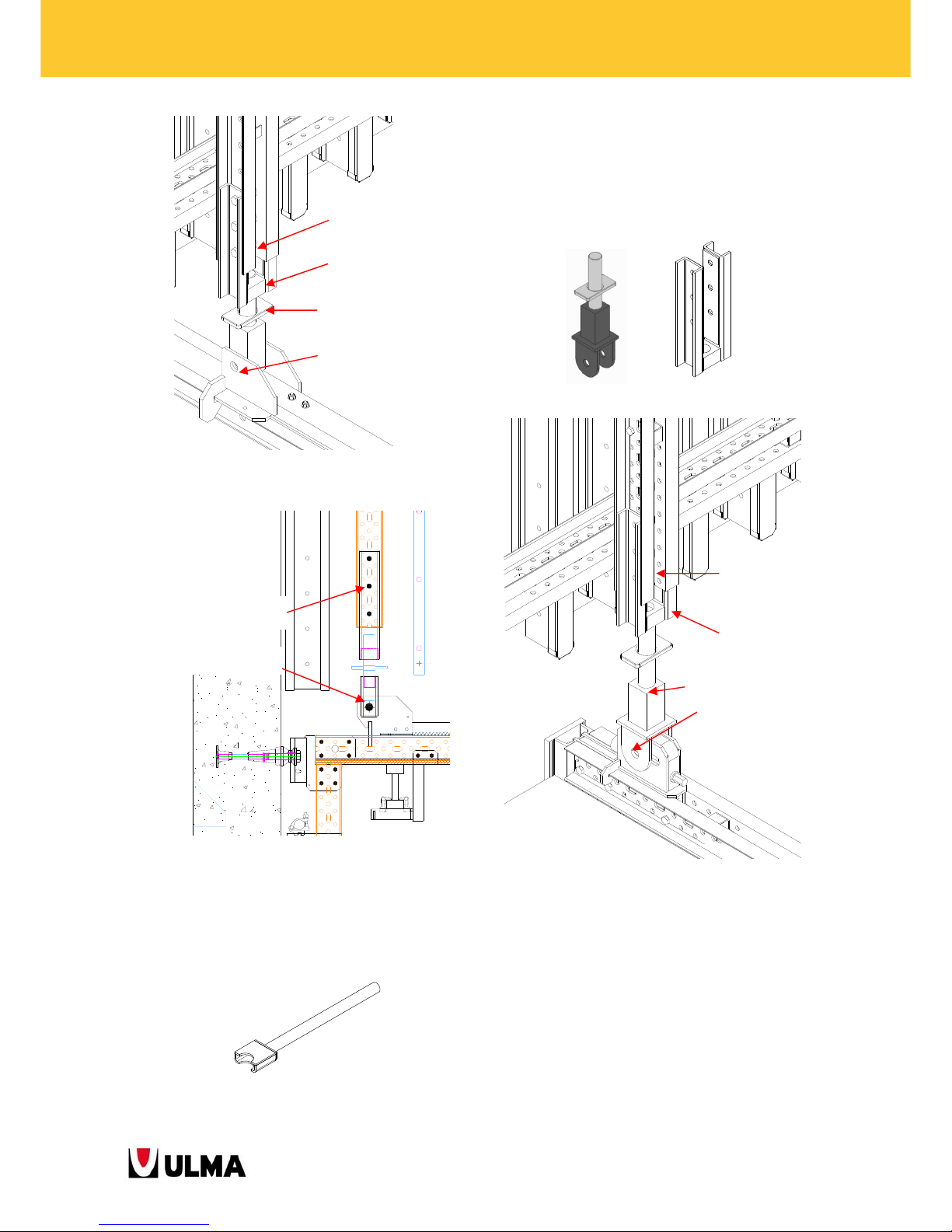
22
BMK CLIMBING BRACKETS
To operate the screw:
0331013- Handle screw TR53. This item
introduced into the plates makes easier to
move it.
2.2.23. Connector MK Screw Waler Base (1991517)
This part connects the vertical waler with the TiltBack MK-120 (1991467). This way the panel height is
adjusted with the screw jack.
2.2.24. Clamp M20x330 (0260001)
It is used to join two walers, primarily the vertical
waler to the horizontal waler of ENKOFORM
formwork.
3 Pins D20x100 (0335153)
3 Cotter Pins R/5 (0250000)
1 Pin D32x150 (0253215)
2 Cotter Pins R/5 (0250000)
3 Pins D20x100 (0335153)
3 Cotter pins R/5 (0250000)
Connector MK Screw Waler Base
Waler MK-120 Screw
Bracket
1 Pin D32x150 (0253215)
2 Cotter Pins R/5 (0250000)
3 Pins D20x100 (0335153)
3 Cotter pins R/5 (0250000)
Waler Screw TR53x6
Waler MK-120 Screw Bracket
1 Pin D32x150 (0253215)
2 Cotter Pins R/5 (0250000)
Page 23
23
BMK CLIMBING BRACKETS
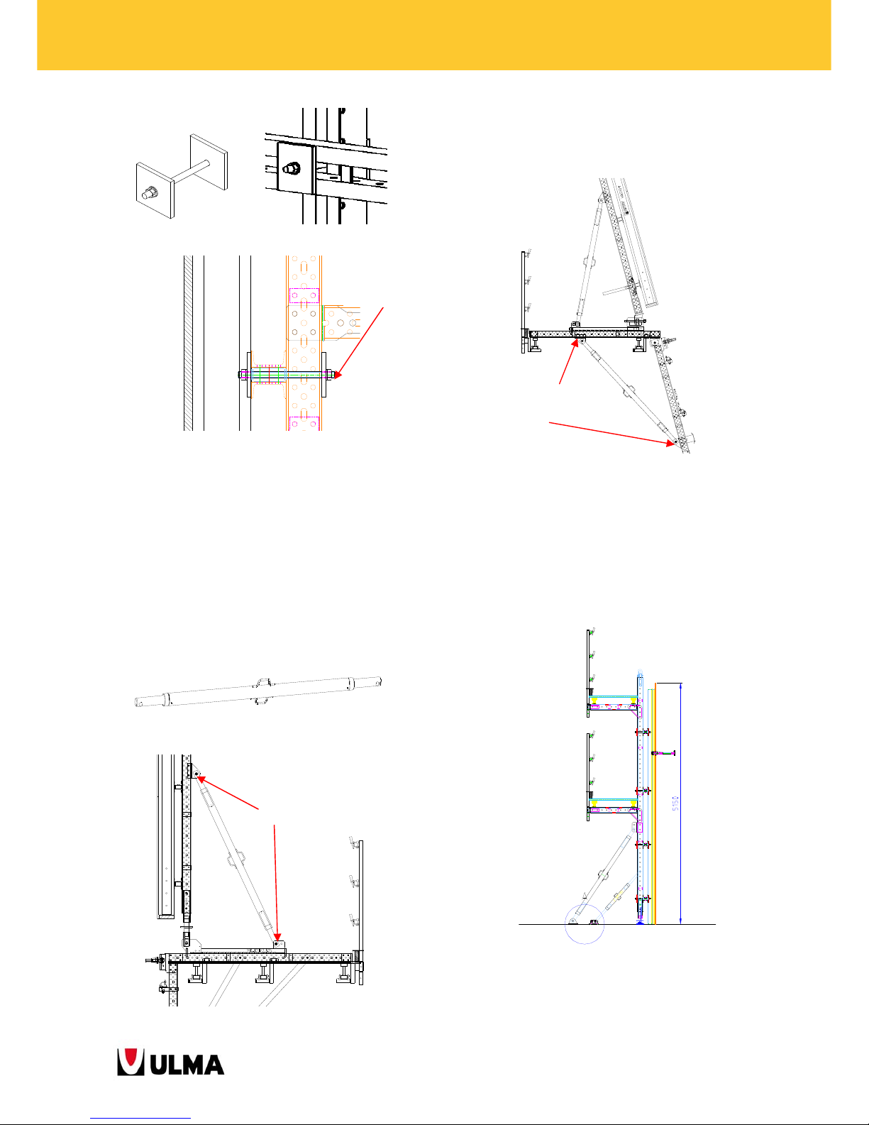
2.2.25. Push-Pull Prop TR63x6 2.04-2.72
(0333014)--Push-Pull Prop TR63x6 1.52-2.2
(1991514)
These props are used to plumb and strip the panels
by connecting the vertical walers with the climbing
bracket.
It is also used as diagonal for the hinged climbing
bracket.
2.2.26. Push-Pull Prop Shoe TR63 (0333055)
and Push-Pull Prop E Shoe 2 D20x48 (1960545)
These shoes are used to stabilise the panel of the
vertical formwork at the first pouring stage on the
ground.
2 Pin D32x150 (0253215)
4 Cotter Pins R
/5 (
0250000
)
2 Pin D32x150 (0253215)
4 C
otte
r Pins R/5 (02
50000)
Clamp M20x330
(0260001)
Page 24
24
BMK CLIMBING BRACKETS
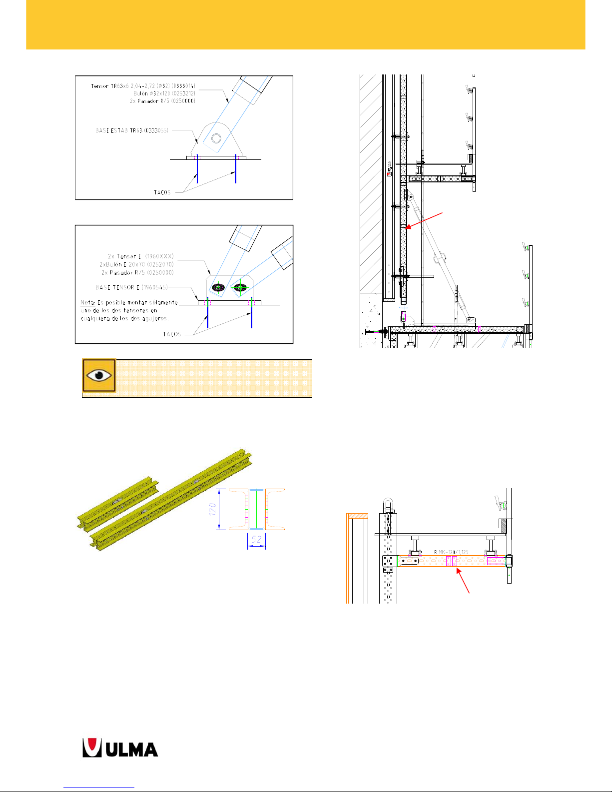
2.2.27. Walers MK-120
The main applications of the Waler MK-120 are the
following:
- As vertical waler: vertical connection beams
between the formwork and the climbing bracket
BMK.
The lengths used depend on the formwork height.
- As part of concrete pouring, vertical waler and
cone recovery platform: transversal beams on
which the timber beams VM20 are placed parallel
to the wall. The most commonly used waler length
is the Waler MK-120/1.125 (1990209). It is
fastened with the Axial Node M 2-D20 MK
(1991458).
- As part of the cone recovery platform:
longitudinal beams, fastened to the climbing
bracket with Pins E20x70.
The lengths used depend on the pouring height.
Waler MK-120/1.125 (1990209)
Waler MK-120
To validate the use of these shoes, see the User's Guide
Push-Pull Prop Shoes.
Page 25
25
BMK CLIMBING BRACKETS
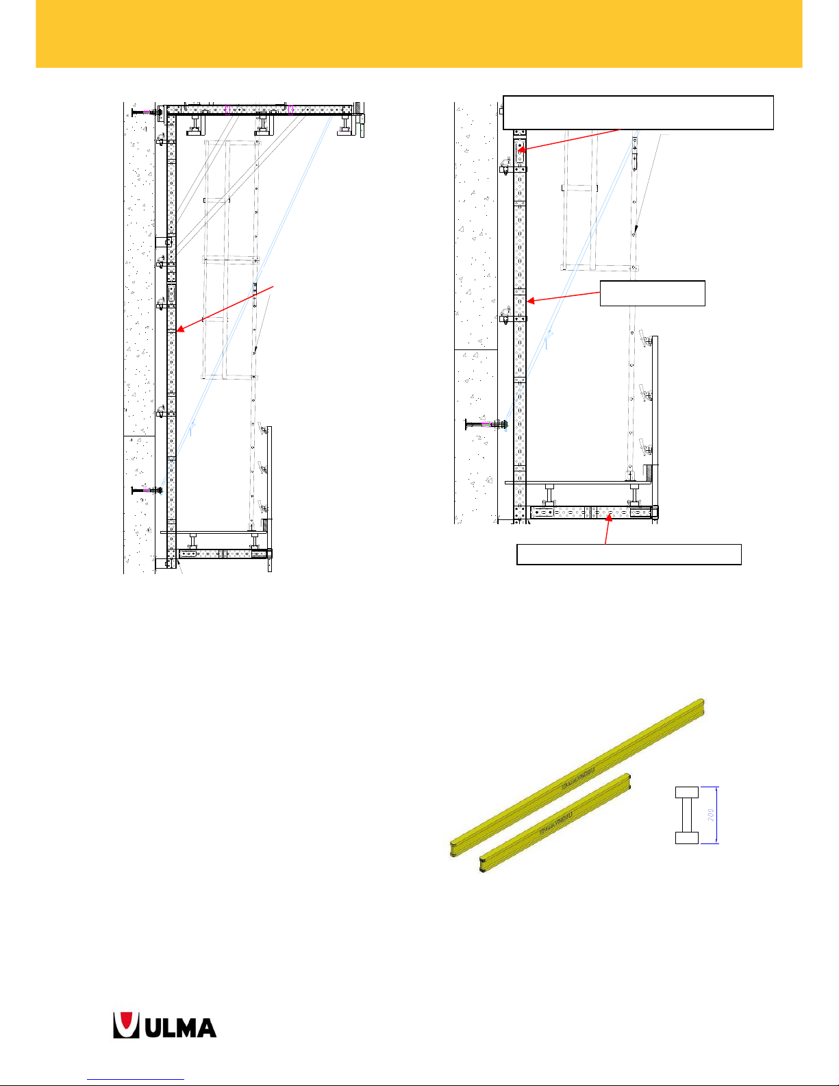
2.2.28. Profiles MK-120
The range of Profiles MK-120 can be used to replace
the Walers MK-120 as vertical beam of the cone
recovery platform.
With the same accessories, the profile is placed on
the side of them and is fastened with bolts and nuts.
2.2.29. Timber Beams VM20
Timber beams are used to deck all working
platforms.
Waler MK-120
Waler MK-120/1.125 (1990209
)
2 Bolts M20x80 DIN931- 8.8 (0242080)
2 LockNuts M20 DIN985 - 8
(
0242008
)
Profile MK-120
Page 26
26
BMK CLIMBING BRACKETS
These are the item numbers and available lengths:
Item no. Length Item no. Length
1940172 1.90m 1940146 3.60m
1950129 2.45m 1950112 3.90m
1940144 2.90m 1950113 4.90m
1950130 3.30m 1940149 5.90m
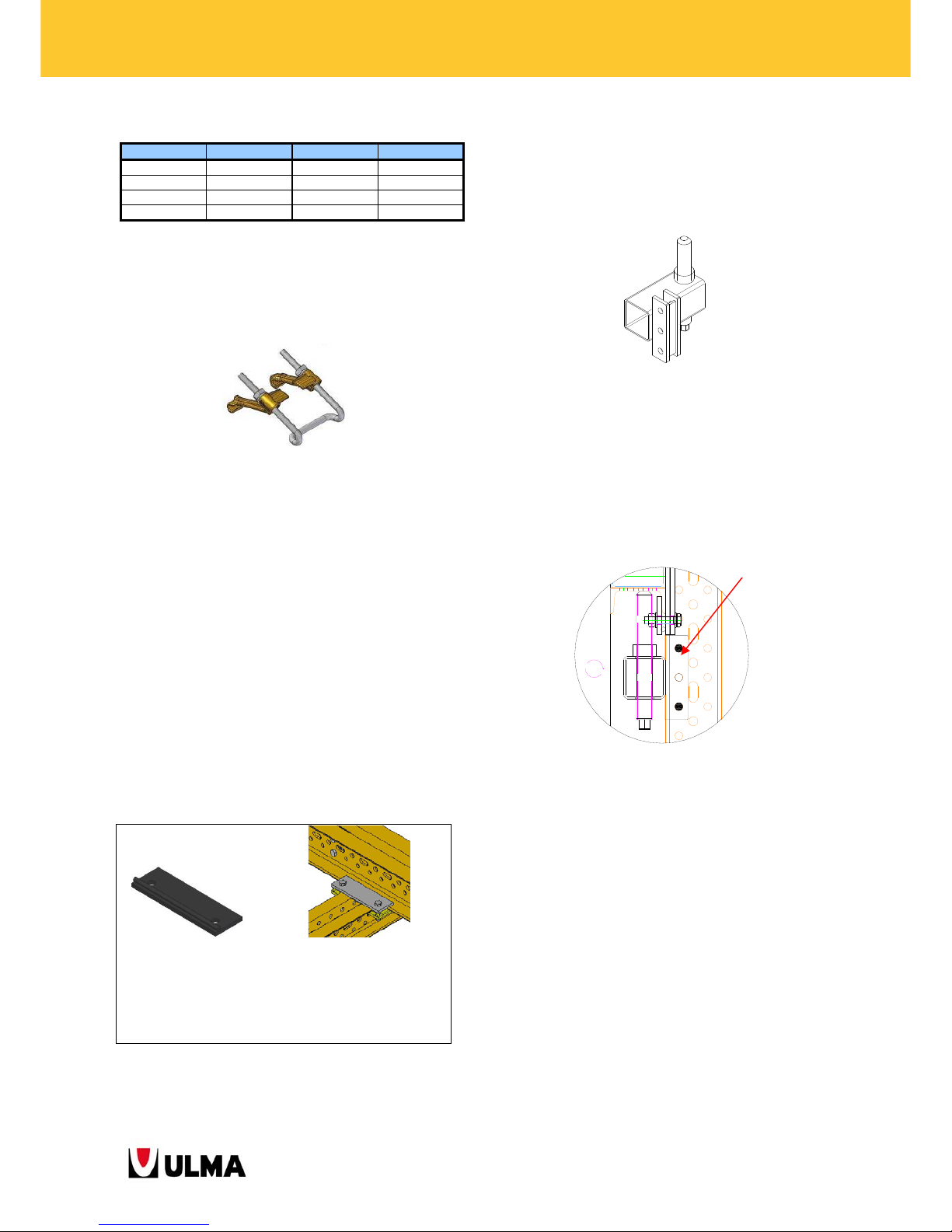
2.2.30. Waler-VM20 Clamp 2T (1960375)
Part to tie the timber beams VM20 to the walers.
2.2.31. Platform board
The beams VM20 of the platforms are commonly
covered with planks or 3-layer board.
These are the main sizes of the 3-layer-board used:
- 3-Layer Board of 2000x503x27 (7251132)
- 3-Layer Board of 2500x500x27 (7251136)
The board is fixed to the timber beams with Screws
6x60 DIN-7505-A (0249911).
2.2.32. Plate Clamp DU-DU
It is used to join two walers MK-120 at 90º.
2.2.33. Adjustment Jack MK-120 (1991567)
It is used to prevent any possible vertical movement
of the formwork.
It is fastened to the vertical walers (MK-120) with 2
bolts placed the way that the horizontal walers
support on the jacks.
2.2.34. Handrail Post 1.5 (2211156) and
Handrail Post 1.5 Wood (2211185)
They form part of the handrail system of the climbing
brackets. Posts to which tubes or planks are
connected thus providing a handhold.
The Handrail Post 1.5 has wedges to ease the
assembly of the tubes.
It is inserted into the respective handrail support. The
toeboard is hold by the mobile toeboard bracket.
4 Plate Clamps DU-DU
(0919259)
4 Bolts M16x70 DIN933-8.8
(0241670)
4 Nut M16 DIN934-8 (0241600)
8 Washers A16 DIN125 (0241601)
2 Bolts M16x90 (0241690)
2 Nuts M16
(
0241600
)
Page 27
27
BMK CLIMBING BRACKETS
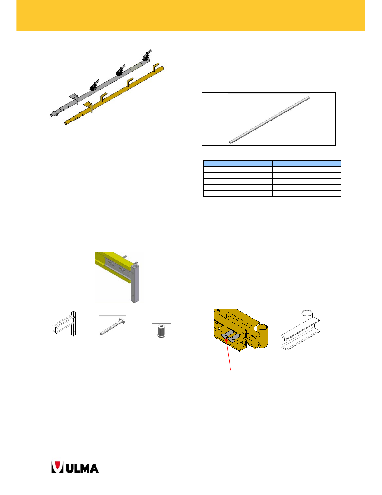
They following handrail post supports are available:
2211165 - VM Handrail Support Long
0121004 - Handrail Socket D50
2.2.35. VM Handrail Support Long (2211165)
Support type used to place handrails onto beams VM
of which the platforms consist. It is tied to the beams
with two Panel Bolts and two Hexagonal Nuts 15.
VM Handrail Support Long Panel Bolt Hexagonal Nut 15
(2211165)
(1861122) (7238001)
Also it is possible to tie with Bolt M16x90
(0241690) + Nut M16 DIN934 (0241600) +
Washer A16 (0241601).
2.2.36. Tube Ø48
Tube serving as handhold for the handrail system of
the different platforms.
These are the item numbers and available lengths:
Item no. Length Item no. Length
2125288 0.50m 2125249 3.10m
2125289 1.10m 2125648 3.60m
2125290 1.60m 2125250 4.10m
2125291 2.10m 2125251 5.00m
2125647 2.60m 0200600 6.00m
The tubes are connected to the wedges incorporated
in the handrail posts.
They are also used as bracing during the initial
assembly stage of the climbing bracket.
2.2.37. Handrail Socket D50 (0121004)
Support type used to place handrails onto walers
MK-120 of which the platforms consist. The socket is
placed inside the waler and fastened with two pins.
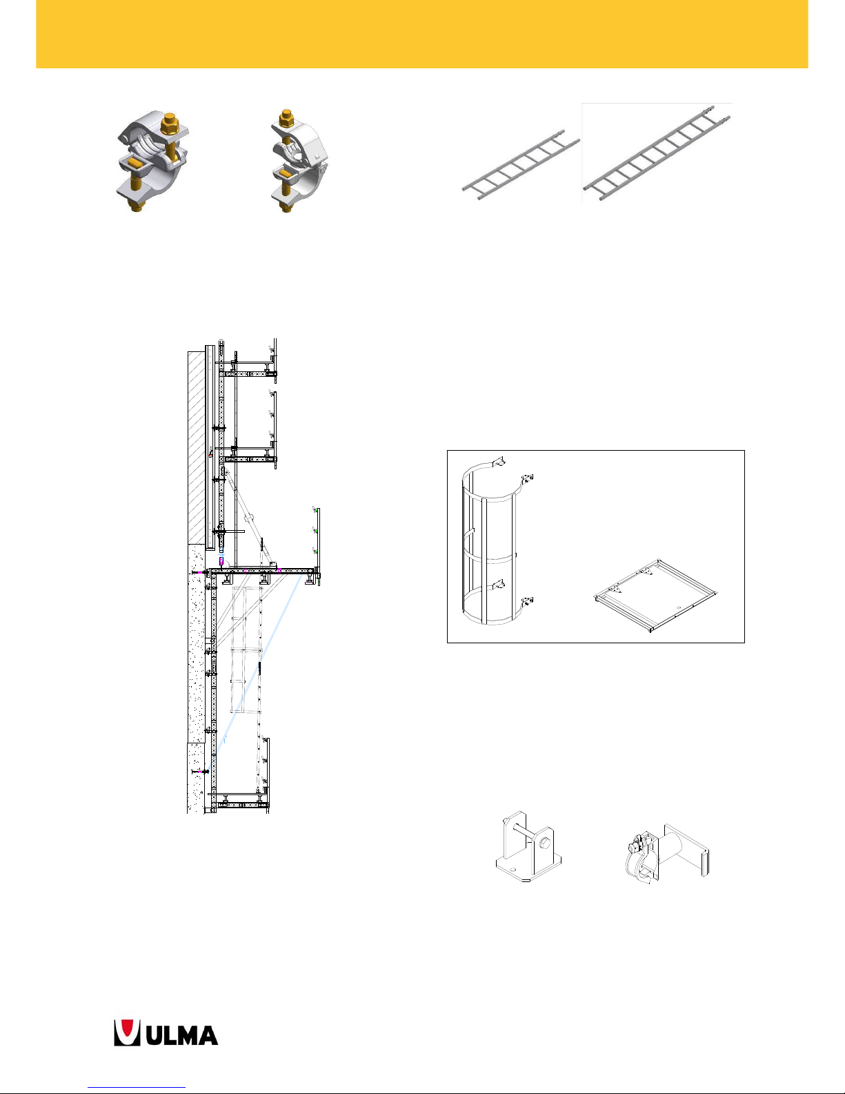
2.2.38. Couplers 48/48
Couplers are used to join two D48 tubes. The right
angle coupler is used to join two tubes
perpendicularly. The swivel coupler is used to join
two tubes at different angles.
Handrail Post 1.5
(2211156)
Handrail Post 1.5 Wood
(2211185)
2 Pins E20x70 (0252070)
2 Cotter Pins R/5 (0250000)
Page 28
28
BMK CLIMBING BRACKETS
2.2.39. Access Ladders between platforms
Ladders provide access to the different working
platforms. This is an example for access ladders:
The ladder C2.1 and the ladder C3 can be used
interconnected or separately depending on the
pouring height.
2.2.40. Ladder Protection (0333012) and
Ladder Hatch (0333013)
When the height is above 2.5 m, Ladder Protection is
placed.
The Ladder Hatch is nailed to the wood of the
working platforms. It eases the access to the
platforms.
2.2.41. Ladder Fixer (0333010) and Ladder
Hanger (0333011)
The Ladder Fixer and the Ladder Hanger are used to
fix the ladder to the working platforms.
Ladder Fixer Ladder Hanger
(0333010) (0333011)
Right Angle
Coupler 48/48
(2125148)
Swivel Coupler
48/48
(2125147)
Ladder C2.1
(0333008)
Ladder C3
(0333009)
Ladder
Protection
Ladder
Ladder
Hatch
Page 29
29
BMK CLIMBING BRACKETS
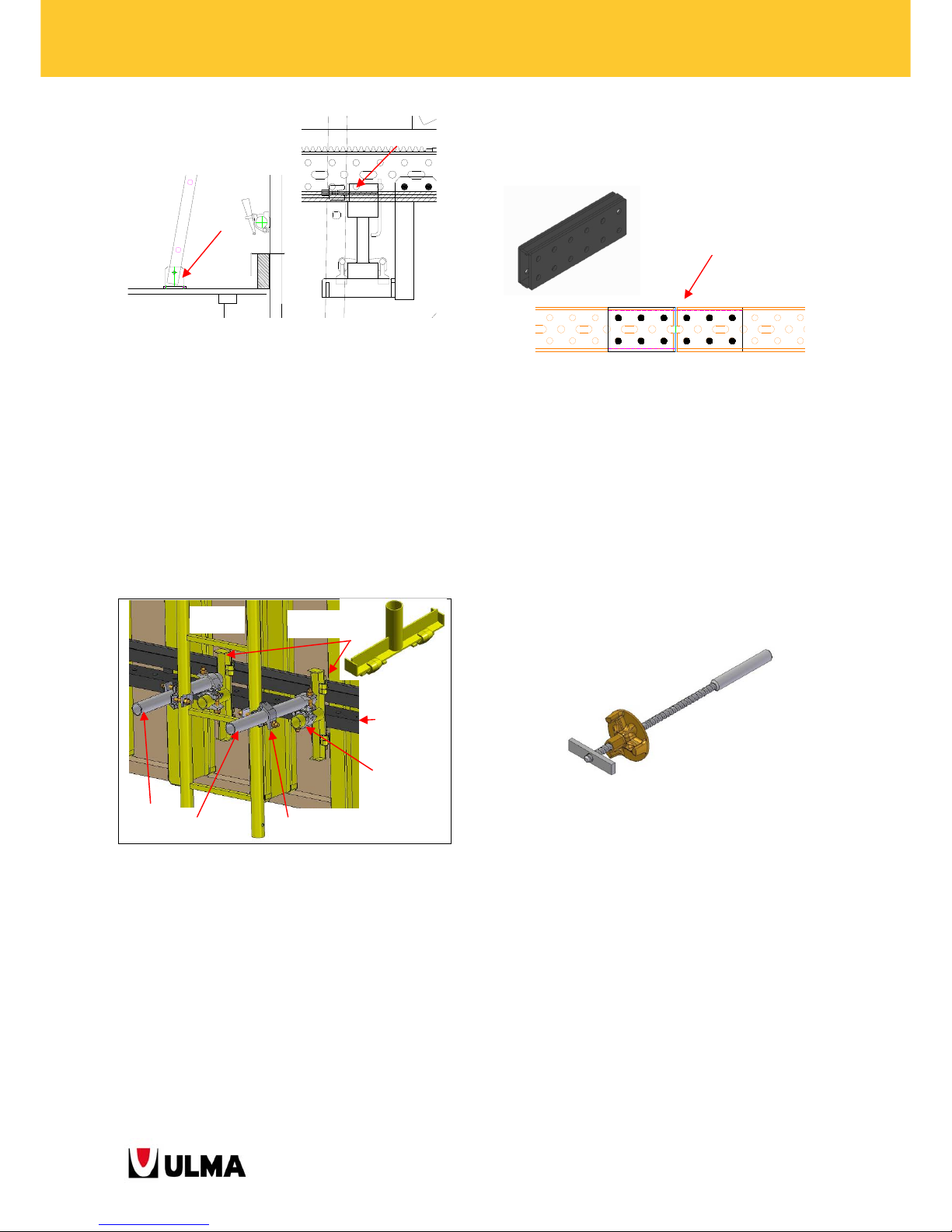
2.2.42. Simple Bracing (0260505)
It is used on the main platform to fix the ladder to
the formwork panel
tied to the lower horizontal waler of the ENKOFORM
panel (for an ORMA panel, another horizontal waler
DU-100 must be placed held with panel bolts).
A tube 48x0.5 connects the Simple Bracing (with
swivel coupler) with the vertical pipe of the ladder
(with right angle coupler).
2.2.43. Orthogonal Joint MK (1990395)
In certain situations, the main platform is decked
with Walers MK-120 instead of Timber Beams VM20.
For those cases, it may also become required to
connect walers lengthwise in order to cover longer
distances. This is obtained with the Orthogonal Joint
MK placed between two walers and fastened with
bolts M16.
2.2.44. Cone-Waler Tie 90 (1901250)
This part consists of a threaded bar M24 at one end
and Dywidag thread along the rest of the bar. A
plate nut runs on the Dywidag thread secured from
disengaging by a stop-end plate.
It is used to hold the anchor components onto
ORMA panels. The ties are inserted into the tie holes
of the panels and into additional holes drilled into
the panel if required.
2.2.45. Wind Sling (0333018) and Wind Sling
Fixer M30 (0333016) or M24 (1901804)
It prevents the overturning of the entire system under
windy conditions. The climbing bracket BMK is fixed
to the wall with the sling.
This sling is tied to the Pin E20X70 of the climbing
bracket BMK and to the anchor cones of the previous
pouring stage.
Ladder
C2.1 or C3
Tube 48x0.5
(2125288)
Waler DU
Simple Bracing
(0260505)
Right Angle
Coupler
Swivel Coupler
48/48 (2125147)
12 Bolts M16x90 (0241690)
12 LockNuts M16
(
0241608
)
Page 30
30
BMK CLIMBING BRACKETS
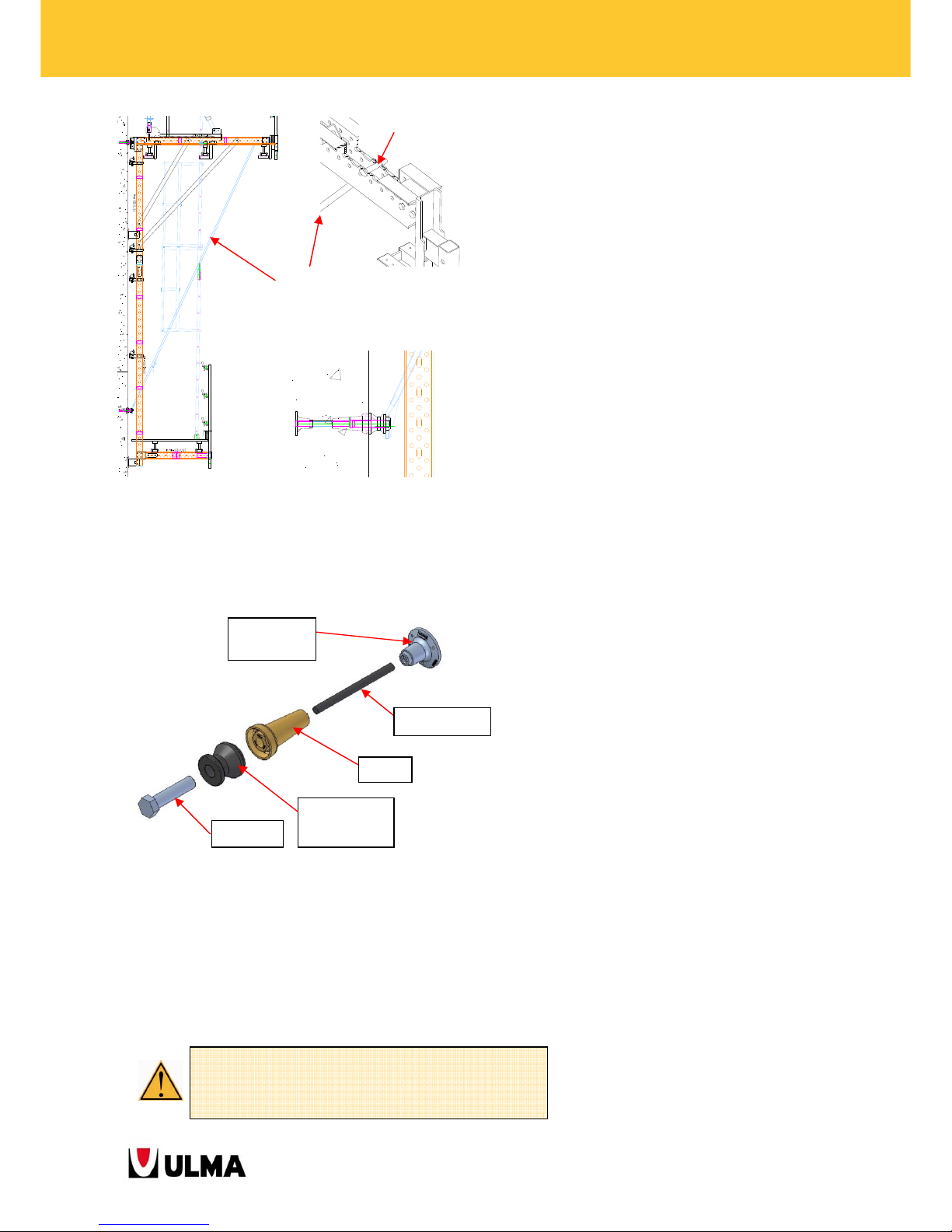
2.2.46. Anchorages
The anchoring system for the climbing brackets
consists of:
Anchorage types DW15 as well as DW20 can be used
with the system. Each case must be studied in terms
of formwork type and area possible to be used.
Note: The reactions of the anchor cone must always
be compared with the anchorage strength and
concrete strength.
Fixed Anchor
DW20
Tie Rod
Cone
Climbing
Ring
Bolt
See working load tables of the anchorages DW15
and DW20.
Pin E20x70 (0252070)
Cotter Pin R/5 (0250000)
Wind Sling (0333018)
Page 31

31
BMK CLIMBING BRACKETS
3. ASSEMBLY, USE AND DISMANTLING
Allow for an adequately sized and level working area to ease the correct assembly of the climbing system.
Subsequently, general guidelines for the assembly, use and dismantling of the system are described in detail.
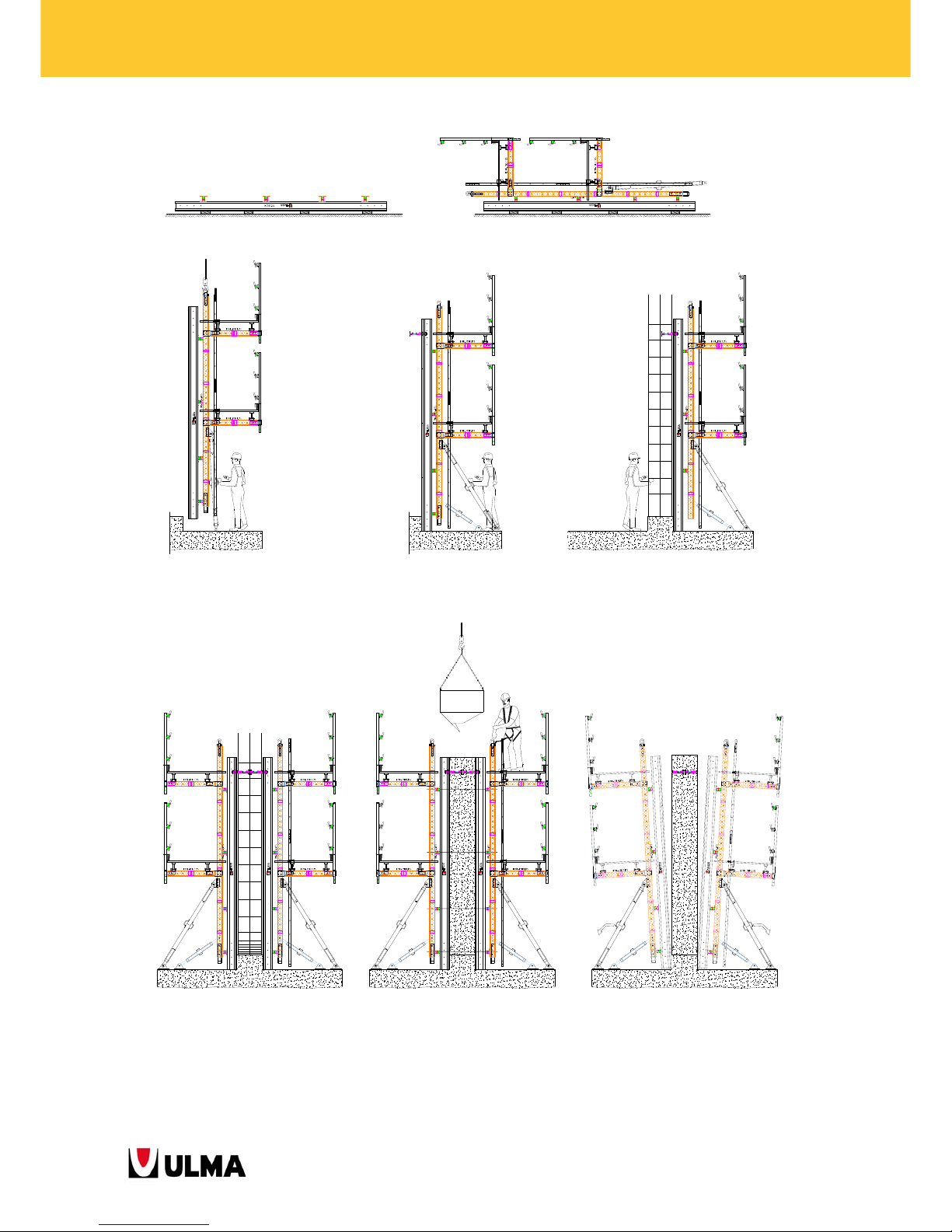
3.1. Instructions for the Climbing Bracket BMK system: First pouring stage on the
ground
1. Assemble the formwork panels according to the instructions given below.
2. Fix the vertical walers to the formwork making sure that the distance between the walers is the same as the
one between the cones. Bolt the walkway bracket onto the vertical walers to complete the platforms. The
position of the platforms on the vertical waler depends on the pouring height.
3. Lift the structure and position it in the indicated location.
4. Place Base Plates and Push-Pull Props to plumb the formwork panel. Fasten the Base Plates. Do not let go of
the panel with the crane until having anchored the formwork properly to the ground. Position the anchor
cones to support the climbing system during the next pouring stage according to the indications in the
assembly drawings.
5. Apply release agent and place the steel reinforcement.
6. Position the rest of the formwork panels.
7. Place tie rods along the rows of walers and pour the concrete according to the project.
8. Remove the tie rods and proceed with stripping by adjusting the push-pull props. Before actually removing the
panels, place the climbing rings onto the cones from the concrete pouring platform. Remove the panels.
Page 32
32
BMK CLIMBING BRACKETS
1 2
3 4 5
6 7 8
Page 33
33
BMK CLIMBING BRACKETS
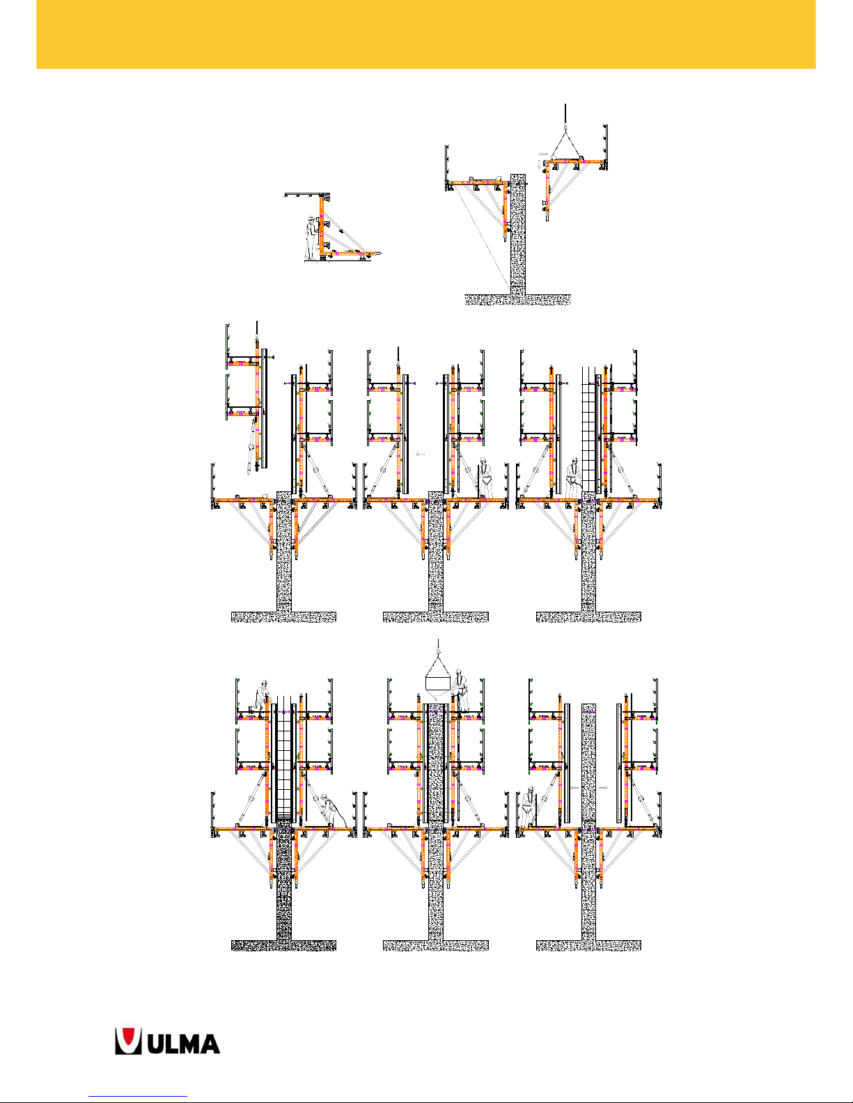
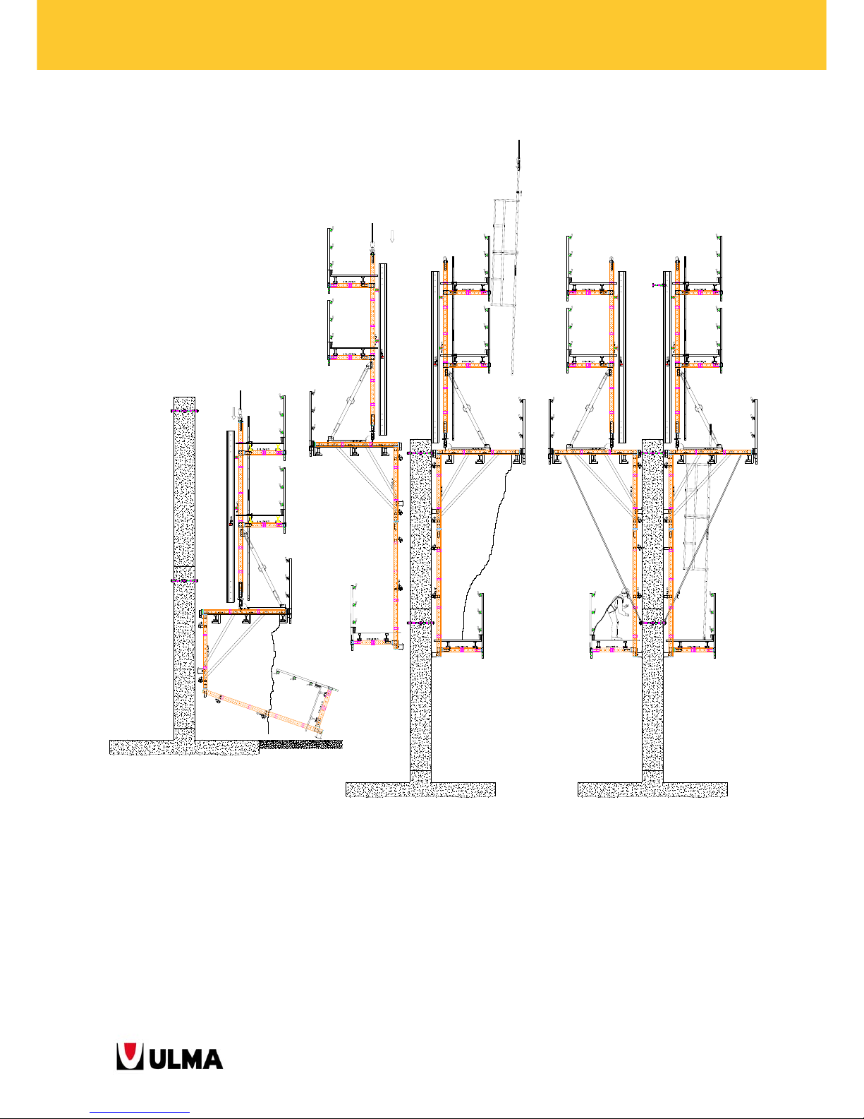
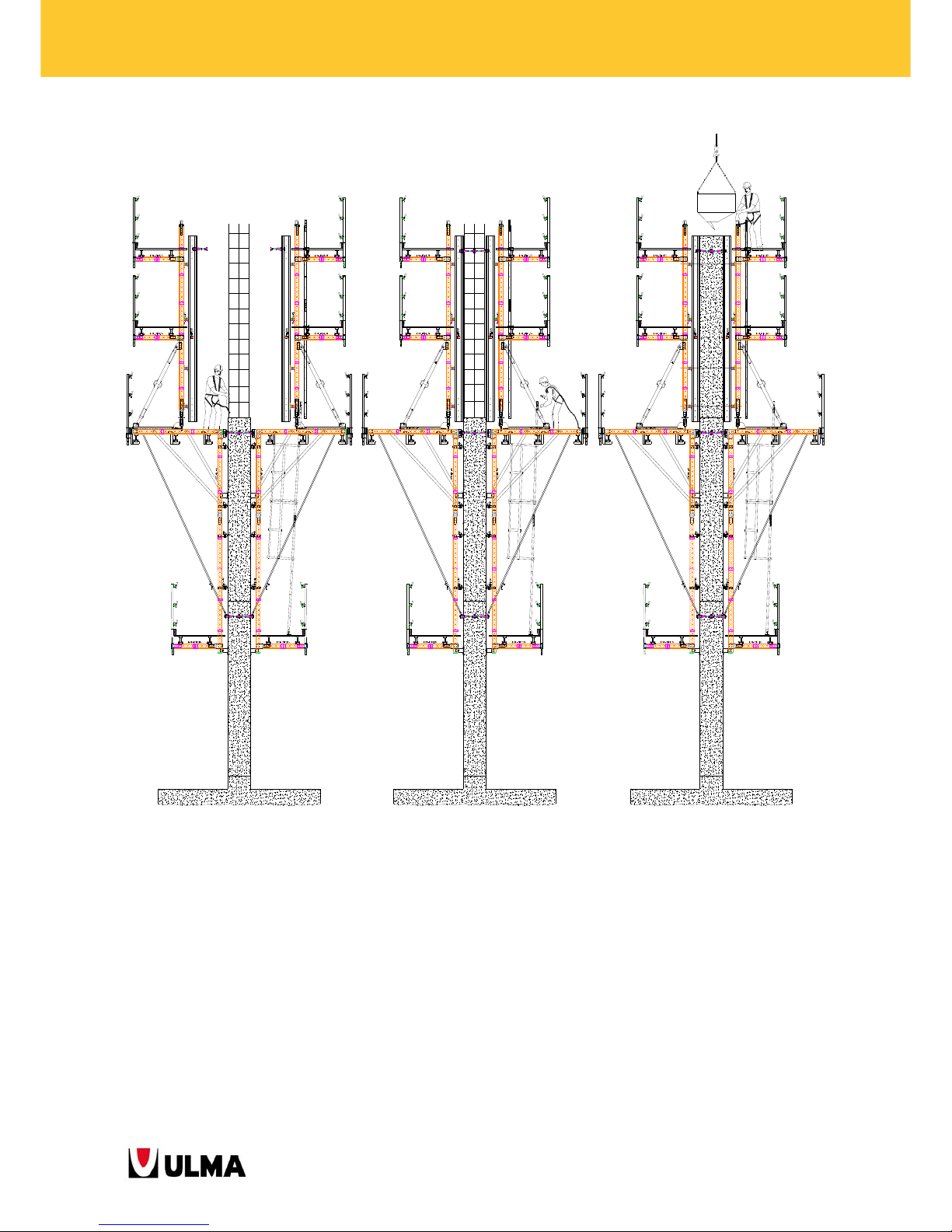
3.2. Instructions for the Climbing Bracket BMK system: Second pouring stage - first
climbing stage
1. Hook the climbing bracket frames to a crane by positioning them vertically and parallel to each other at the
distances indicated in the assembly drawings. Brace them with tubes
48x3 and couplers. Assemble the
working platform and place the Handrail Post onto the climbing bracket.
2. Lift the climbing bracket pair up and support them on the cones which have been previously placed.
3. Lift the panels one by one up onto the main platforms and pin the push-pull props to the main platform
(through the Roll-Back Carriage).
4. Keep the panels from the wall at a distance which allows to work in between them.
5. Clean the panels, apply release agent and place steel reinforcement.
6. Move the panels closer to the concrete wall and plumb them with the push-pull prop. Check the cone positions
by using topography techniques and level the formwork with the Waler Screw TR53X6.
7. Place tie rods and proceed with concrete pouring.
8. Strip the wall by keeping the panels separated from it at an approximate distance of 30 cm to be able to
assemble the climbing rings to the cones from the concrete pouring platform.
9. Hook panel by panel to the crane and lower them to the ground to fasten the cone recovery platform to them
with pins.
10. Formwork panel climbing:
11. Fix the wind bracing cable to the cones of the previous pouring stage and place the cones for the next climbing
stage on the panel. Keep the panels separated from the wall.
12. Clean the panels, apply release agent and place steel reinforcement.
13. Check the cone positions by using topography techniques and level the formwork with the Waler Screw
TR53X6. Move the panels to the wall into concrete pouring position and hit the wedge to block the roll-back
carriage. Place tie rods between the panels.
14. Proceed with concrete pouring.
No workers are allowed on the working platforms during
lifting operations.
Page 34
34
BMK CLIMBING BRACKETS
1
2
3 4 5
6 7 8
Page 35
35
BMK CLIMBING BRACKETS
9
10 11
Page 36
36
BMK CLIMBING BRACKETS
12 13
14
Page 37

37
BMK CLIMBING BRACKETS
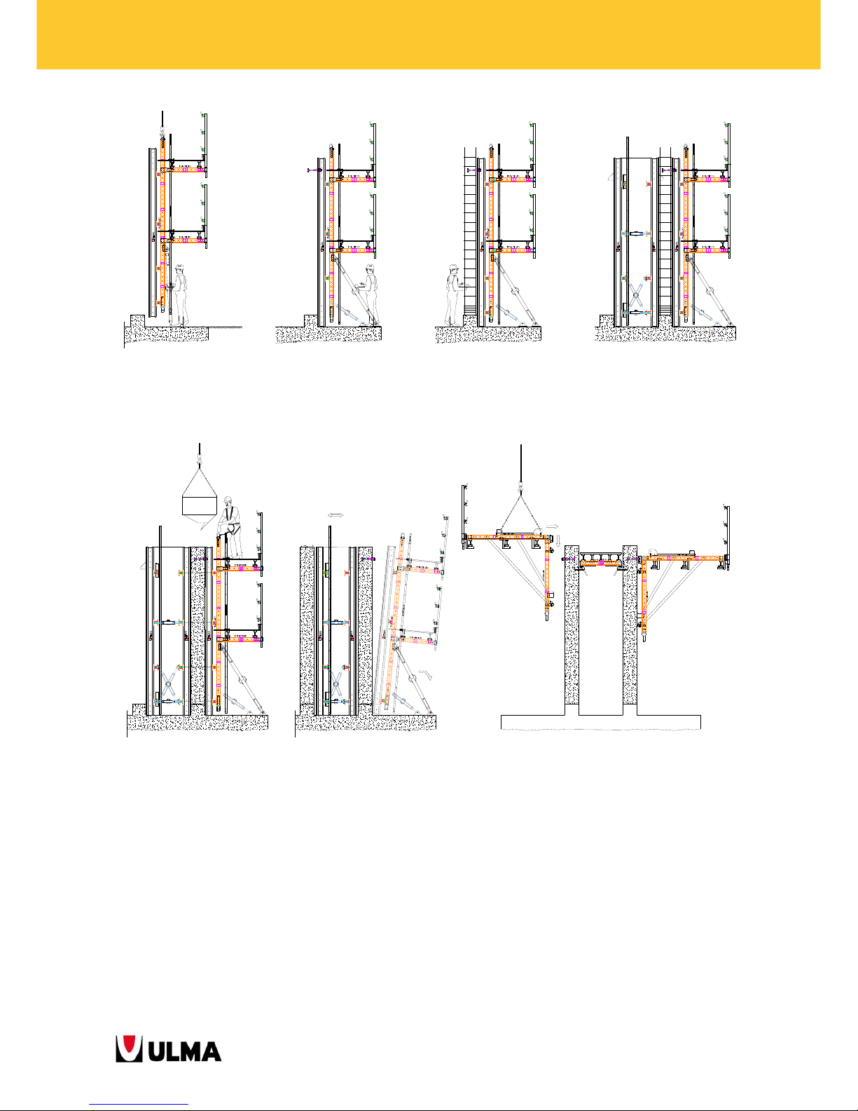
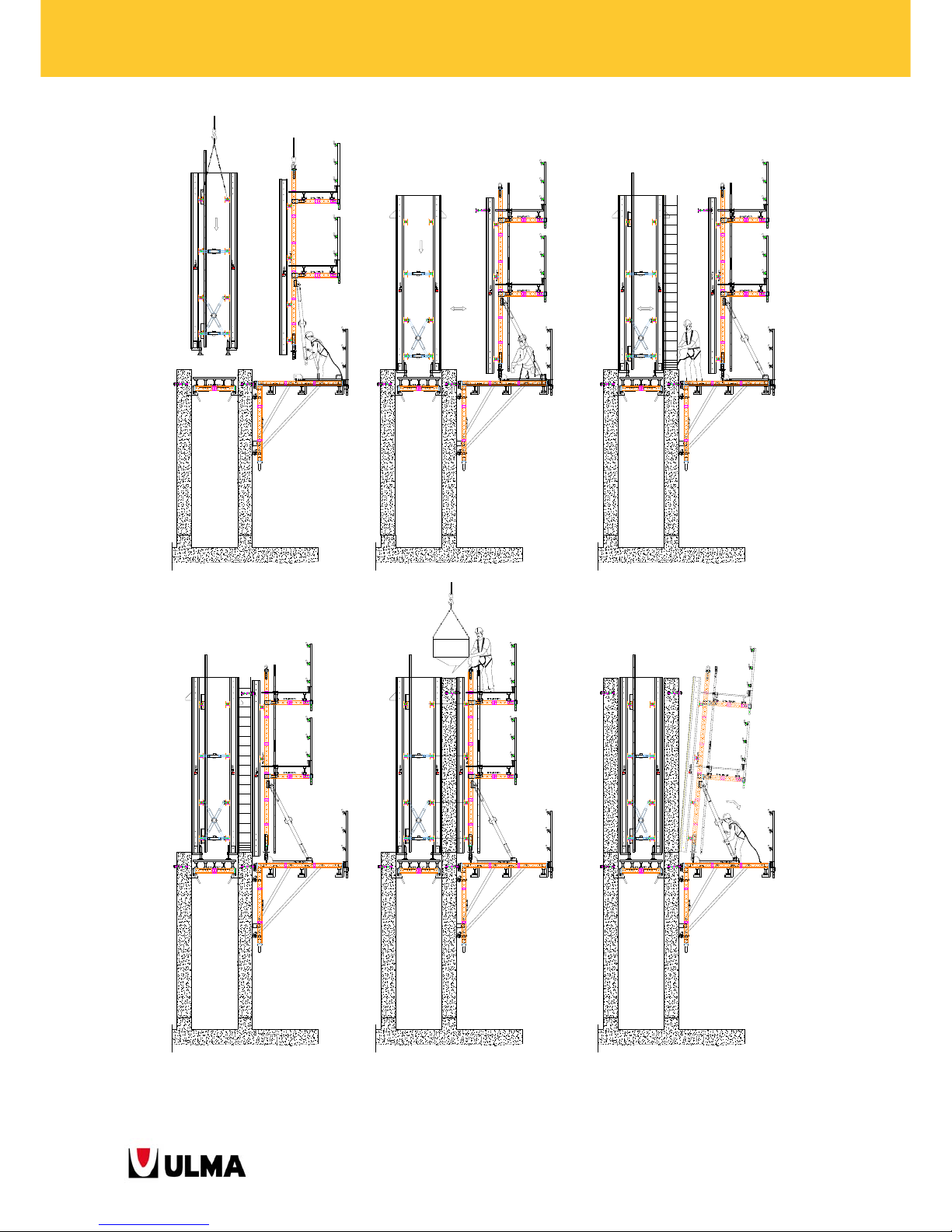
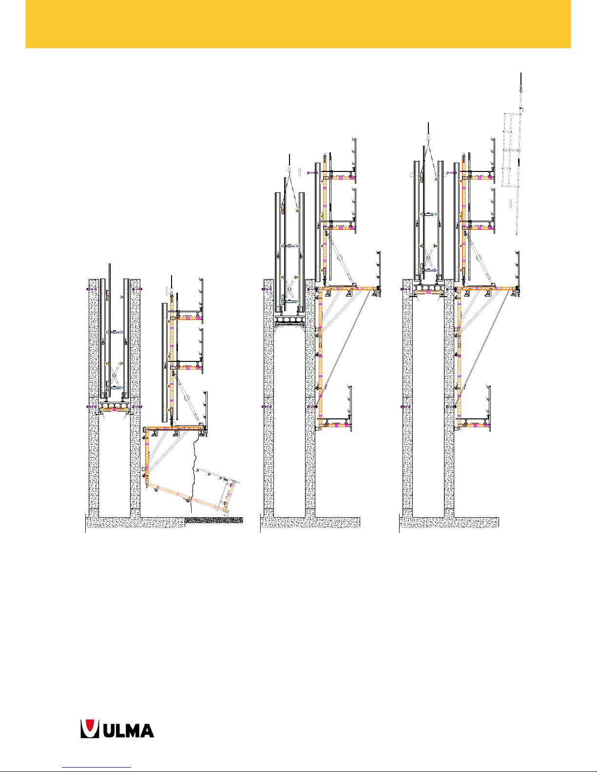
3.3. Instructions for the Climbing Bracket BMK system for the construction of hollow
piers
1. Lift the structure and position it in the indicated location.
2. Place the Base Plates and Push-Pull Props to plumb the formwork panel. Do not let go of the panel with the
crane until having anchored the formwork properly to the ground.
Position the anchor cones to support the climbing system in the next pouring stage according to the
indications in the assembly drawings.
3. Apply release agent and place steel reinforcement.
4. Position the inside formwork without platform and finish placing steel reinforcement. Before though, place the
anchor brackets into the panel for the support of the inside platform. Place the rest of the outside panels.
5. Place tie rods and proceed with concrete pouring.
6. Separate the panels from the wall by adjusting the push-pull props at a distance which allows assembling the
climbing rings to the cones from the concrete pouring platform. Remove the formwork and lower it to the
ground.
7. Set the platform into the pier shaft the way the gravity pawls snap into the box-outs. Lift the climbing brackets
and support them on the cones embedded in the concrete.
8. Assemble the outside panels onto the climbing brackets and the inside formwork onto the platform fixing it
with chains and levelling it.
9. Separate the outside panels from the wall to get sufficient working area to place the cones and anchor
brackets onto the inside formwork panel.
10. Clean the panels, apply release agent and place steel reinforcement.
11. Move the panels to the wall, plumb and level them. Check the cone positions by using topography techniques.
12. Place tie rods and proceed with concrete pouring.
13. Strip the wall by keeping the panels separated from it at an approximate distance of 30 cm to be able to
assemble the climbing rings to the cones from the concrete pouring platform.
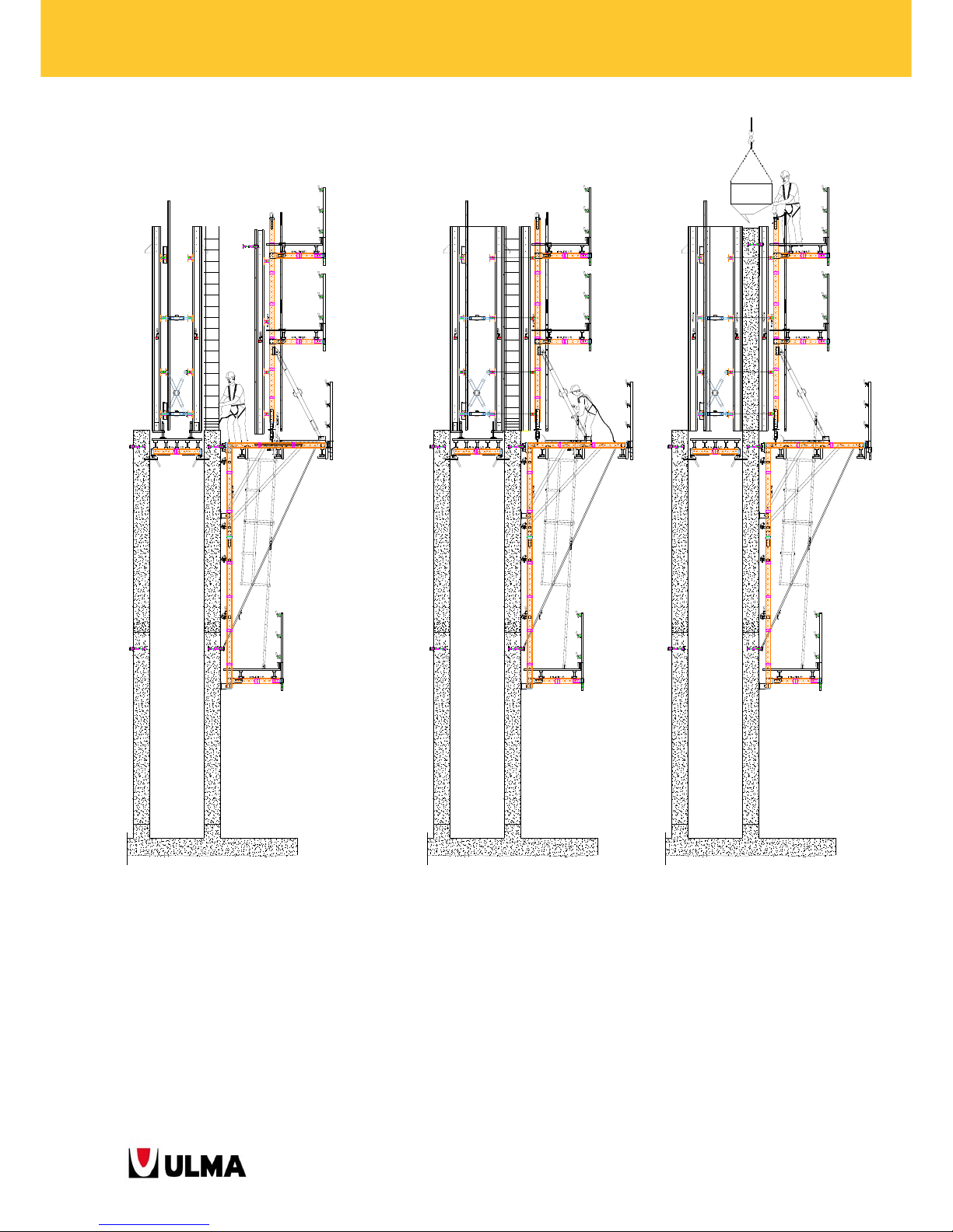
14. Connect the cone recovery platform to the outside panels and move them up to the next climbing stage,
starting with the one with ladders. Once having reached the next climbing stage, tie the wind bracing cable.
Page 38
38
BMK CLIMBING BRACKETS
15. Move the formwork and the inside platform up together to the next climbing stage by letting the gravity pawls
snap into the box-outs.
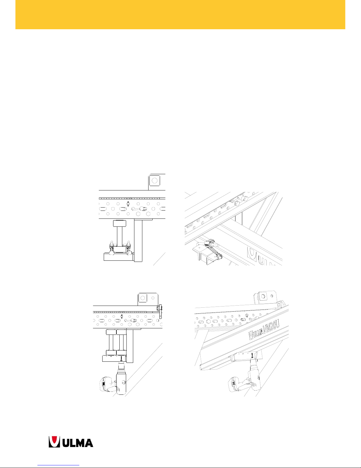
16. Place cones and anchor brackets on the inside and outside formwork. Attach the ladder to the cone recovery
platform.
17. Clean the panels, apply release agent and place steel reinforcement.
18. Move the formwork into concrete pouring position, pass the tie rods through the panels.
19. Proceed with concrete pouring.
No workers are allowed on the working platforms during
lifting operations.
Page 39
39
BMK CLIMBING BRACKETS
5 6
7
1 2 3 4
Page 40
40
BMK CLIMBING BRACKETS
11
12 13
8
9 10
Page 41
41
BMK CLIMBING BRACKETS
14 15 16
Page 42
42
BMK CLIMBING BRACKETS
17 18
19
Page 43
43
BMK CLIMBING BRACKETS
3.4. PLATFORMS ASSEMBLY
As mentioned in the first section "Product description", the climbing brackets BMK allow of the installation of 4
working platforms: main, concrete pouring, vertical waler and cone recovery platform.
3.4.1. Main platform
Subsequently, some main platform assembly variations are shown:
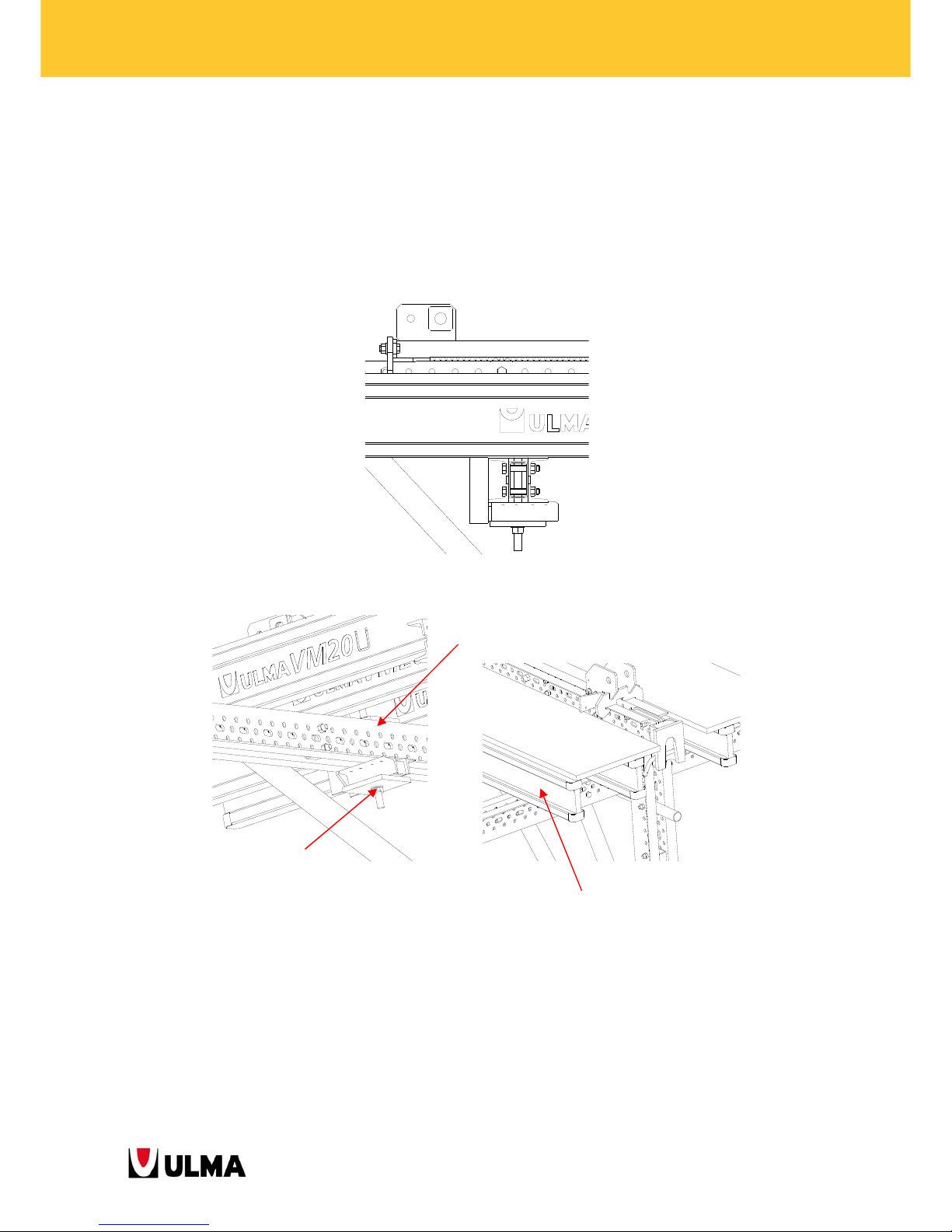
Timber Beams VM20
One or two timber beams per each support can be placed on the climbing brackets depending on the platform
strength required to be obtained.
1 Beam VM20 fastened with Waler-VM20 Clamp 2T
2 Beams VM20 fastened with Screws 6x50 DIN7505-A (9371434)
Page 44
44
BMK CLIMBING BRACKETS
Walers MK-120 (it is also possible to use DU-120 and DU-100):
The corresponding walers are placed lengthwise and the timber beams VM20 perpendicular to them: this
solution for climbing brackets BMK is adopted in cases in which the beams VM20, due to the size of the
platform, are not strong enough to bear the acting loads, mainly in long cantilevers.
3.4.2. Concrete pouring, vertical waler and cone recovery platform
To create these platforms, the timber beams are directly joined to the walers MK.
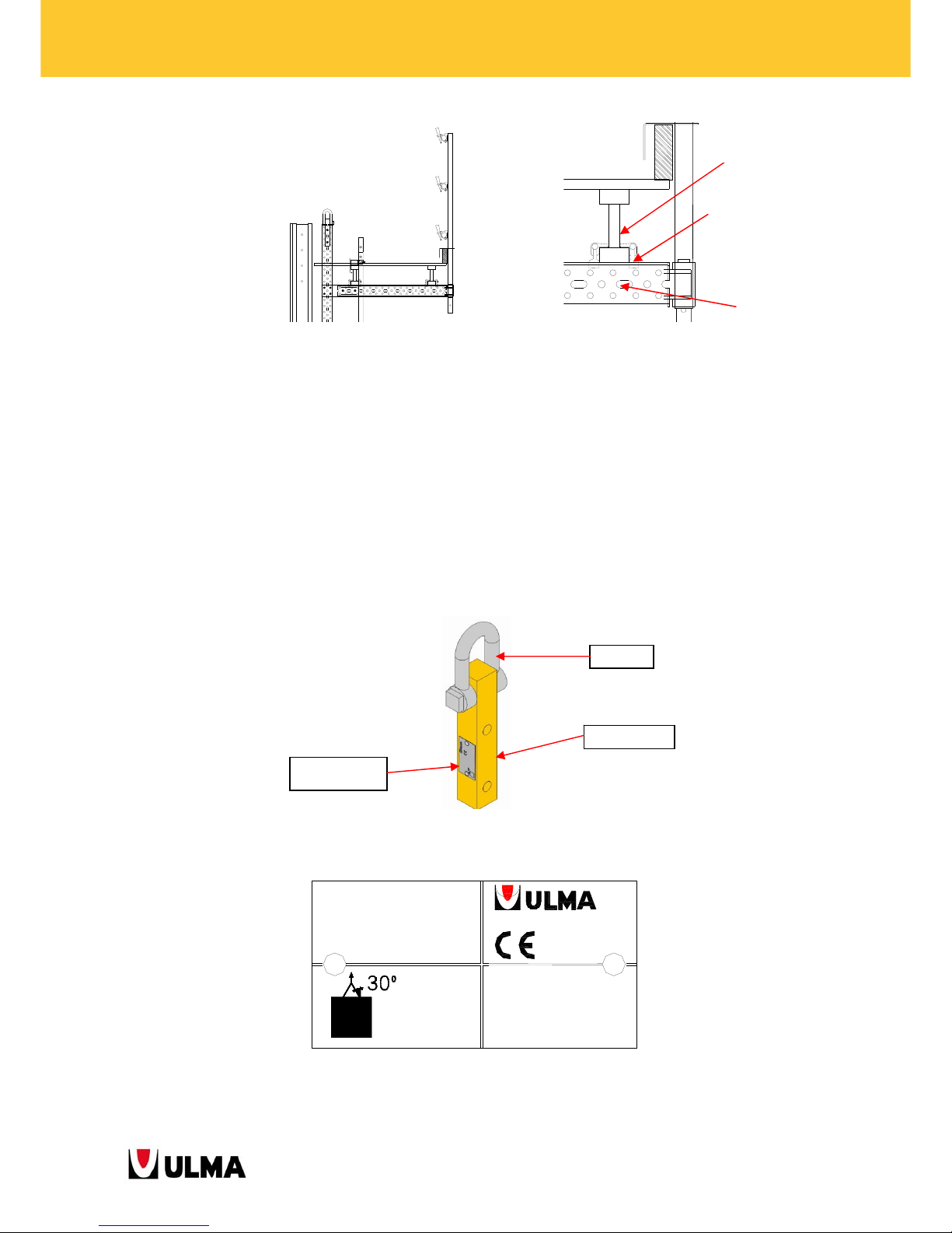
Clamp M20x330 (2P-150x150) (0260001)
Waler MK-120
Timber Beam VM
Page 45
45
BMK CLIMBING BRACKETS
The spacing between the Handrail Posts 1.5 of all platforms is according to standard EN 13374 Temporary edge
protection systems.
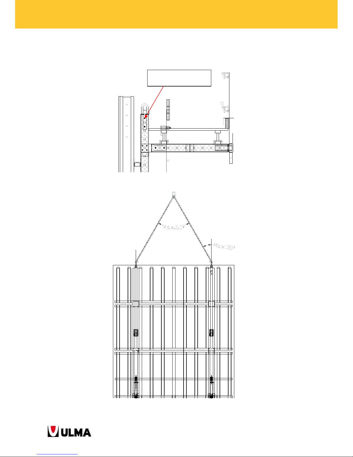
3.5. LIFTING HOOK MK
Item used to lift the structure. It is connected to the top part of the vertical waler (waler MK), that is, each vertical
waler has its own lifting hook attached to it. Each lifting hook is designed to bear a maximum load of 31 kN in
direction of the pull of the sling or 27 kN in vertical pulling direction (moreover the maximum weight of the
structure which is possible to lift is 54 kN or 5400 kg respectively). The static test coefficient used is 1.5.
ID PLATE:
ULMA C y E,S.Coop.
Otadui,3 - Apdo.13
20560 OÑATI (SPAIN)
CARGA MAX. DE USO
MAX. WORKING LOAD
MAX. TRAGFÄHIGKEIT
3100 kg
(6800 lbs)
ANGULO MAX.
DE ESLINGAS
MAX. CHAIN
ANGLE
MAX. NEIGUNGS-
WINKEL
RIOSTRA MK
GRILLETE IZADO MK
LIFTING HOOK MK
FAHRRIEGELKRANÖSE MK
1991360
Chain
Square bar
ID plate
Waler-VM20 Clamp 2T
(1960375)
Waler MK-120
Timber Beam VM
Page 46
46
BMK CLIMBING BRACKETS
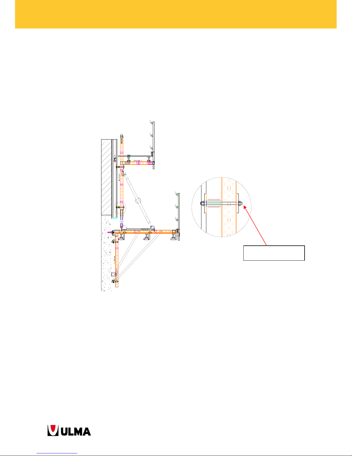
Each lifting hook is fastened to the waler with two pins E20x70.
The crane sling is connected directly to the chain shackle of the hook.
The slings attached to the lifting hook should not exceed the maximum angle of maximum 60º between them.
2 Pins E20x70 (0252070)
2 Cotter Pins R/5 (0250000)
Page 47
47
BMK CLIMBING BRACKETS
3.6. FORMWORK PANEL CONNECTION TO CLIMBING STRUCTURE
The climbing brackets BMK also offer flexibility with regard to the use of different formwork products. The
following panel types can be used.
3.6.1. ENKOFORM V-100 and ENKOFORM VMK panels
The connection between the panel and the vertical walers is obtained with the Clamp M20x330 (2P-150x150)
(0260001).
3.6.2. ORMA panel
When the vertical walers are in direct contact with the panel, the Waler Hook is used attached to the holes of the
panel ribs.
Clamp M20x330 (0260001)
Page 48
48
BMK CLIMBING BRACKETS
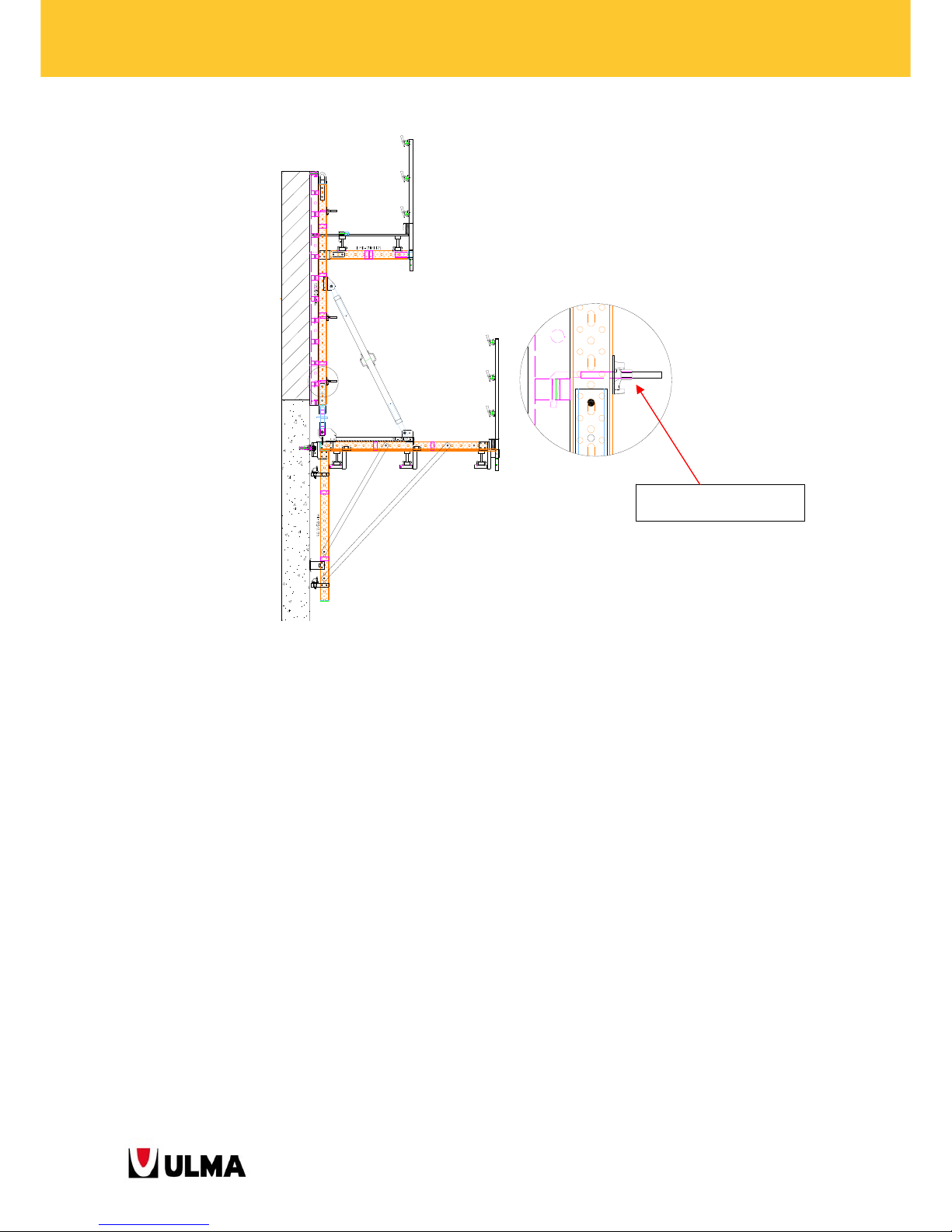
3.6.3. ORMA panel + horizontal waler (MK-120, DU-100 DU-120)
In the case that horizontal walers are placed between the ORMA panel and the climbing structure, the connection
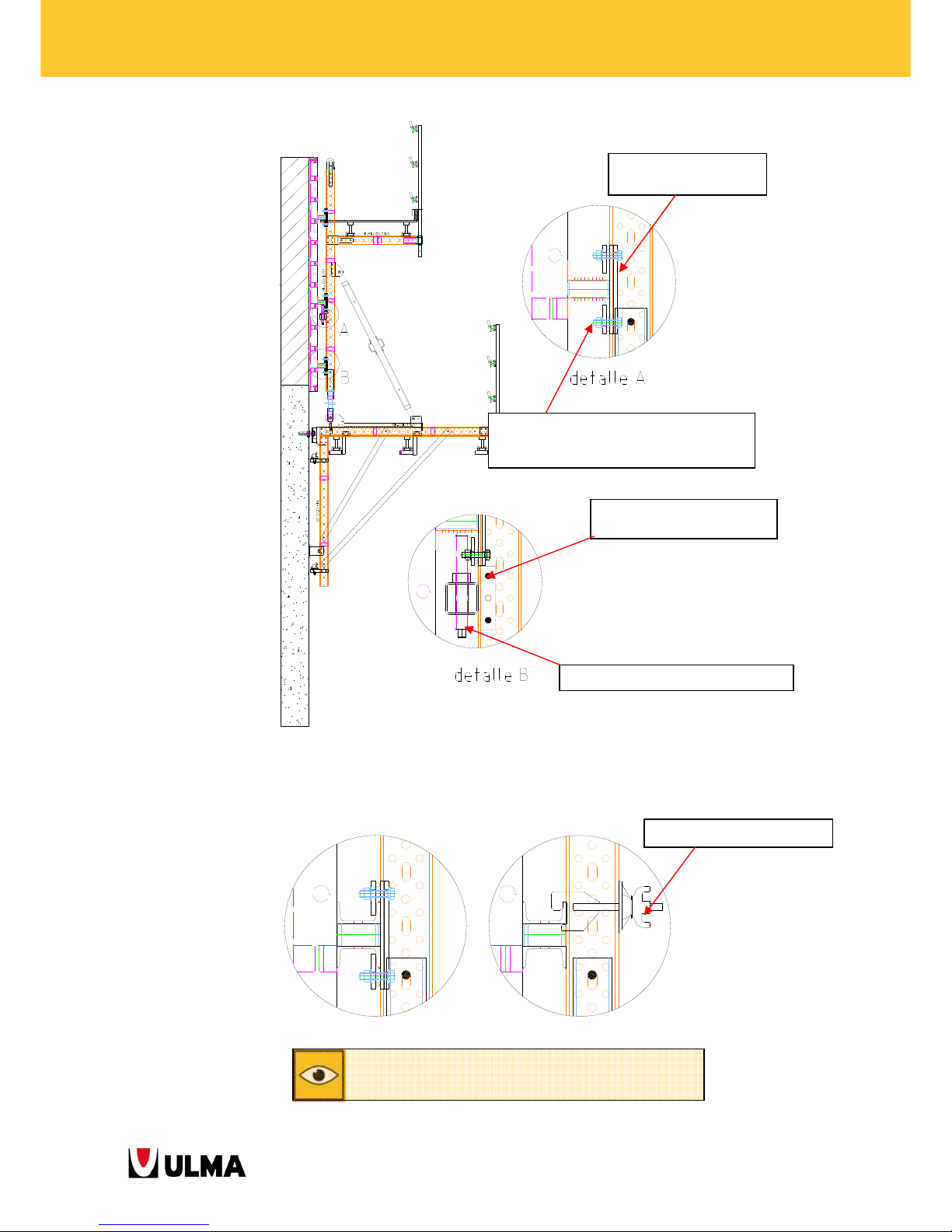
with the vertical walers is obtained with Plate Clamps DU-DU (4 per each connection) fastened with bolts between
each other and Adjustment Jacks MK-120.
Waler Hook (1900448)
Page 49
49
BMK CLIMBING BRACKETS
If a waler DU-100 is used as horizontal waler, the Waler Fixing Hook (0333004) can also be used for the
connection between the vertical and the horizontal waler.
Waler Fixing Hook (0333004)
The Waler Fixing Hook can ONLY be used with the horizontal waler
DU-100
,
NOT with the DU-120 or MK-120.
2 Bolts M16x90 (0241690)
2 Nuts M16 (0241600)
Adjustment Jack MK-120 (1991567)
4 Plate Clamps DU-DU
(0919259)
4 Bolts M16x70 DIN933-8.8 (0241670)
4 Nuts M16 DIN934-8 (0241600)
8 Washers A16 DIN125 (0241600)
Page 50
50
BMK CLIMBING BRACKETS
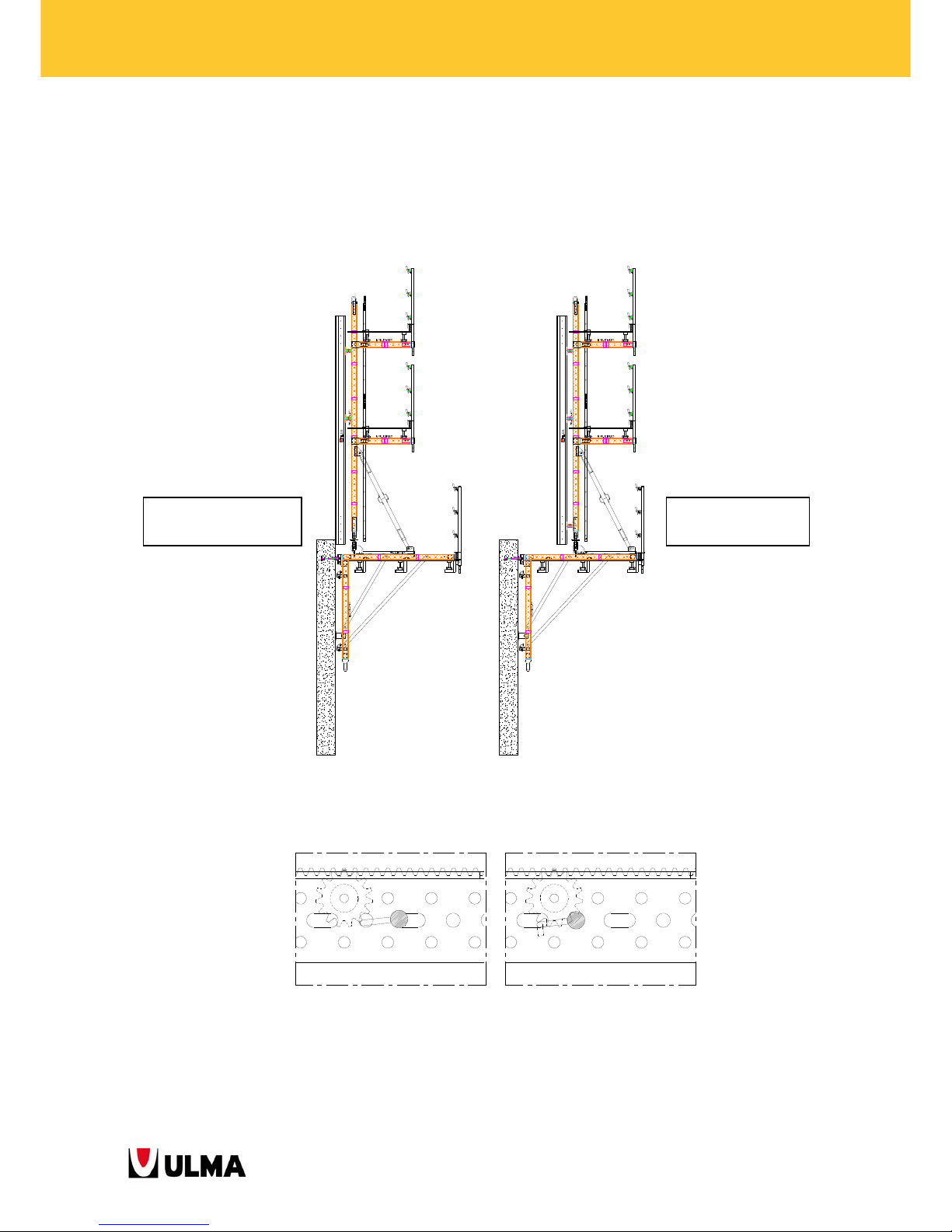
3.7. STRIPPING SYSTEM
3.7.1. Roll-Back Carriage
If a working area is required between the wall and the formwork, the Climbing Brackets BMK-240 (1991424)
The stripping process comprises the following steps:
1. Place the Gear Locker MK (1991510) in unblocked position in case it is set to blocked.
Unblocked position Blocked position
CONCRETE POURING
POSITION
STRIPPING
POSITION
Page 51
51
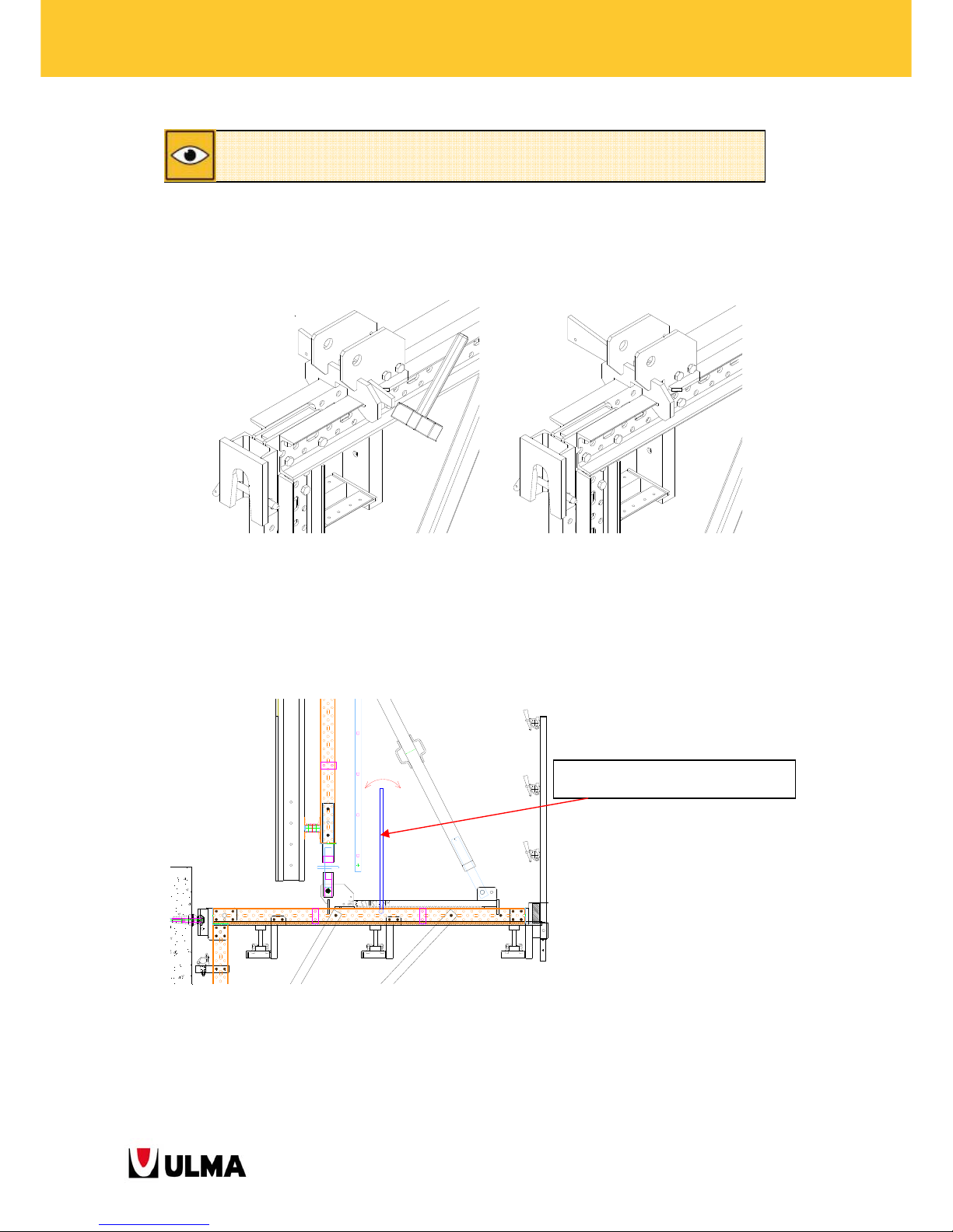
BMK CLIMBING BRACKETS
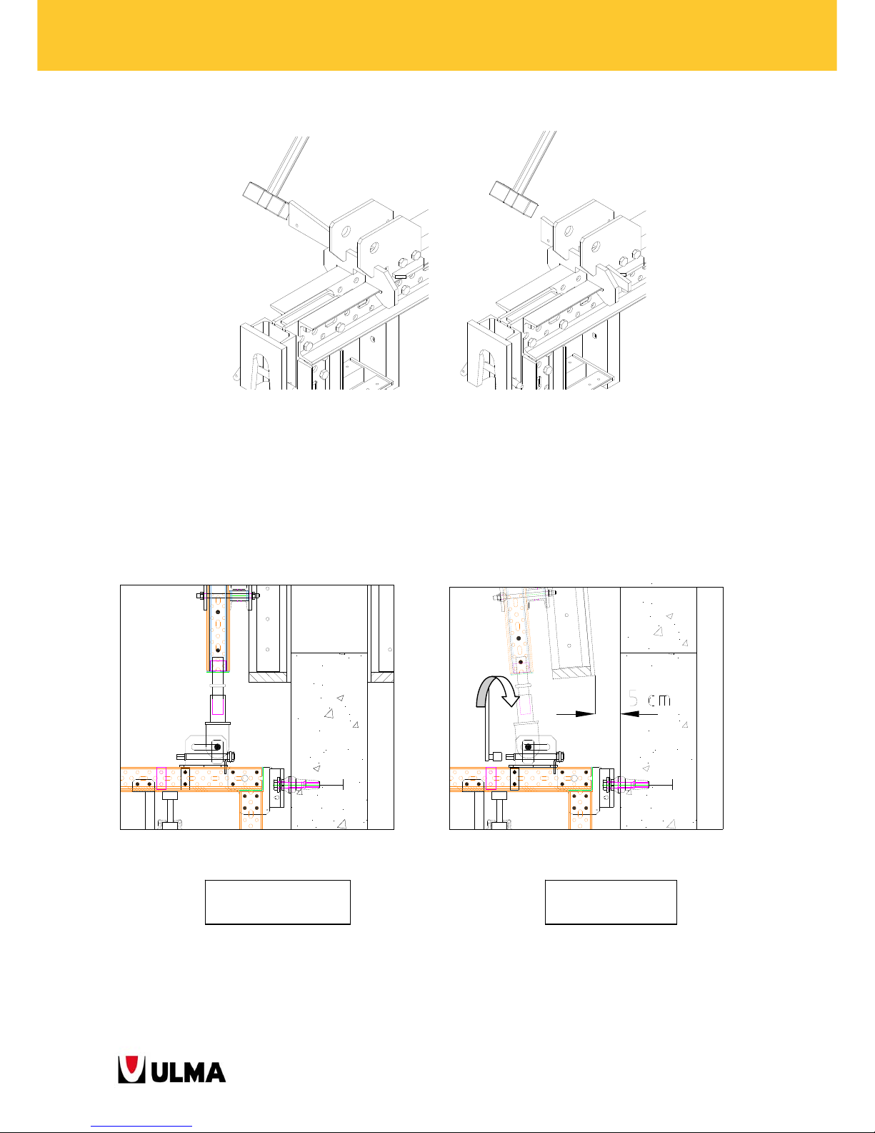
2. Hit the wedge with a hammer to unblock the Roll-Back Carriage.
Blocked Roll-Back Carriage Unblocked Roll-Back Carriage
3. Use a ratchet wrench ¾ to turn the head of the axis thus moving the carriage to its subsequent position.
For out-of-service cases and whenever moving the climbing bracket with crane,
always set the Gear Locker MK to the blocked position.
Telescopic Ratchet Wrench ¾ (9700225)
Socket ¾ width across flats 24
(
9700226
)
Page 52
52
BMK CLIMBING BRACKETS
4. Hit the wedge with a hammer to block the Roll-Back Carriage.
Unblocked Roll-Back Carriage Blocked Roll-Back Carriage
3.7.2. Tilt-Back MK-120
The formwork is joined to the main platform through the Tilt-Back MK-120(1991467). The panels can be separated
from the poured concrete wall to a distance of about 5 cm.
For stripping the screw jack (24 mm width across flats) is adjusted which causes the mobile nut to slide along the
slot. The Pin D32 inserted into the mobile nut and connected to the vertical waler drags the vertical waler with the
attached formwork away from the wall.
CONCRETE POURING
POSITION
STRIPPING
POSITION
Page 53
53
BMK CLIMBING BRACKETS
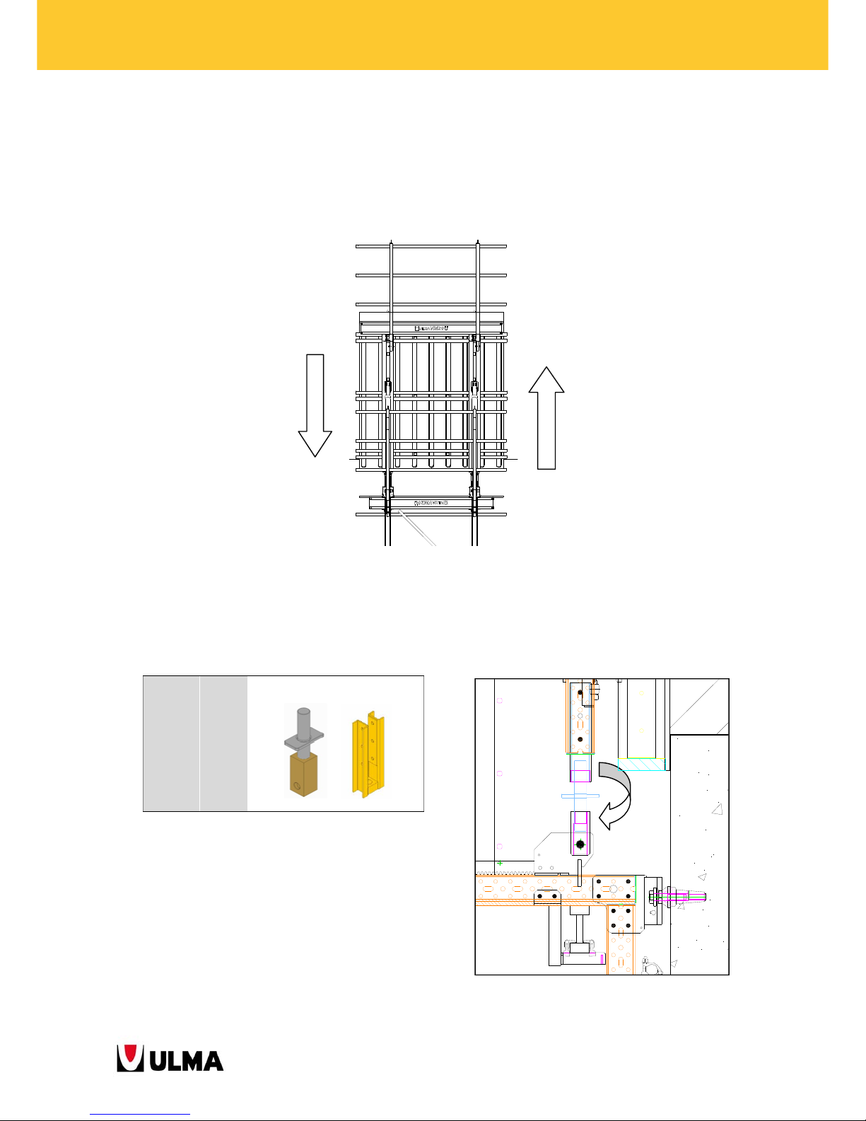
3.8. HEIGHT ADJUSTMENT
It is often required to adjust the formwork height to correctly overlap the panel with the previous pouring stage.
For such adjustment the Waler Screw TR53x6 (0302020) is used.
3.8.1. Roll-Back Carriage MK
The height adjustment is obtained by turning the waler screw in one or the other direction. The adjustment range is
approximately about some 100 mm.
0302020
1991570
10.8
13,5
WALER SCREW TR53X6
WALER MK-120 SCREW BRACKET
Page 54
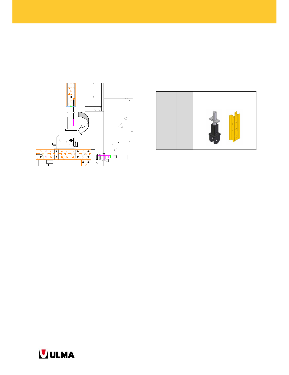
54
BMK CLIMBING BRACKETS
3.8.2. Tilt-Back MK-120
The height adjustment is obtained by turning the waler screw in one or the other direction. The adjustment range is
approximately about some 120 mm.
1991517
1991570
15.7
13,5
CONNECTOR MK SCREW WALER BASE
WALER MK-120 SCREW BRACKET
Page 55
55
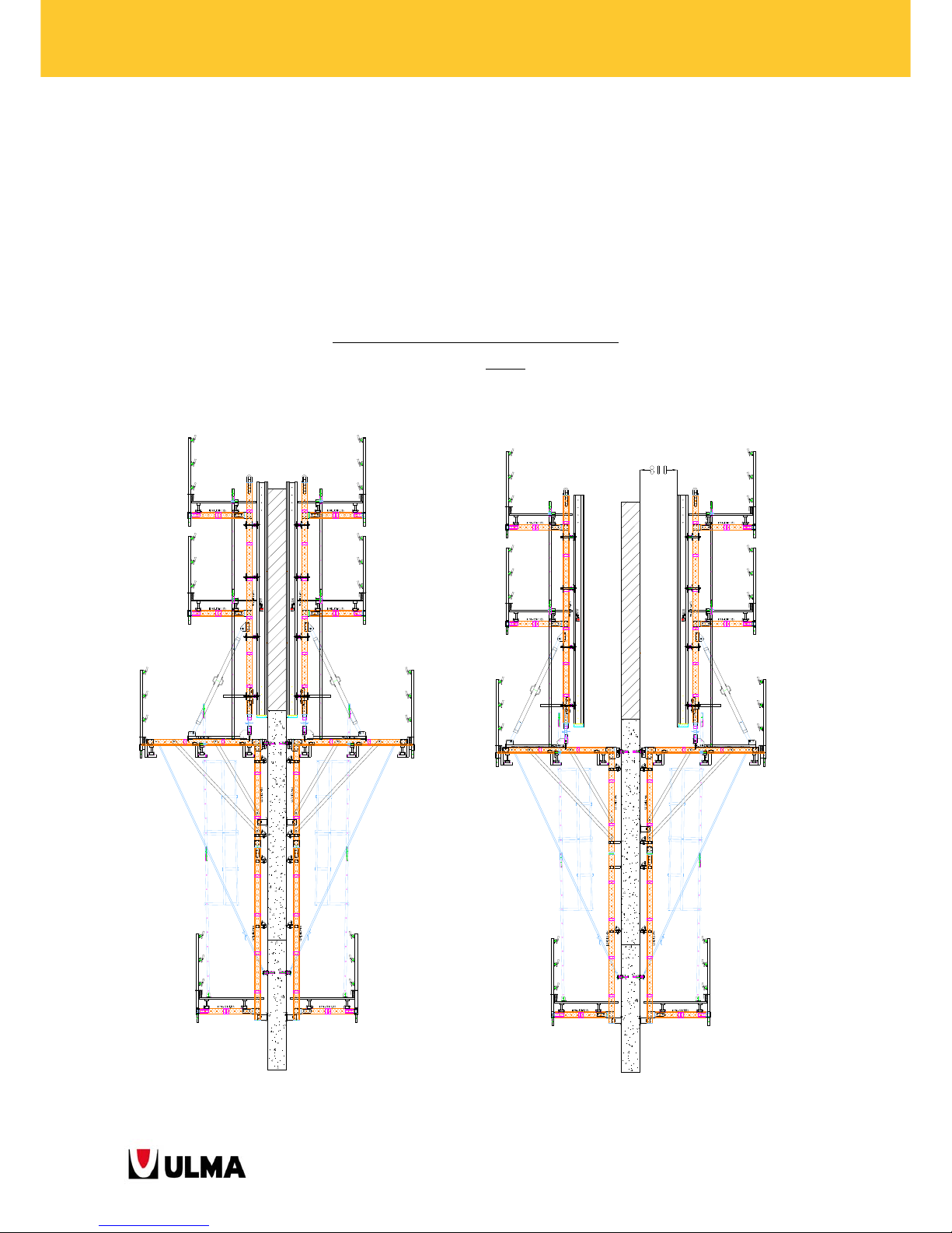
BMK CLIMBING BRACKETS
4. SOLUTIONS
Subsequently, the most common solutions with the climbing brackets BMK are described.
4.1. STRAIGHT WALLS
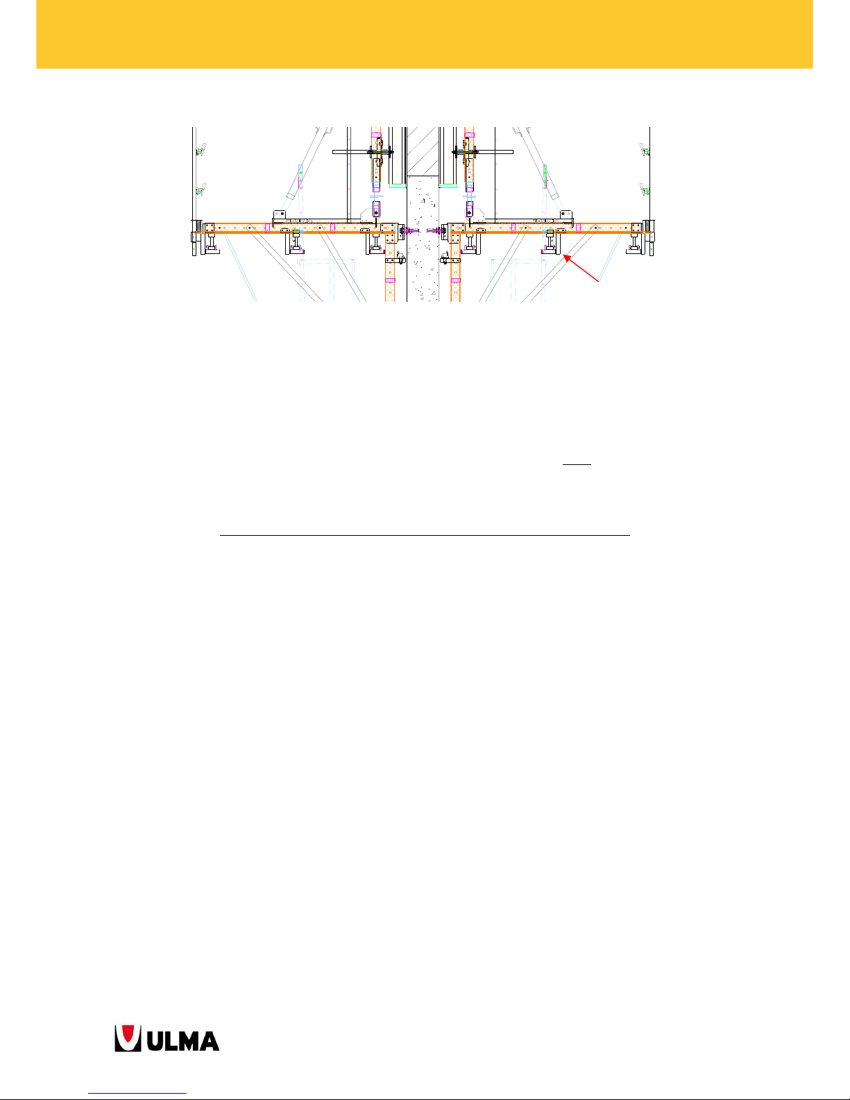
4.1.1. Straight walls with Roll-Back Carriage at both sides of the wall
In this configuration, the formwork of both wall sides is moved back to the maximum distance to ease steel
reinforcement works.
CLIMBING BRACKET BMK-240 AT BOTH SIDES
The distance between wall and formwork is approximately 80 cm
but the exact distance depends on the formwork
type used (see section 2.2.1).
CONCRETE POURING POSITION STRIPPING POSITION
Page 56
56
BMK CLIMBING BRACKETS
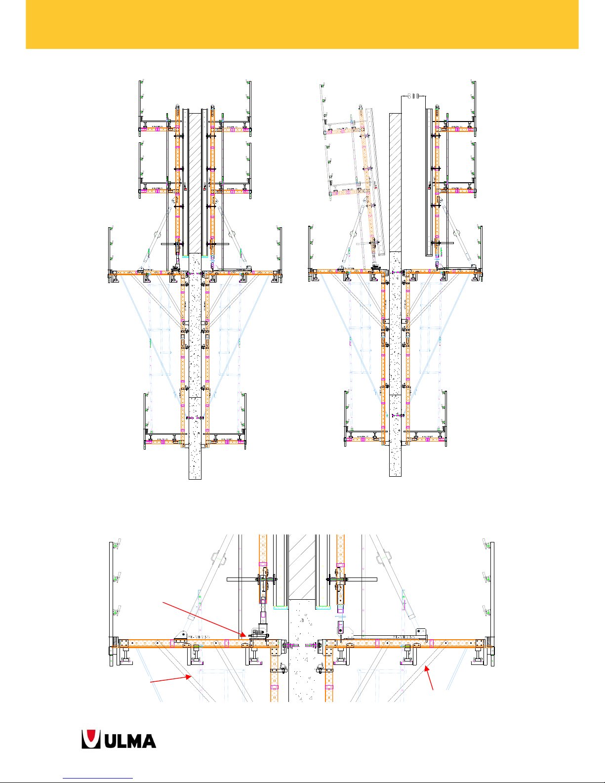
4.1.2. Straight walls with Roll-Back Carriage at one side and Tilt_Back system at the other side of the
wall
In these configurations only the formwork of one side of the wall is stripped with roll-back carriages because the
steel reinforcement works can be done from this side. It is an easier and cost-saving alternative. At the side of the
tilt-back system, the formwork can be separated from the wall by approximately 5 cm
and tilted by means of the
push-pull prop.
CLIMBING BRACKET BMK-240 and BMK-240 FRAME with Tilt-Back system
In this configuration, the same BMK-240 Frames are used but at one side the frame is equipped with roll-back
carriages and at the other it is equipped with the tilt-back system.
Climbing Bracket BMK-240
Page 57
57
BMK CLIMBING BRACKETS
CONCRETE POURING POSITION STRIPPING POSITION
Tilt-Back MK-120
BMK-240 Frame
Climbing Bracket
-
Page 58
58
BMK CLIMBING BRACKETS
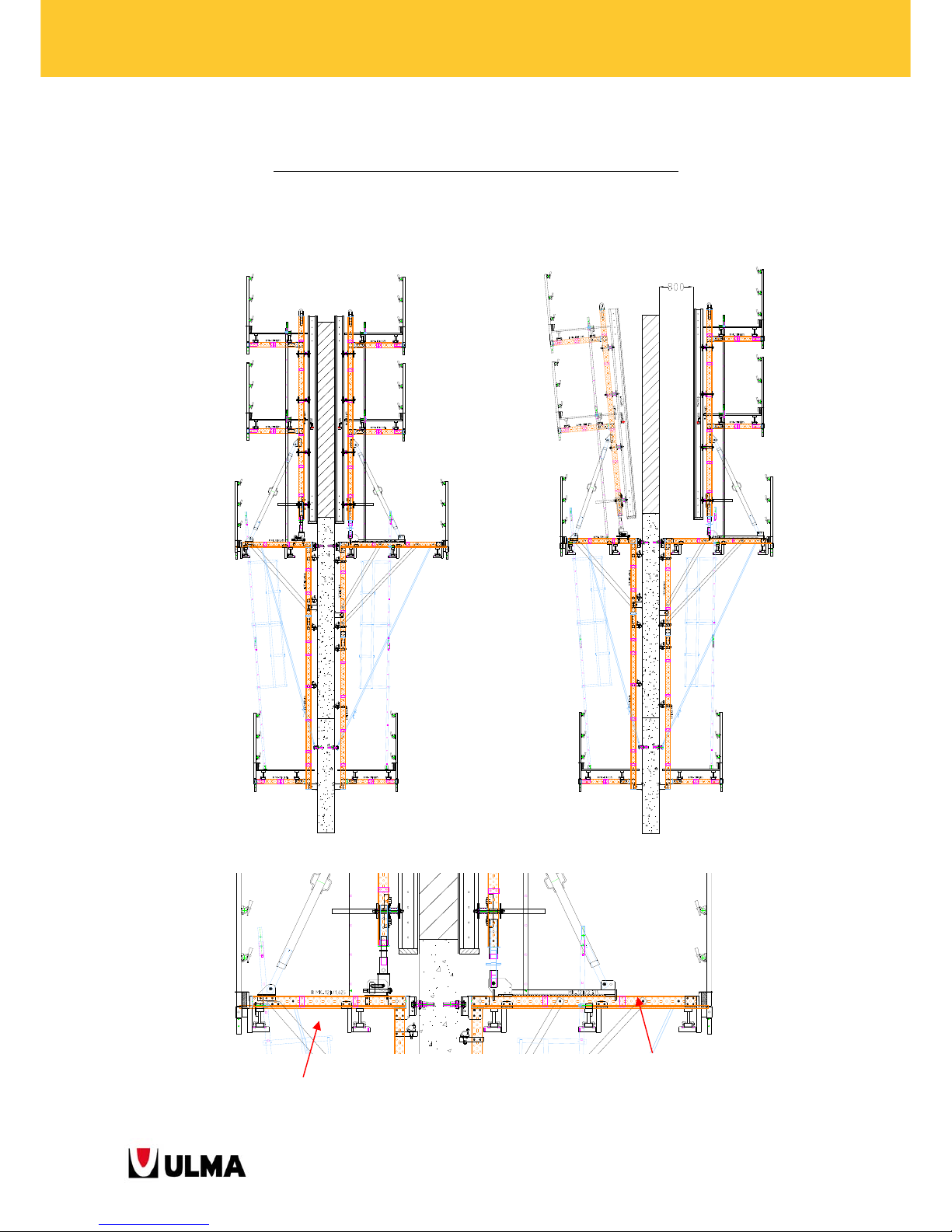
CLIMBING BRACKET BMK-240 and CLIMBING BRACKET BMK-170
In this case, additionally to the installation of the tilt-back system at one side, also the size of the working platform
of this side is reduced by using the Climbing Bracket BMK-170. This configuration is even simpler and cheaper than
the previous ones.
Climbing Bracket
BMK-170
Climbing Bracket
BMK-240
Page 59
59
BMK CLIMBING BRACKETS
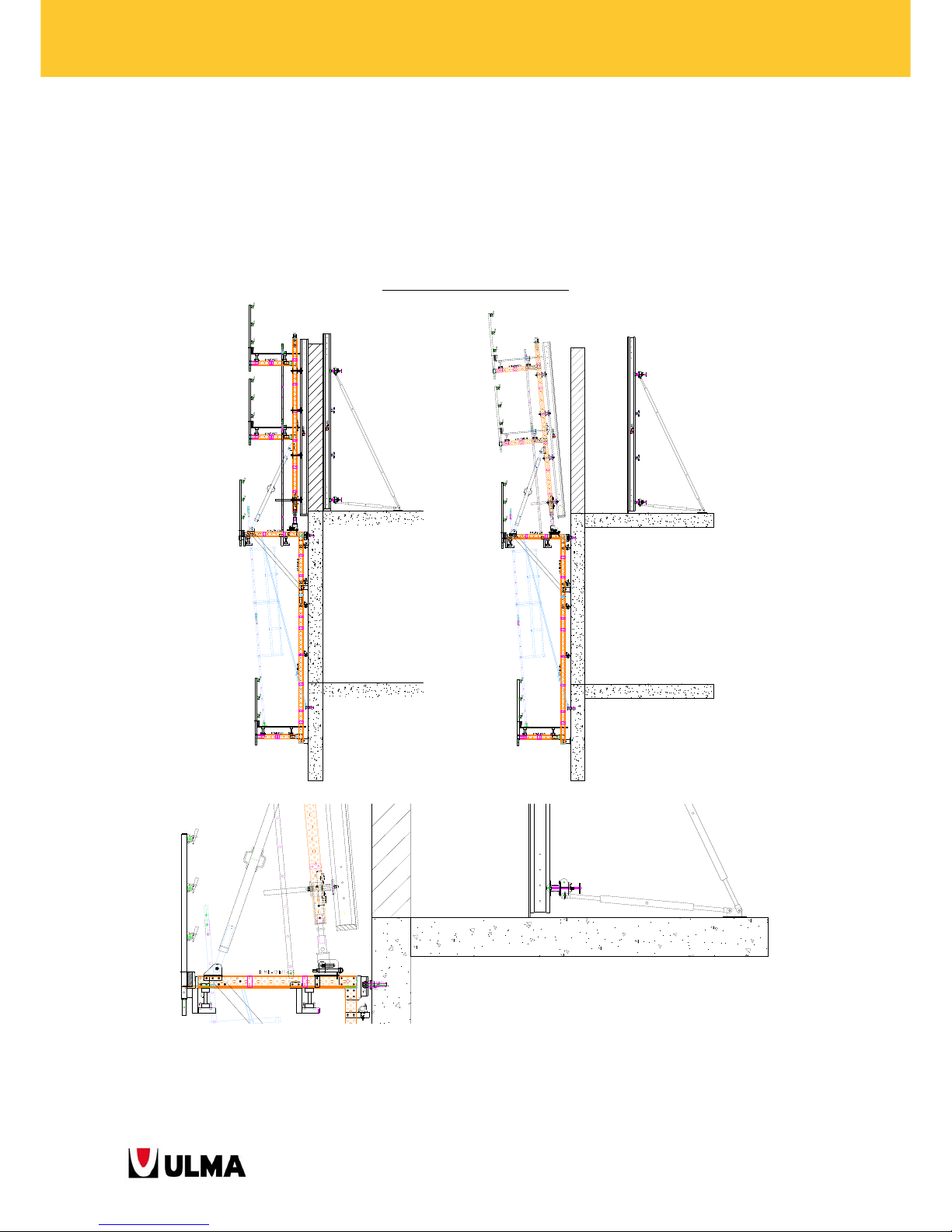
Straight perimeter walls with inside slab
In this configuration, the climbing bracket is only used at the outside of the wall because the inside formwork
supports directly on the slab already built. Therefore, a working area between wall and outside formwork is not
necessary. Instead the inside formwork is removed and the steel reinforcement works are carried out from the
inside. For these cases, the adequate configuration is with the Climbing Bracket BMK-170.
CLIMBING BRACKET BMK-170
Page 60
60
BMK CLIMBING BRACKETS
4.2. INCLINED WALLS
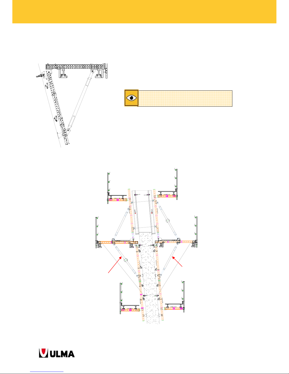
For ±15º inclined wall solutions, the Hinged BMK-240 Bracket (1991465) is used.
In these cases should be used beam formworks “ENKOFORM”.
For the cases that the angle between the horizontal and vertical beam is greater than 90º, the Push-Pull Prop
TR63x6 2.04-2.2 (0333014) is used instead of Push-Pull Prop TR63x6 1.52-2.2 (1991514).
0333014
1991514
Máximum angle on vertical ±15º
Page 61
61
BMK CLIMBING BRACKETS
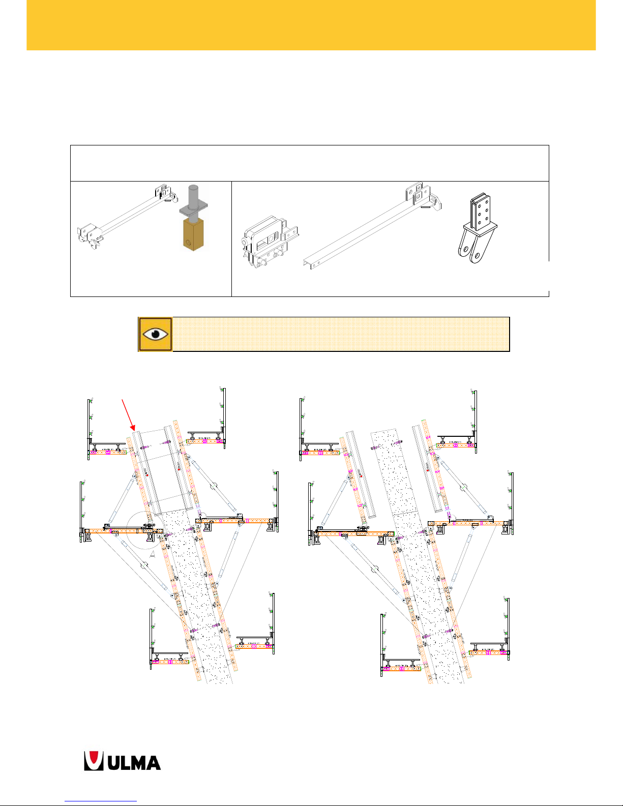
At the side of the overhang and slopes bigger than 5º the Roll Back Carriage BMK (1991444) and the Waler screw
TR53x6 (0302020) should be replaced by the Inclined Tilt-Back MK-120 (1991463) the Assembly Rack MK-120
(1991450) and the Single Side Connector MK-120 (1991593).
OVERHANGING FORMWORK FACE
CONCRETE POURING POSITION STRIPPING POSITION
For inclined wall solutions, specific calculations must be made for each application.
Roll-Back Carriage
MK
(1991444)
Inclined Tilt-Back MK-120
(
1991463
)
Assembly Rack MK-120
(1991450)
Single Sided
Connector MK-120
(1991593)
Overhang
formwork
Waler screw TR53X6
(0302020)
Page 62
62
BMK CLIMBING BRACKETS
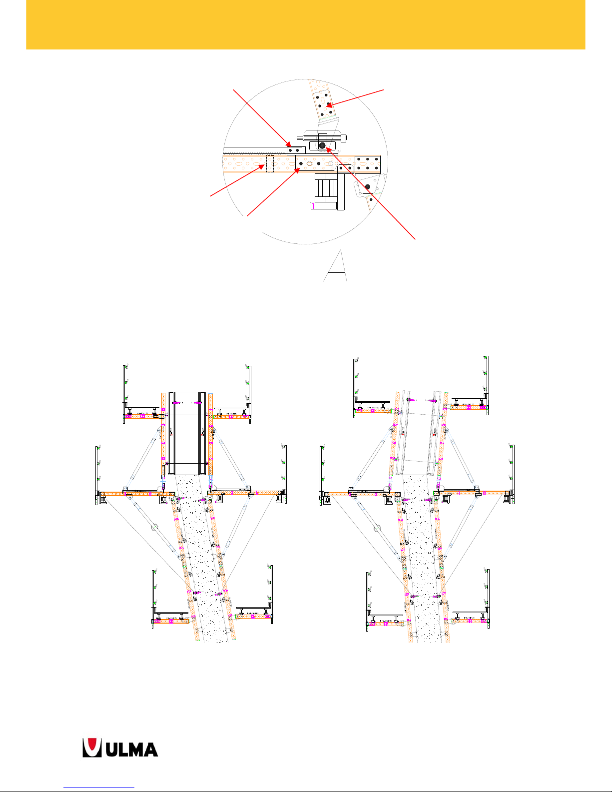
The system also offers solutions for the following geometries:
Walls with transitions from inclined to straight Walls with changing inclination direction
2 Pins E20x70 (0252070)
2 Cotter Pins R
/5 (
0250000
)
REMOVE SPACER FROM
THE MK WALER
6 Bolts M16x90 (0241690)
6 LockNuts M16 (0241608)
1 Pin w/head D34x135 (0253413)
1 Cotter Pins R/5 (0250000)
2 Bolts M16x140 (0241614)
2 Nuts M16 (0241600)
2 Washers A16 (0241601)
Page 63
63
BMK CLIMBING BRACKETS
4.3. CURVED AND POLYGONAL WALLS
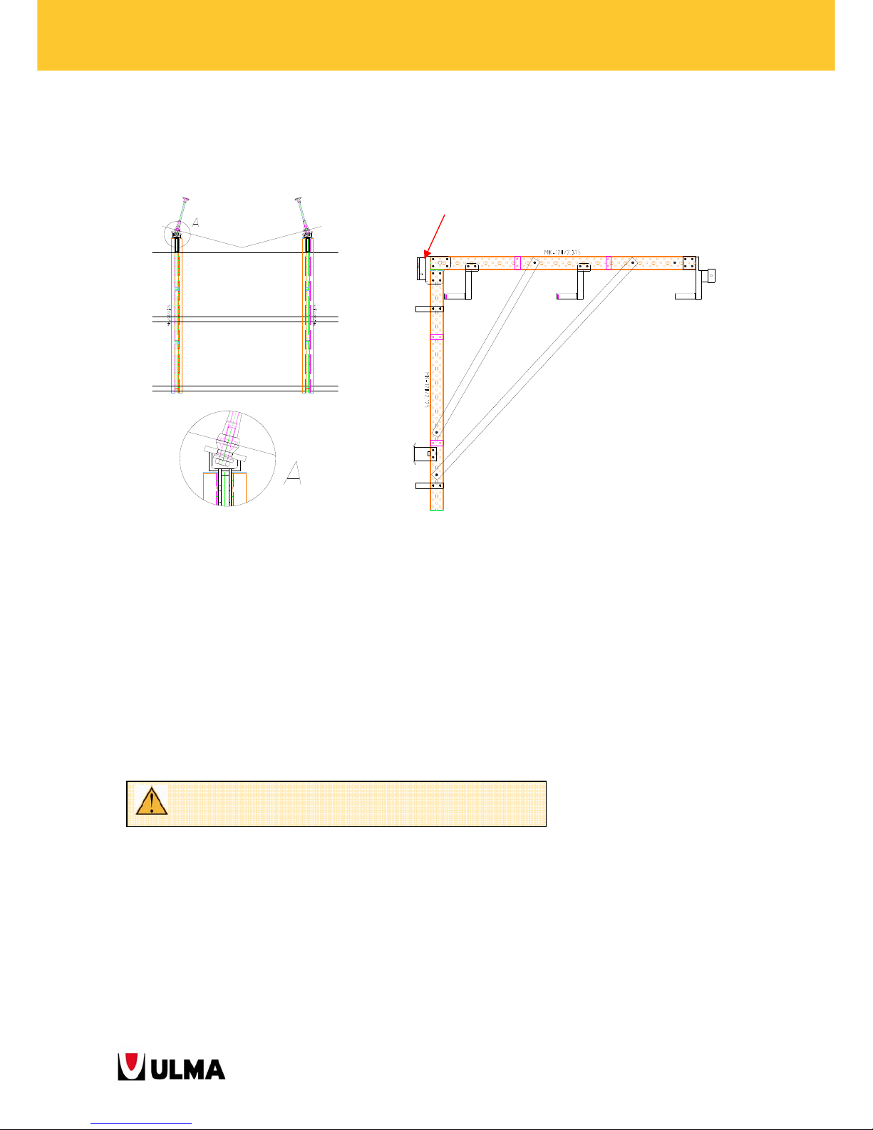
For solutions of curved and polygonal walls, the Fixed Head (1991410) is replaced by a special head with a
particular angle for each application.
4.4. ANCHORAGE SOLUTIONS
The anchors are the tie members of the climbing bracket to the wall.
It is of utmost importance to embed the anchors into the concrete as indicated in the assembly drawings in order
to correctly transmit the loads from the structure to the concrete. The correct transmission of the anchor reactions
to the concrete is responsibility of the customer. Only genuine components of ULMA may be used.
Depending on the reactions in the anchors, DW20 or DW15 anchorages are used.
Change of Fixed Head (1991410) by
special head for inclined wall
Do not weld anchorage components because of the risk of fractures.
Page 64
64
BMK CLIMBING BRACKETS
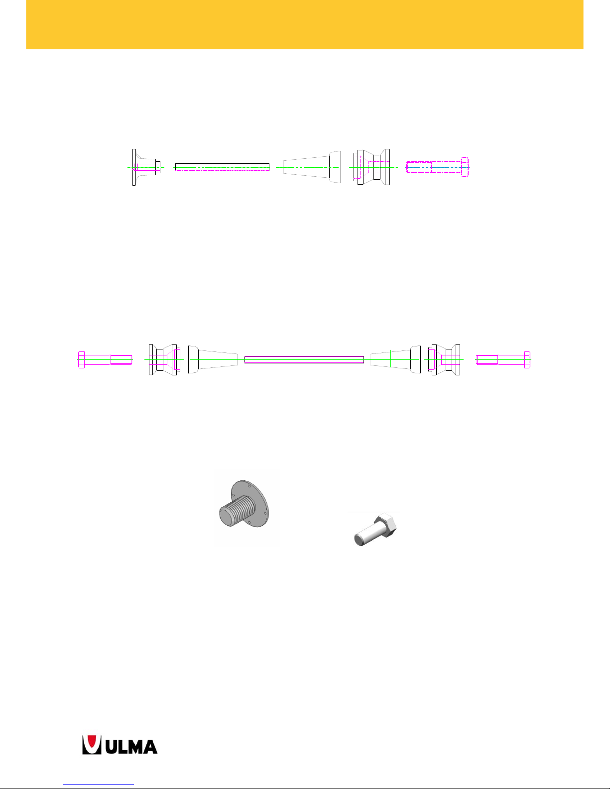
Anchorage DW 15
The set assembled of fixed anchor, tie rod DW15 and cone DW15/M24 remains embedded in the concrete and the
climbing ring DW15-NT20 is fastened to the set with the bolt M24x120. There is also the possibility to place two
cones face-to-face without the requirement of the fixed anchor.
To position the cone on the formwork panel (without using a bolt), the Cone Positioner M24 is used, and the
Positioner Spanner for its removal.
Cone Positioner M24 Positioner Spanner
(1900210) (1900211)
Special care has to be taken when tightening the bolts M24x120 as well as the tie rods DW15 and the fixed
anchors to ensure the effective transmission of loads from the structure to the concrete.
Fixed Anchor
DW15
(
0230005)
Tie Rod DW15
Cone DW15/M24
(
1901080
)
Climbing Ring
DW15-NT20
Bolt M24x120
(
9053013)
Tie Rod DW15
Cone DW15/M24 (1901080)
Climbing Ring DW15-NT20
(1901089)
Bolt M24x120 (9053013)
Page 65
65
BMK CLIMBING BRACKETS
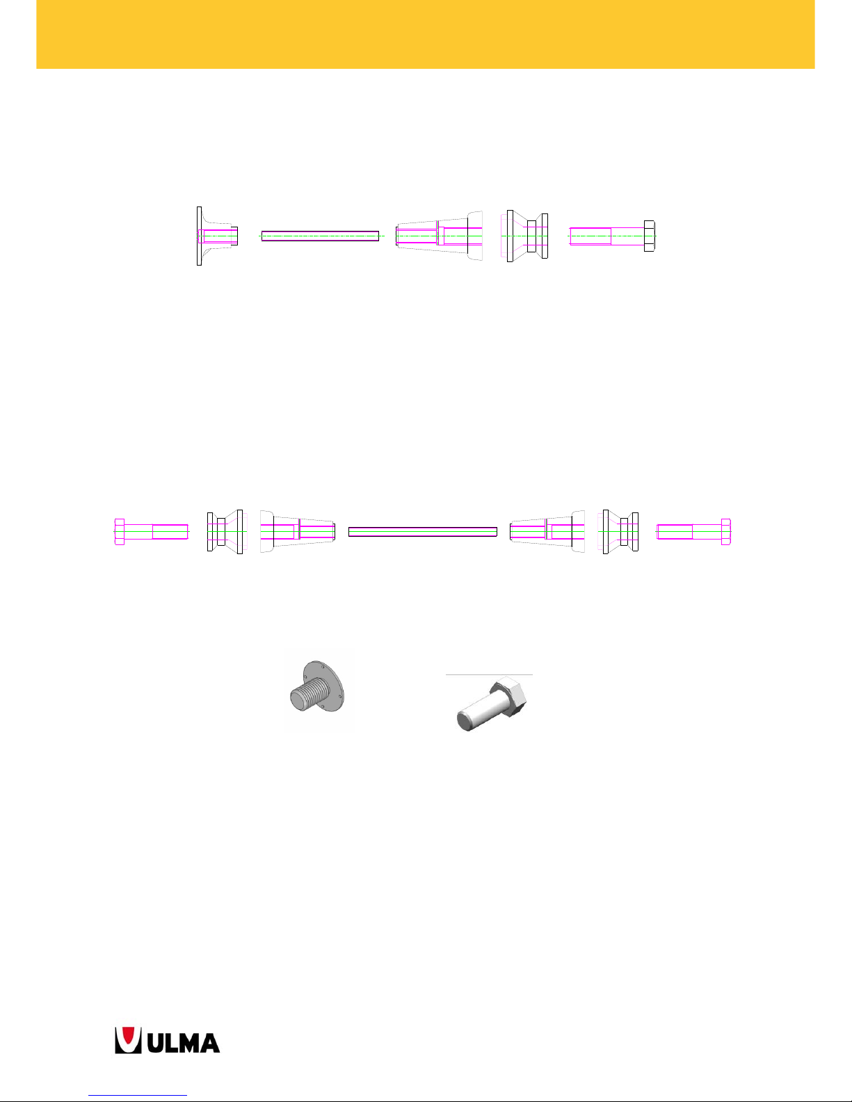
Anchorage DW 20
The set assembled of fixed anchor, tie rod DW20 and cone DW20/M30 remains embedded in the concrete and the
climbing ring NT20 is fastened to the set with the bolt M30x130. There is also the possibility to place two cones
face-to-face without the requirement of the fixed anchor.
To position the cone on the formwork panel (without using a bolt), the Cone Positioner M30 is used, and the
Positioner Spanner for its removal.
Cone Positioner M30 Positioner Spanner
(0238045) (1900211)
Special care has to be taken when tightening the bolts M30x130 as well as the tie rods DW20 and the fixed
anchors to ensure the effective transmission of loads from the structure to the concrete.
The positioning of the cones on the panels can be done in different ways:
Fixed Anchor
DW20
(
0238025
)
Tie Rod DW20
Cone DW20/M30
(
0238050
)
Climbing Ring NT
20
(
0238043
)
Bolt M30x130
(
0243013)
Tie Rod DW20
Cone DW20/M30
(
0238050
)
Climbing Ring NT
20
(
0238043)
Bolt M30x130
(
0243013
)
Page 66
66
BMK CLIMBING BRACKETS
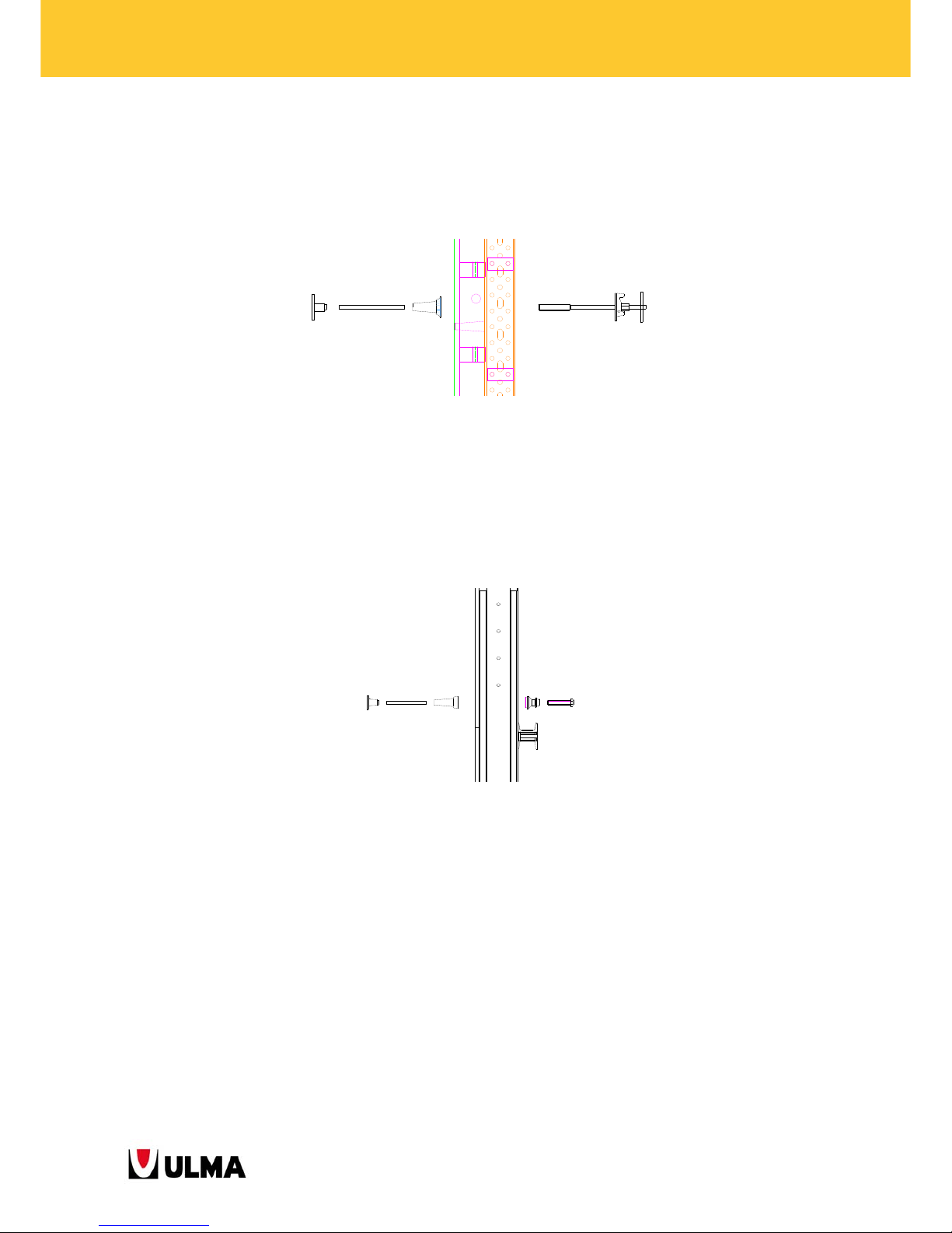
4.4.1. Drilling ORMA panel board
The shuttering face is drilled at the required position and dimension, d = 25 mm. Cone DW15/M24, tie rod DW15
and fixed anchor are placed on the shuttering face and fastened with the Cone-Waler Tie 90. The Tie passes
through the gap between the vertical waler profiles MK-120 and is fastened with the plate nut of the tie.
4.4.2. Drilling ENKOFORM panel board
The shuttering face is drilled at the required position and dimension. The corresponding cone DW, tie rod and
fixed anchor are assembled to each other, placed on the shuttering face and fastened with the climbing ring
and the bolt from the other side of the board.
4.4.3. Without drilling the board
If drilling holes into the shuttering face shall be avoided, this is the way to proceed:
The cone positioner is nailed to the board. Then the cone, the tie rod and the fixed anchor are assembled
to each other.
Page 67
67
BMK CLIMBING BRACKETS
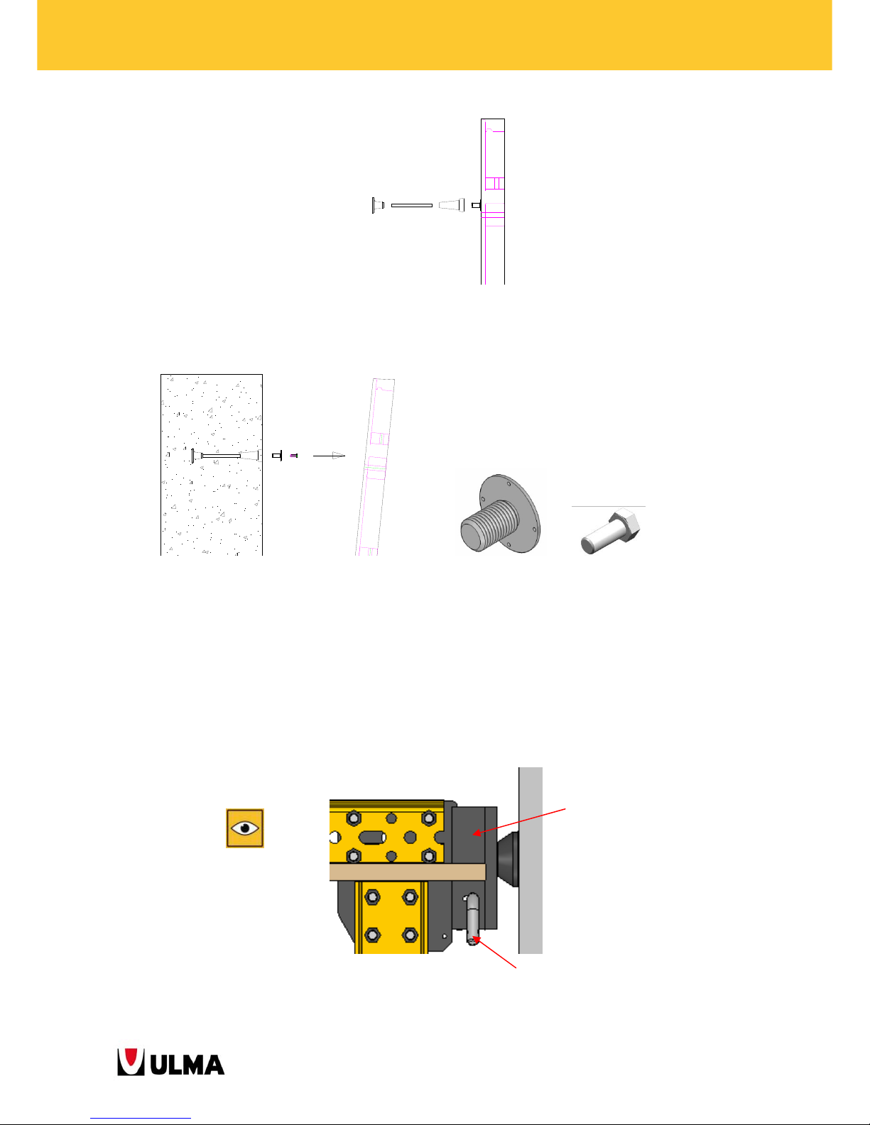
The formwork is removed from the concrete by reclining the panel. With the positioner spanner, the cone
positioner is removed from the cone
.
Special care has to be taken when tightening the bolts as well as the tie rods and the fixed anchors to ensure the
effective transmission of loads from the structure to the concrete.
4.4.4. Installation and securing of climbing brackets
Once the last anchorage is fastened to the wall, the climbing structure is supported on the anchors.
After having inserted the head into the climbing ring, the safety pin is placed and turned 90º thus clamping the
climbing bracket against any accidental uplifting.
Climbing bracket head
Safety pin turned 90º
Page 68
68
BMK CLIMBING BRACKETS
5. SYSTEM PROPERTIES
5.1. MAXIMUM SIZE OF FORMWORK PANEL
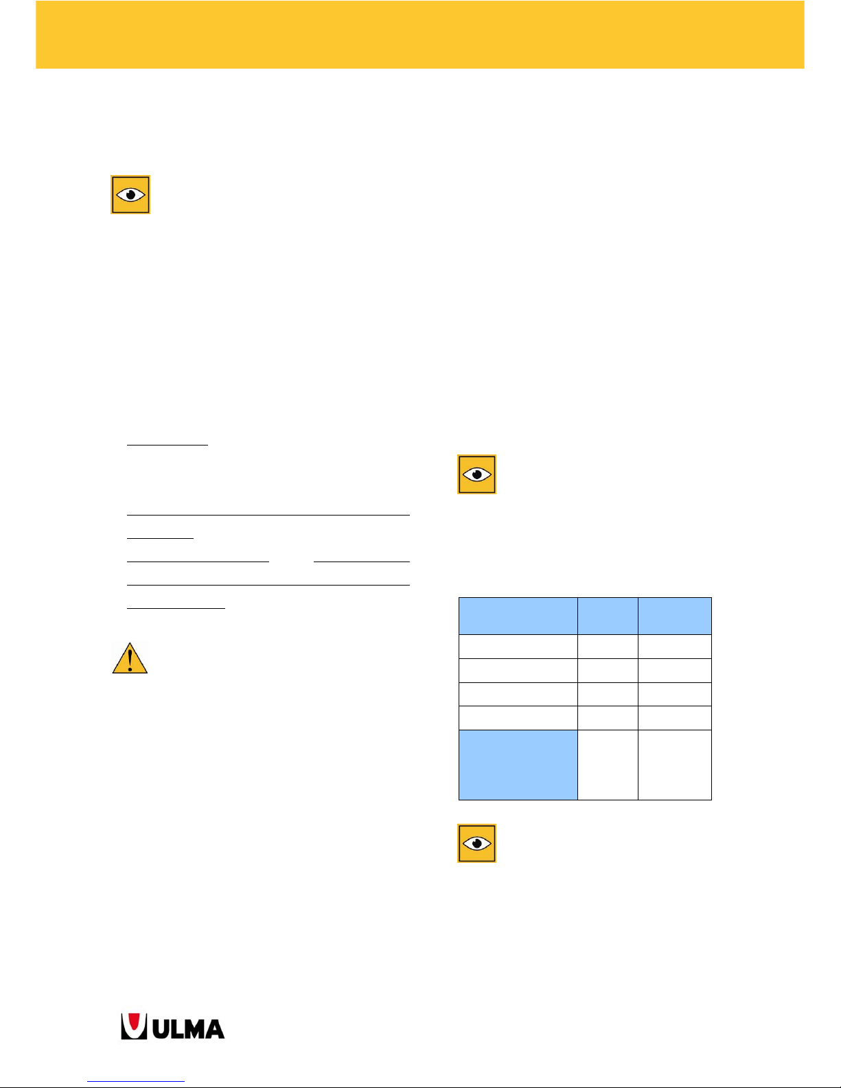
The system is designed to work under the following conditions:
Notes:
The maximum wind load is 0.2 kN/m² which corresponds to a wind speed of 64 km/h.
For wind speeds above 64 km/h, all activities on the climbing structure are abandoned and the workers leave
the platforms. Moreover, it is necessary to move the formwork towards the wall and block the roll-back
carriage with the Gear Locker MK (1991510) (see for details on page 16).
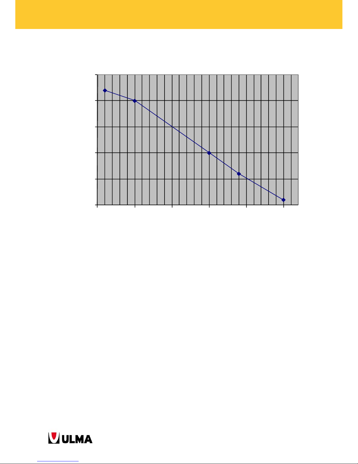
One limit of the climbing bracket BMK structure is relates to the maximum size of the formwork panel.
In the below chart, the relation between panel height and width of the climbing bracket BMK-240 is shown. It is
assumed that the length of the working platforms and the formwork panel width is the same.
This chart is valid only for a working height below 100m.
Working
(kN/m2)
Out-of-service
(kN/m2)
Concrete Pouring
Platform
1.5 0.75
Vertical Waler
Platform
0.75 0
Main platform 3.0 1.5
Cone Recovery
Platform
0.75 0
Wind Load 0.2 1.1
Page 69
69
BMK CLIMBING BRACKETS
HEIGHT-WIDTH LIMITS OF FORMWORK PANEL FOR THE CLIMBING BRACKET BMK-240
5.2. LIMITS OF ANCHORAGES
For each application, the loads to be borne by the anchors must be analysed individually. These depend on the selfweight, the live loads and the wind loads.
The anchor strength depends on the following factors:
Concrete strength
Cone DW20/M30 or DW15/M24 strength
Tie rod DW20 or DW15 strength
Bolt M30 DIN-931-10.9 or M24 DIN-931-10.9 strength
Through anchor or with Fixed Anchor DW20
Embedded anchor depth
Edge effects
Therefore, the limit of the anchorage varies for each anchorage configuration, so each anchorage in particular must
be studied.
2
2,5
3
3,5
4
4,5
3,544,555,56
Formwork pan el wid t h per bracket (m)
Formwork panel height (m)
Page 70
70
BMK CLIMBING BRACKETS
6. TERMS AND CONDITIONS OF
USE
The general terms and conditions of use can
vary. Therefore, those are defined for each application
in particular and included in the documentation for
each project.
Herein, serving as example only, the general terms
and conditions of use are outlined.
6.1. LOAD CASES
The following load cases are identified for the
climbing brackets BMK:
Working case:
when carrying out works such as
concrete pouring, placing steel reinforcement,
preparation and stripping. These works are
restricted to a permissible wind speed of 64 km/h
(0.2 kN/m2).
Out-of-service case (OS):
when wind speeds are
above the maximum permissible wind speed of 64
km/h (0.2 kN/m2).
When facing an out-of-service situation, the
following preventive measures must be taken to
ensure the safety of workers on the building site:
Evacuate all employees working on the climbing
bracket structure. Works must not continue on the
climbing formwork.
Tie any loose object of the climbing platforms.
In an out-of-service situation, the formwork panels
are moved against the wall and the stripping
systems blocked.
6.2. MAXIMUM WORKING LOADS
According to the load case, some maximum load
conditions are specified to which the system can be
submitted.
In each load case, permanent loads equal for all load
cases and variable loads differing according to the
load case are considered.
Subsequently, the loads to consider are specified:
Permanent loads:
o Self-weight of the structure
o Self-weight of the formwork panels
o Self-weight of the working platforms
Variable loads:
o Live loads on working platforms
o Wind loads (according to Eurocode 1)
The final values are specified in the
documentation of each application.
Serving as example, these are the loads to consider.
LIVE LOAD (kN/m²)
A
WORKING
C
OS
Pouring Platform 1.5 0.75
Vertical Waler Plat. 0.75 0
Main Platform 3 1.5
Cone Recovery Plat. 0.75 0
WIND (km/h)
64
According
to EC-1
(parts 1-
4).
The customer is responsible to check the wind
speed and the live loads on the platforms at all times.
Page 71
71
BMK CLIMBING BRACKETS
6.3. ANCHORAGE STRENGTH
For each application, the loads acting on each anchor
as well as the minimum strength which the concrete
must have to hold the elevating structure are
specified.
6.4. SAFE HANDLING GUIDELINES
6.4.1. BASIC SAFETY GUIDELINES ON SITE
Appropriate certified personal protective
equipment must be used to ensure the safety of
workers.
Always use:
o Safety helmet
o Gloves
o Safety boots
Where applicable and whenever necessary with
regard to the type of works carried out, use:
o Goggles or safety screens
o Hearing protection
o Breathing mask
o Safety harness
Adequate collective protection equipment (nets,
handrails, etc.) must be installed to ensure safe
working at height.
Observe an adequate tidiness and cleanliness of
formwork and climbing and formwork systems to
ensure their safe handling. The working platforms
are kept clean and tidy at all times, without tools,
bolts and any other parts in danger of falling from
them, and striking persons below.
Toeboards are placed at the outside face of the
platforms to prevent objects from falling to a lower
level. Moreover, safety nets can be installed at the
outside face of the platforms to prevent objects
from falling to a lower level. At the inside of the
platforms cover gaps with rubber or similar
material to prevent objects from falling to a lower
level. Avoid working below platforms where work
is carried out which might entail the hazard of
falling objects.
Access to and between platforms is ensured
exclusively by ladders installed for this purpose.
After having accessed a platform, the ladder hatch
must be closed. All ladders should project 1 m
above the platform to which they provide access.
Spread sawdust or sand on any slippery surface
caused by spilling (release agent, etc.).
6.4.2. System-specific safety instructions
All persons responsible for the operation of the
climbing system must be qualified and trained and
must have read the User's Guide before handling
the system. The User's Guide should be constantly
accessible for reference.
In the case of doubt or lack of information, please
contact the Technical Department of ULMA.
Travel sequences of the climbing system are carried
out under the supervision of the person in-charge
of the installation. This person must be trained for
the handling of climbing systems.
The employed crane must be of sufficient capacity
for the handling and assembly of the climbing
system parts.
Check and verify all cables and slings. The
maximum angles between the slings during lifting
may not exceed 60º.
Strictly avoid the Lifting Hook MK suffering strong
blows and crushing from handling, storage and
transport, and above all, from the handling of the
formwork with it.
Page 72

72
BMK CLIMBING BRACKETS
The Lifting Hook MK must be visually checked
before each use and removed from service, if not
working properly.
If the Lifting Hook MK experiences any sort of
deterioration during handling, it must be
immediately removed from service.
Before starting to lift the climbing brackets or
platforms, make arrangements to close the sides of
the platform to avoid falls from height.
No workers are allowed on the working platforms
during their lifting.
Ensure a steady and smooth travel of the climbing
structure. Avoid any sudden jerky movements.
Step back when lifting starts. Slightly lift the item
and check that the load is balanced and secured
correctly.
If not, lower the load again to the ground and
revise deficiencies.
Stand clear of suspended load. Do not guide
suspended load with your hands. To guide
suspended load, auxiliary means such as ropes
previously tied to the load are used.
Under the circumstances that the crane operator
has no visual control of the entire trajectory of the
load, the crane operations are guided by a
banksman who is in constant communication with
the crane operator by means of a previously agreed
sign code.
To prevent collision between platforms or brackets
during elevation, special attention must be paid to
the interferences between platforms and to any
object which could interfere in the elevation
movement of the system.
The entire structure with its components must get
assembled according to the instructions and
assembly drawings provided by ULMA. All bolts,
connections, tie rods, pins, etc. must be assembled
correctly.
All working platforms of the climbing system are
kept free from ice and snow, even when not in
use.
The maximum permissible wind speed for working
on the climbing system is 64 km/h (0.2 kN/m
2
). The
customer is responsible to check the wind speed at
each lifting operation and to evacuate the
platforms and to fix all platform components the
way they do not fall down, when wind speed is
rising.
For correct handling of the climbing system, the
customer shall ensure at all times a minimum
lighting of 100 lux in working areas, and
particularly in areas where the cylinder operation is
supervised.
In the out-of-service case, all employees working
on the climbing bracket structure must leave the
platforms. The formwork panels must be moved
against the wall and the climbing brackets fixed.
Before moving the roll-back carriages of the
climbing brackets, ensure that nobody remains
between wall or steel reinforcement and formwork
panel.
The moving of the formwork panel towards the
wall must be carried out with special care. Moving
the panels against the part of the concrete wall
from the previous pouring stage, can cause a prestressing or overloading of the climbing system
hence loading the climbing structure mainly the
screw jacks but also the anchors.
When moving the formwork panels against the
wall, it is very important to strictly follow the steps
indicated below:
o Move the panel close to the wall (2-3 cm
from the wall) with the roll-back carriage.
o Plumb the formwork panel with the push-
pull prop.
Page 73
73
BMK CLIMBING BRACKETS
o Adjust the vertical position of the formwork
panel with the levelling jack located at the
bottom of the vertical waler.
o Adjust the final position of the formwork
panel with the tie rods.
The use of the climbing system and the presence of
persons on the system is forbidden when the
weather forecast reports a storm with lightening.
If the building site is located nearby high voltage
power lines, it is recommended to work without
power supply. If this is not possible, the
appropriate measures according to the respective
reference standard should be taken.
It is of utmost importance to embed the anchors
into the concrete as indicated in the User's Guide
in order to correctly transmit the loads from the
structure to the concrete. The correct transmission
of the reactions in the anchors to the concrete is
responsibility of the customer. Only genuine
components of ULMA may be used to support and
anchor the climbing system. ULMA cannot be held
responsible for the use of material supplied by
third parties.
The live loads and maximum values of reactions in
the anchorages indicated in this guide must be
respected. Likewise, the minimum concrete
strengths indicated for the operation of the
climbing system must be respected. The customer
is responsible to control and check the concrete
strength.
6.4.3. Maintenance of the climbing system
Before assembling any system part, check that it is
in good working condition (rust, deformation,
etc.).
Periodically check the correct arrangement and
working of bolts, pins, wedges and joint
components, in general.
No alteration or change neither to the system
components nor to the assembly of the climbing
system is made without the approval and under
the supervision of ULMA personnel.
All welding which affects the operation of the
climbing system are carried out under the
supervision of personnel of ULMA.
Proper storage of the parts is fundamental to keep
them in good working condition.
6.4.4. Inspection instructions of lifting
appliances with CE marking of ULMA
Construcción
Before each use, the condition of the lifting
appliance must be checked, confirming the good
working condition of the following parts:
COMPONENT TO
CHECK
CORRECT WORKING
CONDITION
Ring Without deflection nor
excessive wear
Square bar Without deflection
Bolt Without deflection
ID plate Existing and legible
In case that the lifting appliance does not fulfil all
defined requirements, it must be removed from
service.
For more information, consult ULMA Construcción.
Page 74

74
BMK CLIMBING BRACKETS
7. Legal references
7.1. LEGAL REFERENCES
Council Directive 89/391/EEC of 12 June 1989 on the introduction of measures to encourage improvements in
the safety and health of workers at work
Council Directive 89/654/EEC of 30 November 1989 on the minimum safety and health requirements for the
workplace
Council Directive 89/656/EEC of 30 November 1989 on the minimum health and safety requirements for the
use by workers of personal protective equipment at the workplace
Council Directive 90/269/EEC of 29 May 1990 on the minimum health and safety requirements for the manual
handling of loads where there is a risk particularly of back injury to workers
Council Directive 92/57/EEC of 24 June 1992 on the implementation of minimum safety and health
requirements at temporary or mobile construction sites
Directive 92/58/EEC of 24 June 1992 on the minimum requirements for the provision of safety and/or health
signs at work
Directive 89/655/EEC of 30 November 1989 concerning the minimum safety and health requirements for the
use of work equipment by workers at work. Council Directive 95/63/EC of 5 December 1995 and Directive
2001/45/EC of the European Parliament and of the Council of 27 June 2001 amending formerly mentioned
Directive.
Directive 2002/44/EC of the European Parliament and of the Council of 25 June 2002 on the minimum health
and safety requirements regarding the exposure of workers to the risks arising from physical agents (vibration)
Directive 2003/10/EC of the European Parliament and of the Council of 06 February 2003 on the minimum
health and safety requirements regarding the exposure of workers to the risks arising from physical agents
(noise)
Directive 2006/42/EC of the European Parliament and of the Council of 17 May 2006 on machinery, and
amending Directive 95/16/EC (recast)
Page 75
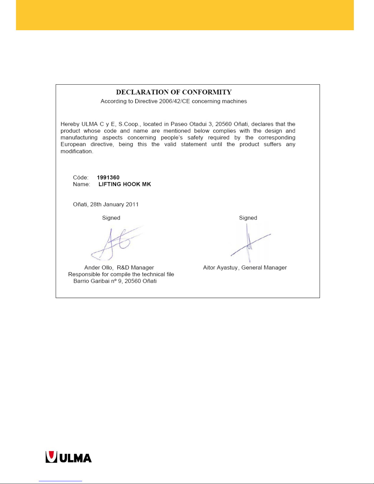
75
BMK CLIMBING BRACKETS
8. APPENDICES
8.1. DECLARATION OF CONFORMITY: LIFTING HOOK MK
Page 76
Chile
ULMA Chile - Andamios y
Moldajes, S.A.
SANTIAGO
www.ulma-c.cl
North Branch
ANTOFAGASTA
South Branch
CONCEPCIÓN
USA
ULMA Form Works, Inc.
HAWTHORNE - New Jersey
www.ulma-c.us
West Branch (Phoenix)
GILBERT - Arizona
Mid-Atlantic Branch
(Baltimore)
JESSUP - Maryland
Mexico
ULMA Cimbras y Andamios
de México S.A. de C.V.
TLALNEPANTLA
(Mexico State)
www.ulma-c.com.mx
Peru
ULMA Encofrados Perú, S.A.
LIMA
www.ulma-c.com.pe
North Branch
CHICLAYO - Lambayeque
ASIA-AFRICA
P.R. China
ULMA Formworks China R.O.
SHANGHAI
www.ulma-c.cn
UAE
ULMA Formworks UAE L.L.C.
DUBAI
www.ulma-c.ae
India
ULMA FORMWORK
SYSTEMS INDIA PVT. LTD.
GURGAON - Haryana
www.ulma-c.in
Mumbai Branch
MUMBAI - Maharashtra
Kazakhstan
ULMA Kazakhstan
ASTANA
www.ulma-c.kz
Singapore
ULMA Formwork Singapore
PTE. LTD.
SINGAPORE
www.ulma-c.sg
Slovac Republic
ULMA Construccion SK, s.r.o.
BRATISLAVA
www.ulma-c.sk
Romania
ULMA Cofraje s.r.l.
BUCHAREST
www.ulma-c.ro
Ukraine
ULMA Formwork Ukraine Ltd.
KIEV
www.ulma-c.ua
Dniepropetrovsk Branch
DNIEPROPETROVSK
Odessa Branch
ODESSA
AMERICA
Argentina
ULMA Andamios y
Encofrados Argentina, S.A.
FEDERAL CAPITAL
www.ulma-c.com.ar
Brazil
ULMA Brasil - Fôrmas e
Escoramentos Ltda.
ITAPEVI - SP
www.ulma-c.com.br
Rio de Janeiro Branch
ANIL - Rio de Janeiro - RJ
Brasilia Branch
GAMA - Brasilia DF
Bahia Branch
CIA SUL - Simões Filho
South Branch
NAVEGANTES - Porto Alegre RS
Minas Gerais Branch
FUNCIONÁRIOS - Belo
Horizonte MG
Canada
ULMA Construction Systems
Canada Inc.
BOLTON - Ontario
www.ulma-c.ca
Poland
ULMA contruccion Polska S.A.
WARSAW
www.ulma-c.pl
EAST REGION
Warsaw Branch
WARSAW
Olsztyn Branch
OLSZTYN
Łódź Branch
ŁÓDŹ
POZNAŃ BRANCH
Poznań Office
POZNAŃ
Bydgoszcz Office
BYDGOSZCZ
GDAŃSK BRANCH
Gdańsk Office
GDAŃSK
Szczecin Office
SZCZECIN
WROCŁAW BRANCH
Wrcoław Office
WRCOŁAW
Nowa Sól Office
NOWA SÓL
SOUTH REGION
Katowice Branch
JAWORZNO
Cracow Branch
CRACOW
Lublin Branch
LUBLIN
SCAFFOLDINGS BRACH
Warsaw Office
WARSAW
Płock Office
PŁOCK
Portugal
ULMA Portugal Lda.
SÃO JOÃO DA TALHA - Lisbon
www.ulma-c.pt
Oporto Branch
VILA NOVA DE GAIA - Oporto
Czech Republic
ULMA Construcción CZ, s.r.o.
BENÁTKY NAD JIZEROU
www.ulma-c.cz
EUROPE
Spain
ULMA C y E, S. Coop.
www.ulma-c.es
Canary Islands Branch
GÜIMAR (Tenerife)
Centre Branch
AJOFRÍN (Toledo)
East Branch
POLINYA (Barcelona)
North Branch
LEGUTIANO (Álava)
West Branch
CAMBRE (A Coruña)
South Branch
PELIGROS (Granada)
Germany
ULMA Betonschalungen und
Gerüste GmbH
RÖDERMARK
www.ulma-c.de
Northwest Branch
NEUSS
Southwest Branch
GÖPPINGEN
East Branch
ERFURT-WALTERSLEBEN
France
ULMA, S.A.R.L.
BONDOUFLE
www.ulma-c.fr
Paris Region Branch
BONDOUFLE
Lescar Branch
LESCAR
Events Branch
LONS
Tarnos Branch
TARNOS
Italy
ALPI, S.P.A.
MONGUELFO (BZ)
www.alpionline.net
PRODUCTION PLANT
AND HEADQUARTERS
ULMA C y E, S. Coop.
Ps. Otadui, 3 - P.O. Box 13
20560 OÑATI
SPAIN
Phone: +34 943 034900
Fax: +34 943 034920
www.ulma-c.com
 Loading...