

Installation Guide
Dual Zone Models
Wine Captain® Models:
2275ZWCS & 2275ZWCOL
Phone (414) 354-0300 • FAX (414) 354-7905
Service & Parts Tech Lines Phone (800) 779-2547 • FAX (414) 354-5696
www.U-LineService.com
OnlineService@U-Line.com
©2008 U-Line Corporation
03/2008
2275 Dual Zone WC Model
Contents
1-Follow Safety Precautions. . . . . . . . . . . . . . . . . . . . . . 2
Safety Alert Definitions . . . . . . . . . . . . . . . . . . . . . . . 2
General Precautions . . . . . . . . . . . . . . . . . . . . . . . . . . 2
2-Inspect and Plan . . . . . . . . . . . . . . . . . . . . . . . . . . . . . 3
Tools/Materials Required . . . . . . . . . . . . . . . . . . . . . . 3
Removing Protective Coating . . . . . . . . . . . . . . . . . . 3
Exterior Cleaning . . . . . . . . . . . . . . . . . . . . . . . . . . . . 3
3-Prepare The Site . . . . . . . . . . . . . . . . . . . . . . . . . . . . . 4
Cut-Out Dimensions . . . . . . . . . . . . . . . . . . . . . . . . . . 4
Product Dimensions . . . . . . . . . . . . . . . . . . . . . . . . . . 4
Door Swing/Clearances Information . . . . . . . . . . . . . 4
4-Other Site Requirements . . . . . . . . . . . . . . . . . . . . . . 4
5-Reversing the Door . . . . . . . . . . . . . . . . . . . . . . . . . . . 5
6-Side-By-Side Installation Instructions . . . . . . . . . . . . 6
7-Prepare Racks and Door Frame . . . . . . . . . . . . . . . . . 6
Rack Removal/Installation. . . . . . . . . . . . . . . . . . . . . . 7
8-Wood Trim Finishing . . . . . . . . . . . . . . . . . . . . . . . . . 7
Staining and Final Finish Application. . . . . . . . . . . . . 7
9-Overlay Frame (2275ZWCOL Only). . . . . . . . . . . . . . . 8
Frame Preparation. . . . . . . . . . . . . . . . . . . . . . . . . . . . 8
Preparing the New Overlay Panel . . . . . . . . . . . . . . . 9
Attaching the Overlay Panel. . . . . . . . . . . . . . . . . . . . 9
Assembling Door to Cabinet. . . . . . . . . . . . . . . . . . . . 10
10-Adjusting The Door. . . . . . . . . . . . . . . . . . . . . . . . . . 11
Checking Door Alignment . . . . . . . . . . . . . . . . . . . . . 11
Adjusting Door Alignment . . . . . . . . . . . . . . . . . . . . . 11
11-Prepare Power Supply. . . . . . . . . . . . . . . . . . . . . . . . 12
Electrical Specifications . . . . . . . . . . . . . . . . . . . . . . . 12
12-Level The Unit . . . . . . . . . . . . . . . . . . . . . . . . . . . . . . 12
Leveling Information . . . . . . . . . . . . . . . . . . . . . . . . . 12
Leveling Tip . . . . . . . . . . . . . . . . . . . . . . . . . . . . . . . . . 12
13-Install The Unit . . . . . . . . . . . . . . . . . . . . . . . . . . . . . 13
Anti-Tip Bracket Installation . . . . . . . . . . . . . . . . . . . . 13
Single Unit Installation . . . . . . . . . . . . . . . . . . . . . . . . 13
Side-By-Side Installation . . . . . . . . . . . . . . . . . . . . . . . 14
Installation Troubleshooting. . . . . . . . . . . . . . . . . . . . 14
14-Start-Up For The First Time. . . . . . . . . . . . . . . . . . . . 14
Initial Start-Up . . . . . . . . . . . . . . . . . . . . . . . . . . . . . . 14
Start-Up Troubleshooting . . . . . . . . . . . . . . . . . . . . . 14
15-Service Information . . . . . . . . . . . . . . . . . . . . . . . . . 14
1 Follow Safety Precautions
IMPORTANT
PLEASE READ all instructions completely before
attempting to install or operate the unit.
• This unit requires connection to a grounded (threeprong), polarized receptacle that has been placed by a
qualified electrician in accordance with applicable
electrical codes.
SAFETY ALERT DEFINITIONS
Safety items throughout this guide are labeled with a
Danger, Warning or Caution based on the risk type:
DANGER
Danger means that failure to follow this safety
statement will result in severe personal injury or
death.
WARNING
Warning means that failure to follow this safety
statement could result in serious personal injury,
or death.
CAUTION
Caution means that failure to follow this safety
statement may result in minor or moderate
personal injury, property or equipment damage.
GENERAL PRECAUTIONS
Use this appliance for its intended purpose only and
follow these general precautions along with those listed
throughout this guide:
WARNING
SHOCK HAZARD — Electrical Grounding Required.
• Keep the unit unplugged throughout installation
except during testing.
• Never remove the round grounding prong from
the plug and never use a two-prong grounding
adapter.
• Never use an extension cord to connect power to
the unit.
• Always keep your working area dry.
www.U-LineService.com 2 03/2008
CAUTION
• Use care when moving and handling the unit. Use
gloves to prevent personal injury from sharp
edges.
• Do not lift the unit by the door or door handle.
• Do not install the unit behind closed doors or in
any way that would obstruct airflow to the front
grille, which may cause the unit to malfunction.
2275 Dual Zone WC Model
2 Inspect and Plan
Inspect and Plan
You have received a carton containing your 2275ZWC or
2275ZWCOL with a package inside containing a Use and
Care Guide and a Product Registration Card and an AntiTip Bracket installation kit 2275ZWCOL units are shipped
with an additional package of hardware. Complete and
mail the Product Registration Card or register online at
www.U-LineService.com. Once your unit is installed, keep
the Use and Care Guide and this Installation Guide in a
safe place for future reference.
2275ZWC units are stainless steel. Stainless steel units are
covered with a protective coating and have been ordered
left- or right-hand hinged. The stainless doors are not
reversible.
2275ZWCOL units are black with a door that requires the
construction of a 3/4” thick wood overlay frame. You must
determine left- or right-hand opening before
construction.
All units come with maple trim racks that can be finished
or stained. Please carefully follow the directions that
apply to your unit and your intended design.
TOOLS/MATERIALS REQUIRED
• Screwdrivers — slotted and Phillips head
• Sandpaper; low odor, water clean up, quick drying
finish; tack cloth and, if desired, water-based wood
stain and synthetic foam brush.
• 3/4” overlay frame material, cutting tools, drill and bits
(2275ZWCOL units).
INSPECTION
Unwrap and inspect the unit on a flat, level surface
capable of supporting its entire weight.
REMOVING PROTECTIVE COATING
(Stainless Steel units only)
When inspecting/installing a stainless steel unit, the
protective coating covering the unit must be removed
first. Start at a corner of the unit/door and pull back the
protective coating to remove it from the unit/door.
After all the protective coating has been removed from
the unit/door, clean all stainless steel surfaces with Claire
Stainless Steel Polish and Cleaner or comparable product,
or a mild detergent and warm water solution and soft
cloth. DO NOT use abrasive cleaning agents.
Note: If cleaning with mild detergent and warm water
solution and soft cloth, the unit MUST be treated with
Claire Stainless Steel Polish and Cleaner or comparable to
prevent discoloration.
EXTERIOR CLEANING
(As Required)
Overlay Models:
• The door, grille and cabinet may be cleaned with a mild
detergent and warm water solution. Do not use
solvent-based or abrasive cleaners. Use a soft sponge
and rinse with clean water. Wipe with a soft, clean
towel to prevent water spotting.
Stainless Surfaces:
• Stainless door panels, handles and frames can discolor
when exposed to chlorine gas, pool chemicals, salt
water or cleaners with bleach.
• Clean any glass door fronts with a non-chlorine glass
cleaner.
• Keep your Stainless unit looking new by cleaning with
a good quality all-in-one stainless steel cleaner/polish
on a monthly basis. For best results use Claire Stainless
Steel Polish and Cleaner, which can be purchased from
U-Line Corporation. (The part number is 173348.)
Comparable products are acceptable. Frequent
cleaning will remove surface contamination that could
lead to rust. Some installations may require cleaning
on a weekly basis.
• Do not clean with steel wool pads.
• Do not use stainless steel cleaners/polishes on
any glass surfaces.
• Do not use cleaners that are not specifically
intended for stainless steel on stainless surfaces
(this includes glass, tile and counter cleaners).
• If any surface discolors or rusting appears, clean it
quickly with Bon-Ami or Barkeepers Friend Cleanser
and a non-abrasive cloth. Always clean in the direction
of the grain. Always finish this process with Claire
Stainless Steel Polish and Cleaner or comparable
product to prevent further problems.
• Use of abrasive pads such as Scotchbrite will
cause the graining in the stainless to become
blurred.
• Rust that is allowed to linger can penetrate into the
surface of the stainless steel and complete removal of
the rust may not be possible.
03/2008 3 www.U-LineService.com
2275 Dual Zone WC Model
3 Prepare The Site
Your U-Line product has been designed for either freestanding or built-in installation. When built-in, your unit
does not require additional air space for top, sides or rear.
However, the front grille must NOT be obstructed and
clearance is required for electrical connection in the rear.
Note: Unit can NOT be installed behind a closed cabinet
door.
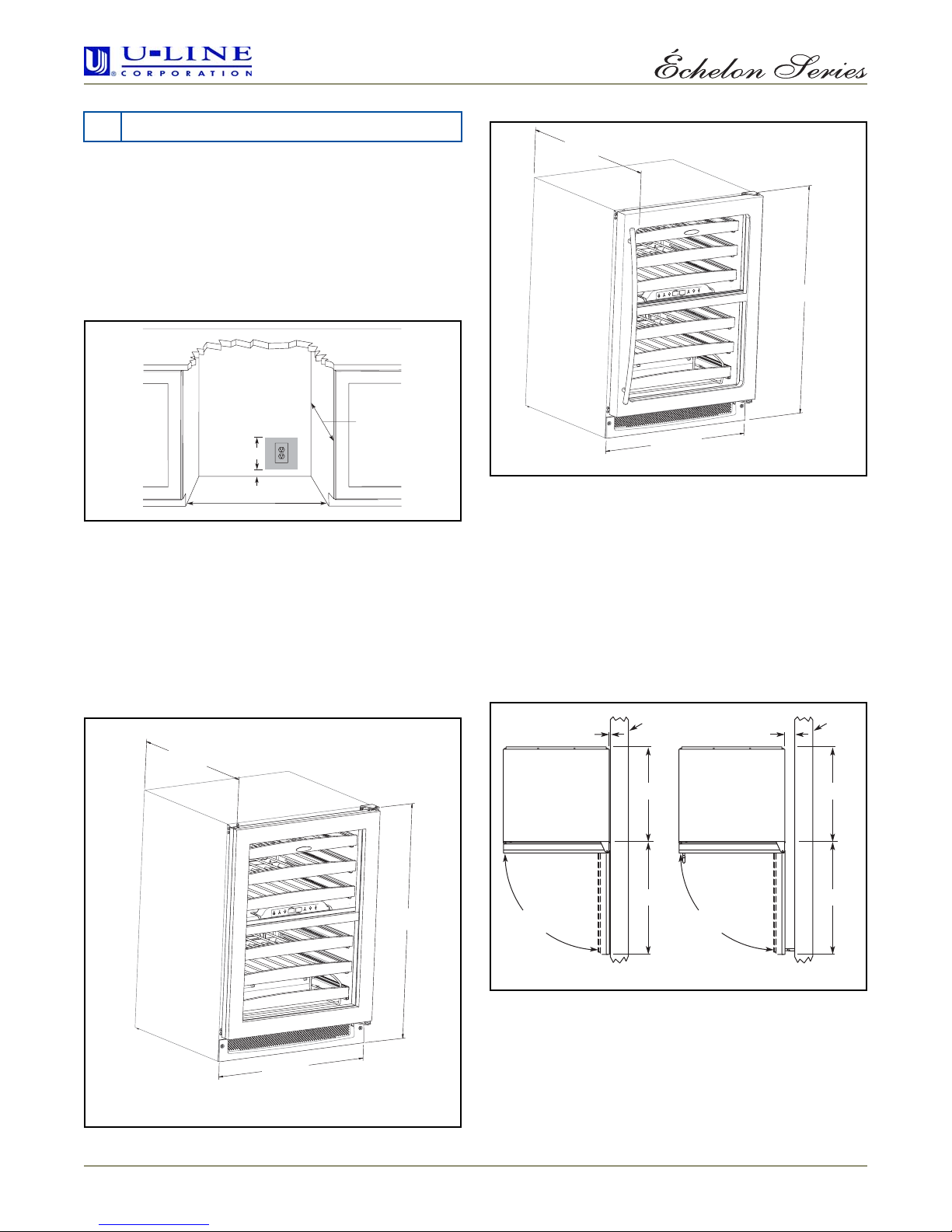
CUT-OUT DIMENSIONS
23-1/4"
7”
1-1/2”
24-3/16”
Figure 1
Follow the cut-out drawing in Figure 1. The 24-3/16"
width allows 1/4" for ease in installation and removal of
the unit. 24" is the cabinet depth in most installations.
The unit is 23-1/4" deep including wood overlay frame on
the 2275ZWCOL (Wood Overlay) model and 23-1/4” deep
including the door (but not the handle) on the 2275ZWCS
(Stainless Steel) models (Figure 2).
PRODUCT DIMENSIONS
23-1/4”
including wood overlay
25-3/8”
including
handle
34-1/8”
23-15/16”
2275ZWCSS
Figure 3
Note: The unit has adjustable feet that can add one
additional inch to height during leveling or to match
adjacent cabinets.
DOOR SWING/CLEARANCES INFORMATION
Wood overlay units have a zero clearance for the door to
open 90° (Figure 4). Stainless steel units require a
minimum of 2-1/8" door clearance to accommodate the
handle if the unit is installed next to a wall or similar type
of structure.
Wall Wall
2-1/8" Min.
23-15/16”
2275ZWCOL
Figure 2
www.U-LineService.com 4 03/2008
34-1/8”
90
Door Swing
Wood Overlay
21"
25-1/2"
Figure 4
90
Door Swing
21"
25-1/2"
Stainless Steel
2275 Dual Zone WC Model
4 Other Site Requirements
POWER SUPPLY
The unit requires a grounded and polarized 115 VAC,
60 Hz, 15A circuit (normal household current). See
Electrical Specifications.
ENVIRONMENTAL REQUIREMENTS
Many U-Line models are designed to operate in harsh
outdoor/marine environments. Special considerations
include the following:
• The units are designed to operate between 50°F (10°C)
and 110°F (40°C). High ambient temperatures (110°F
[40°C] or higher) may reduce the unit’s ability to reach
low temperatures.
• For best performance, keep the unit out of direct
sunlight and away from heat generating equipment.
• In climates where high humidity and dew points are
present, condensation may appear on outside surfaces.
This is considered normal. The condensation will
disappear when the humidity drops.
• U-Line does not recommend installation of glass front
models (Wine Captain
Beverage Centers) as well as the Combo Drawer model
(Refrigerator/Freezer/Ice Maker) outdoors, or in
tropical climates where high humidity and dew point
are present on a regular basis, unless air-conditioning
(typical 72°F, 75%RH) will be used.
®
wine storage models and
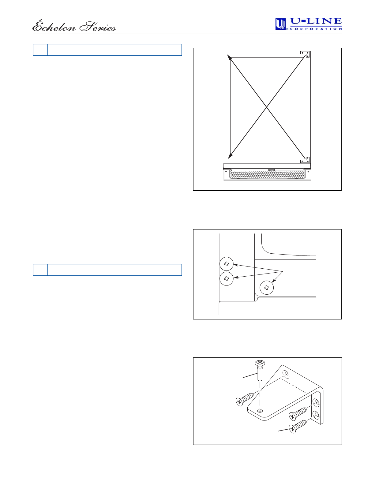
ULIN_0015_A
Figure 5
2.
Remove metal hinge plugs (3 each, top and bottom)
from new hinge location. Do not discard (
Figure 6
).
5 Reversing The Door
All U-Line units (except Stainless Steel models) may be
left- or right-hand opening. The door opening is easily
reversed by moving the hinge hardware to the opposite
side. The top hinge hardware will be used on the bottom
of the other side and the bottom hinge hardware will be
used on the top of the other side (see Figure 4).
To reverse the door:
1. Using a Phllips screwdriver, remove top hinge screw
pin from door (Figure 5). Remove door by tilting
forward and lifting off bottom hinge pin.
Hinge plugs
Figure 6
3. Remove top hinge (3 screws), reinstall hinge screw pin,
and remount on opposite side BOTTOM (
hinge screw
pin
hinge screws
ULIN_0003_A
Figure 7
).
03/2008 5 www.U-LineService.com
Figure 7
 Loading...