

U-Line U-ADA15IMB-00 Installation Manual
®
INSTALLATION GUIDE
ICEMAKER SERIES
U-ADA15IMB-00
U-ADA15IMS-00
U-ADA15IMS-01
BI2115ADA15IM BI98
U-BI2115B-00 U-BI2115SOD-00
U-BI2115B-20 U-BI2115SOD-01
U-BI2115S-00 U-BI2115SOD-20
U-BI2115S-01 U-BI2115SOD-22
U-BI2115S-20 U-BI2115W-00
U-BI2115S-22 U-BI2115W-20
BI95
ULN-BI95B-00
ULN-BI95B-20
ULN-BI95BTP-03
ULN-BI95BTP-20
ULN-BI95WH-00
ULN-BI95WH-20
ULN-BI98B-00
ULN-BI98B-20
ULN-BI98WH-00
ULN-BI98WH-20
ULN-SP18B-03
ULN-SP18B-20
ULN-SS1095FC-03
ULN-SS1095FC-20
ULN-SS1095FD-03
ULN-SS1095FD-20
ULN-SS1095NF-03
ULN-SS1095NF-20
SS98SS1095SP18
ULN-SS98-03
ULN-SS98-20
WH95
ULN-WH95TP-03
ULN-WH95TP-20
The American Built-In Undercounter Leader Since 1962
U-LINE.COM

Ta b l e o f C o n t e n t s
1 - Safety Precautions
Safety Alert Definitions.........................................................................................................................................1
General Precautions..............................................................................................................................................1
2 - Inspect & Plan
Product Registration .............................................................................................................................................2
Models Covered.....................................................................................................................................................2
Tools / Material Required ....................................................................................................................................2
Exterior Cleaning ...................................................................................................................................................2
3 - Prepare Site
Cut-Out Dimensions.............................................................................................................................................3
4 - Product Dimensions
Door Swing Dimensions.......................................................................................................................................7
5 - Other Site Requirements
Power Supply ..........................................................................................................................................................7
Water Supply ..........................................................................................................................................................7
Environmental Requirements..............................................................................................................................7
6 - Door Reversal
BI95 & BI98..............................................................................................................................................................8
WH95TP, BI95BTP, BCM95 & SP18 .................................................................................................................9
SS1095 ....................................................................................................................................................................10
7 - Door Panel Installation
Door Panel Preparation......................................................................................................................................12
Panel Dimensions.................................................................................................................................................12
Door Panel Installation (98, SP18, & ADA15)...............................................................................................12
8 - Adjust Door
Checking Door Alignment.................................................................................................................................13
Adjusting Door Alignment.................................................................................................................................13
9 - Power Supply
Electrical Specifications.......................................................................................................................................13
10 - Plumbing
Water Supply Connection .................................................................................................................................14
11 - Install
Leveling Information............................................................................................................................................15
Installation..............................................................................................................................................................15
Grille Installation ..................................................................................................................................................15
Installation Troubleshooting..............................................................................................................................16
ADA15IM Models ....................................................................................................................................... 3
BI-95(B)(WH) Models................................................................................................................................ 3
BI-98 / SS-98 Models .................................................................................................................................. 3
BI-2115 Models............................................................................................................................................ 3
SP-18 Models................................................................................................................................................ 3
SS-1095NF Models...................................................................................................................................... 4
SS-1095FC Models...................................................................................................................................... 4
SS1095FD...................................................................................................................................................... 4
BCM95 Models ............................................................................................................................................ 4
WH95TP Models ........................................................................................................................................ 4
BI95BTP......................................................................................................................................................... 4
ADA15IM BI95 BI95BTP BI98 BI2115.................................................................................................... 5
SS1095 SP18 BCM95 WH95.................................................................................................................... 6
NOTICE
DANGER
!
WARNING
!
CAUTION
!
1 Safety Precautions
General Precautions
Use this appliance for its intended purpose only. Follow these
general precautions with those listed throughout this guide:
• PLEASE READ all instructions before installing,
operating, or servicing the appliance.
• Proper installation procedures must be followed when
completing an installation or relocation of a unit. An
INSTALLATION GUIDE for the unit, providing
complete installation information, is available from
U-Line Corporation direct. Consult the installation
guide before any installation begins. U-Line contact
information appears on the rear cover of this guide.
• This unit requires connection to a dedicated 15 Amp
grounded (three-prong), polarized receptacle, installed
by a qualified electrician, compliant with applicable
electrical codes.
Safety Alert Definitions
Throughout this guide are safety items labeled with a Danger,
Warning or Caution based on the risk type:
Danger means that failure to follow this safety statement will
result in severe personal injury or death.
Warning means that failure to follow this safety
statement could result in serious personal injury or
death.
Caution means that failure to follow this safety statement
may result in minor or moderate personal injury, property
or equipment damage.
DANGER
!
RISK OF CHILD ENTRAPMENT. Before you throw away your
old refrigerator or freezer, take off the doors and leave shelves
in place so children may not easily climb inside.
WARNING
!
SHOCK HAZARD - Electrical Grounding Required.
• Never attempt to repair or perform maintenance on
the unit until the electricity has been disconnected.
• Never remove the round grounding prong from the
plug and never use a two-prong grounding adapter.
• Altering, cutting of power cord, removal of power
cord, removal of power plug, or direct wiring can
cause serious injury, fire and or loss of property and
or life, and will void the warranty.
• Never use an extension cord to connect power to the
unit.
• Always keep your working area dry.
WARNING
!
Install provided Anti-Tip kit. Serious personal injury
could occur.
CAUTION
!
• Use care when moving and handling the unit. Use gloves
to prevent personal injury from sharp edges.
• If your model requires defrosting, DO NOT use an ice
pick or other sharp instrument to help speed up
defrosting. These instruments can puncture the inner
lining or damage the cooling unit. DO NOT use any type
of heater to defrost. Using a heater to speed up
defrosting can cause personal injury and damage to the
inner lining.
NOTICE
• Do not lift unit by door handle.
• Never install or operate the unit behind closed doors.
Be sure front grille is free of obstruction. Obstructing
free airflow can cause the unit to malfunction and will
void the warranty.
• Failure to clean the condenser every six months can
cause the unit to malfunction. This could void the
warranty.
• Do not Block any internal Fans
Use only genuine U-Line replacement parts. Imitation
parts can damage the unit, affect its operation or
performance and may void the warranty.
u-line.com 1
2 Inspect & Plan
Product Registration
You have received a carton containing your ice maker unit with a
package inside containing a Use and Care Guide, a Product
Registration Card, and a water line kit. Please complete and
mail the Product Registration Card or register online at
www.U-LineService.com. Once your unit is installed, keep the Use
and Care Guide and this Installation Guide in a safe place for future
reference.
Models Covered
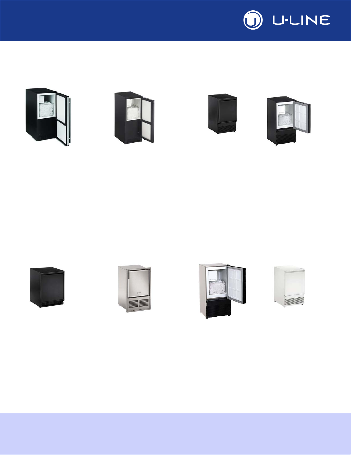
This installation guide covers the following models
Tools / Material Required
• Screwdrivers — slotted and Phillips head
• 1/4-inch thick door panel material and cutting tools (If installing
a 1/4" Panel)
• 1/4" Nut Driver
• 5/16" Nut Driver
• Side Cutter
• Copper tubing cutter
• 12" Level
• 9/16" Open end wrench
• 7/16" Open end wrench
• Pliers
• Copper tubing
A complete water hook up kit is also available for purchase from
your dealer. Order U-Line Part No. WATERHOOKUP.
U-ADA15IMB-00 ULN-BI98B-00
U-ADA15IMS-00 ULN-BI95WH-00
U-ADA15IMS-01 ULN-SP18B-03
U-BI2115B-00 ULN-SP18WH-03
U-BI2115S-00 ULN-SS1095FC-03
U-BI2115S-01 ULN-SS1095FD-03
U-BI2115SOD-00 ULN-SS1095NF-03
U-BI2115SOD-01 ULN-SS95-03
U-BI2115W-00 ULN-SS98-03
ULN-BI95B-00 ULN-WH95TP-03
ULN-BI95WH-00
Please carefully follow the directions that apply to your unit and
your intended design.
Exterior Cleaning
Black and White Models:
• Black and White surfaces may be cleaned with a mild detergent
and warm water solution. Do not use solvent-based or abrasive
cleaners. Use a soft sponge and rinse with clean water. Wipe
with a soft, clean towel to prevent water spotting.
Stainless Models:
• Stainless door panels, handles and frames can discolor when
exposed to chlorine gas, pool chemicals, salt water or cleaners
with bleach.
• Keep your Stainless unit looking new by cleaning with a good
quality all-in-one stainless steel cleaner/polish on a monthly
basis. For best results use Claire Stainless Steel Polish and
Cleaner, which can be purchased from U-Line Corporation
(Part numbers 173348). Frequent cleaning will remove surface
contamination that could lead to rust. Some installations may
require cleaning on a weekly basis.
• Do not clean with steel wool or abrasive pads.
• Do not use cleaners that are not specifically intended
for stainless steel on stainless surfaces (this includes
glass, tile and counter cleaners).
• If any surface discolors or rust appears, clean it quickly with
Bon-Ami or Barkeepers Friend Cleanser and a non-abrasive
cloth. Always clean in the direction of the grain. Always finish
this process with Claire Stainless Steel Polish and Cleaner or
comparable product to prevent further problems.
Rust that is allowed to linger can penetrate into the
surface of the stainless steel and complete removal of the
rust may not be possible.
2 u-line.com
CAUTION
!
NOTICE
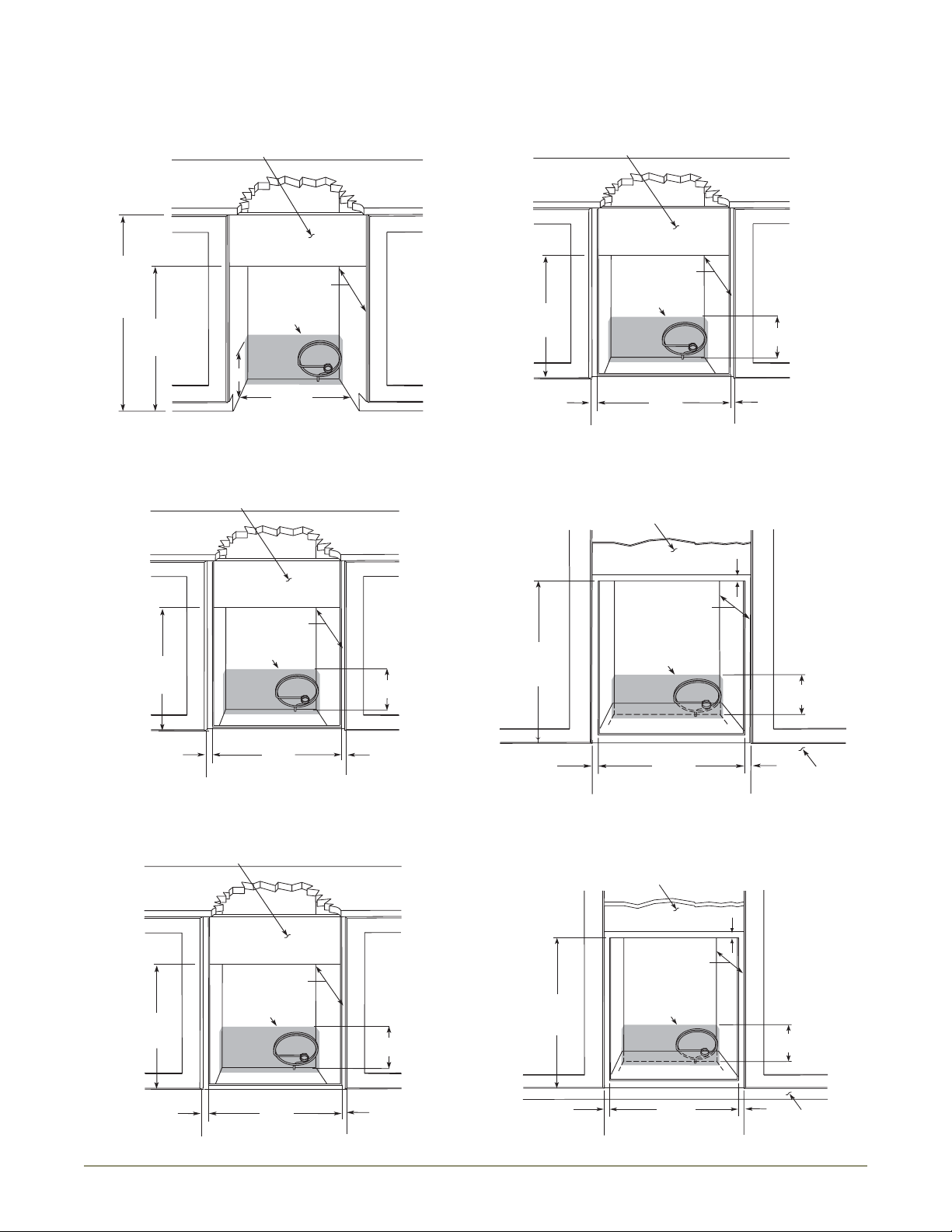
3 Prepare Site
23-3/4"
Minimum
15-1/4"
32"
to
33"
See Electrical
Specifications
for Power Supply
8"
8"
Typical
Counter
Height
34-1/4"
to
35-1/8"
Cut-Out
Height
25-1/16"
Filler Panel (Not Provided by U-Line) –
May Be Added Above or Below Unit
to Enclose for a Built-In Look
14-3/16"
18-1/2" Minimum
See Electrical
Specifications
for Power Supply
8"
Typical
Counter
Height
34-1/4"
to
35-1/8"
Cut-Out
Height
27-3/8"
Filler Panel (Not Provided by U-Line) –
May Be Added Above or Below Unit
to Enclose for a Built-In Look
15-3/16"
21-1/2"
Minimum
See Electrical
Specifications
for Power Supply
See Electrical
Specifications
for Power Supply
34-1/8"
to
35-1/8"
15-1/4"
8"
23-7/8"
Minimum
Cut-Out
Height
18-7/8"
26" Minimum
See Electrical
Specifications
for Power Supply
8" Height
From Floor
Filler Panel (Not Provided by U-Line) –
Needed to Attach Mounting Flange on Unit
k
14-1/4"
Cut-Out Width
3/4"
Minimum Flange
Mounting Area
3/4"
Minimum Flange
Mounting Area
3/4"
Minimum Flange
Mounting Area
Your U-Line product has been designed for either free-standing or
built-in installation. When built-in, your unit does not require
additional air space for top, sides or rear. However, the front grille
must NOT be obstructed and clearance is required for an
electrical and water connection in the rear.
Units can NOT be installed behind a closed cabinet door.
Cut-Out Dimensions
ADA15IM Models
BI-98 / SS-98 Models
BI-2115 Models
BI-95(B)(WH) Models
SP-18 Models
Toe Kic
u-line.com 3
SS-1095NF Models
8"
Typical
Counter
Height
34-1/4"
to
35-1/8"
Cut-Out
Height
25-1/16"
Filler Panel (Not Provided by U-Line) –
May Be Added Above or Below Unit
to Enclose for a Built-In Look
14-1/4"
18-1/2" Minimum
See Electrical
Specifications
for Power Supply
Cut-Out
Height
25-1/8”
Filler Panel (Not Provided by U-Line) –
Needed to Attach Mounting Flange on Unit
18-1/2” Minimum
See Electrical
Specifications
for Power Supply
8" Height
From Floor
14-1/4”
Cut Out Width
3/4”
Minimum Flange
Mounting Area
3/4”
Minimum Flange
Mounting Area
Cut-Out
Height
25-1/8”
Filler Panel (Not Provided by U-Line) –
Needed to Attach Mounting Flange on Unit
18-1/2”” Minimum
See Electrical
Specifications
for Power Supply
8" Height
From Floor
14-1/4”
Cut Out Width
3/4”
Minimum Flange
Mounting Area
3/4”
Minimum Flange
Mounting Area
Cut-Out
Height
26-1/16"
Filler Panel (Not Provided by U-Line) –
Needed to Attach Mounting Flange on Unit
18-1/2” Minimum
See Electrical
Specifications
for Power Supply
8" Height
From Floor
14-3/4”
Cut Out Width
3/4”
Minimum Flange
Mounting Area
3/4”
Minimum Flange
Mounting Area
Cut-Out
Height
25-1/8"
18-1/2" Minimum
See Electrical
Specifications
for Power Supply
8" Height
From Floor
Filler Panel (Not Provided by U-Line) –
Needed to Attach Mounting Flange on Unit
Toe Kick
14-1/4"
Cut-Out Width
3/4"
Minimum Flange
Mounting Area
3/4"
Minimum Flange
Mounting Area
3/4”
Minimum Flange
Mounting Area
Cut-Out
Height
25-1/16"
18-1/2" Minimum
See Electrical
Specifications
for Power Supply
8" Height
From Floor
Filler Panel (Not Provided by U-Line) –
Needed to Attach Mounting Flange on Unit
Toe Kick
14-1/4"
Cut-Out Width
3/4"
Minimum Flange
Mounting Area
3/4"
Minimum Flange
Mounting Area
3/4”
Minimum Flange
Mounting Area
SS-1095FC Models
BCM95 Models
WH95TP Models
SS1095FD
4 u-line.com
BI95BTP
 Loading...