

U-Line U-3018WCOL-00, U-3018WCOL-01, U-3024WCOL-00, U-3024WCOL-01, U-3036WCWCOL-00 Overlay Panels
...
®
OVERLAY PANEL GUIDE
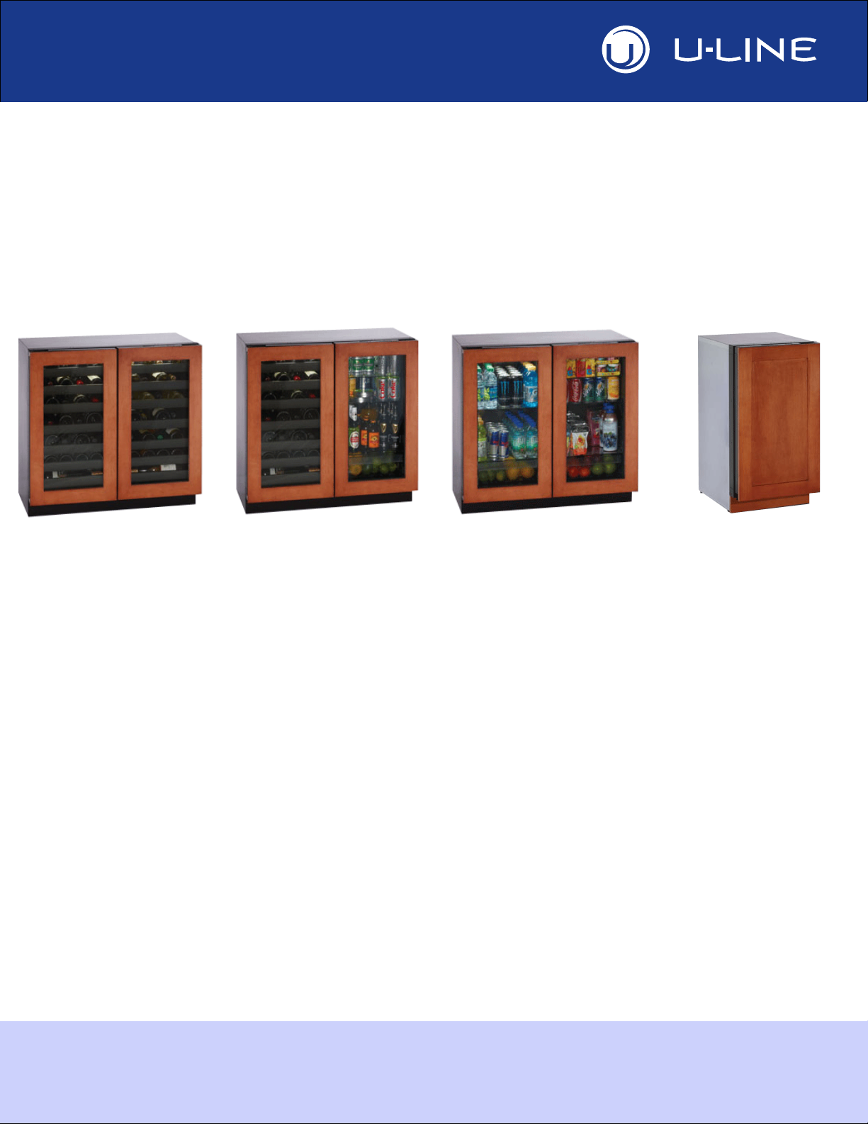
MODULAR 3000 SERIES
Overlay/Handleless Integrated Door Panel, Frame and Toe-Kick Specifications
WINE CAPTAIN®
MODELS
U-3018WCOL-00
U-3018WCOL-01
U-3024WCOL-00
U-3024WCOL-01
U-3036WCWCOL-00
BEVERAGE
CENTERS
U-3024BEVOL-00
U-3024BEVOL-01
U-3036BVWCOL-00
GLASS DOOR
REFRIGERATORS
U-3018RGLOL-00
U-3018RGLOL-01
U-3024RGLOL-00
U-3024RGLOL-01
U-3036RRGLOL-00
REFRIGERATORS/
ICE MACHINES
U-3018RFOL-00
U-3018RFOL-01
U-3024RFOL-00
U-3024RFOL-01
U-3036RROL-00
THE MODULAR 3000 SERIES ARE INTENDED FOR BUILT-IN INSTALLATIONS ONLY
The American Built-In Undercounter Leader Since 1962
U-3018CLROL-00
U-3018CLROL-01
U-3018CLROL-40
U-3018CLROL-41
U-LINE.COM

Ta b l e o f C o n t en t s
Safety Precautions
Safety Alert Definitions.........................................................................................................................................1
3000 Series Overlays
Overlay/Frame Overlay Panel.............................................................................................................................2
Handleless Integrated Door Panel/Frame Overlay ........................................................................................5
Overlay Grille .........................................................................................................................................................9
Panel Preparation........................................................................................................................................ 2
Overlay & Frame Overlay Panel Dimensions....................................................................................... 2
Panel Installation.......................................................................................................................................... 3
Panel/Frame Overlay Preparation ........................................................................................................... 5
Handleless Overlay Dimensions for 18" and 36" Units ..................................................................... 6
Handleless Overlay Dimensions for 24" Units..................................................................................... 7
Panel/Frame Installation............................................................................................................................. 8
Overlay Preparation................................................................................................................................... 9
Overlay Installation..................................................................................................................................... 9
Overlay Grille Dimensions .................................................................................................................... 10
DANGER
!
WARNING
!
CAUTION
!
Safety Precautions
Safety Alert Definitions
Throughout this guide are safety items labeled with a Danger,
Warning or Caution based on the risk type:
Danger means that failure to follow this safety statement will
result in severe personal injury or death.
Warning means that failure to follow this safety
statement could result in serious personal injury or
death.
Caution means that failure to follow this safety statement
may result in minor or moderate personal injury, property
or equipment damage.
u-line.com 1

NOTICE
3000 Series Overlays
BACK SURFACE MUST HAVE AMPLE FLAT SURFACE
TO MOUNT OVERLAY PANEL FLAT AND WITHOUT
INTERFERENCE
BACK SURFACE MUST HAVE AMPLE FLAT SURFACE
TO MOUNT OVERLAY FRAME FLAT AND WITHOUT
INTERFERENCE
17-1/2"
(445 mm)
3/4"
(19 mm)
3/4"
(19 mm)
Solid Overlay
2-3/4" MIN
(70 mm MIN)
30"
(762 mm)
Frame Overlay
17-1/2"
(445 mm)
30"
(762 mm)
3018 and 3036 Models
Overlay/Frame Overlay Panel
Due to differences in surrounding cabinetry the panel may
not perfectly align with door. The procedure below is
designed to provide a finished overlay panel that
seamlessly integrates with surrounding cabinetry.
Panel Preparation
A full overlay door panel completely covers the door frame and
provides a built-in appearance.
Overlay & Frame Overlay Panel Dimensions
NOTICE
• The door panel must not weigh more than 20 lbs
(9.1 kg).
• It is important to ensure that all drilled holes are drilled
to the correct depth in order to avoid splits in the wood
when hardware is installed.
• Appliance will need up to 34-1/2" (876.3 mm) to the
under side of the counter to leave room for leveling
adjustments.
1. Cut the panels to the dimensions listed in the appropriate
diagram below.
2. Optional: Stain or Finish panel to desired stain or color. Be sure
to closely follow the instructions provided by the manufacturer.
3. Optional: Install handles and hardware.
NOTICE
When applying an overlay panel/frame to a unit, ensure
that both sides are finished in order to prevent warping. In
some overlay panel/frame installations, the overlay may be
visible through the glass while the door is open.
2 u-line.com

BACK SURFACE MUST HAVE AMPLE FLAT SURFACE
TO MOUNT OVERLAY PANEL FLAT AND WITHOUT
INTERFERENCE
BACK SURFACE MUST HAVE AMPLE FLAT SURFACE
TO MOUNT OVERLAY FRAME FLAT AND WITHOUT
INTERFERENCE
23-3/8"
(594 mm)
3/4"
(19 mm)
Solid Overlay
30"
(762 mm)
2-3/4" MIN
(70 mm MIN)
Frame Overlay
3/4"
(19 mm)
3024 Models
23-3/8"
(594 mm)
30"
(762 mm)
Display
Cable
Inner Door
Channel
Panel Installation
1. Fully open door.
2. Starting at corner, pull gasket
away from door.
3. Continue to pull gasket free
from gasket channel.
4. Upon removal, lay gasket
down on a flat surface.
NOTICE
If working with the door that houses the display, make
certain the display cable remains securely seated in the
inner door channel, see below.
u-line.com 3

5. The frame should be aligned with the outside edge (opposite the
NOTICE
Align Frame
Against
Door Edge
First
Align Top Of Panel With Highest Point Of Door
Door
Frame
Wood
Panel / Frame
Door
Bar
Clamp
Bar
Clamp
Overlay Panel
Overlay Panel
hinge) and high enough to align with the highest point in the
door.
Due to differences in floor construction or surrounding
cabinetry, the frame may not sit flush with the top of the
door.
10. Be sure the screws force their way past the opening on the
gasket channel and sit flush against the bottom of the channel.
11. Remove clamps from door.
NOTICE
If frame requires additional adjustment after removing
clamps, slightly loosen each screw and adjust frame as
necessary. Tighten screws upon completion.
12. Starting at the corners, re-install the gasket into the gasket
channel in the frame. Make sure the gasket is fully seated. This
may take some force.
13. If installing an additional overlay on a 36" unit, repeat steps 1
through 12 on the opposite door.
6. Secure overlay to
door using clamps. A
robust tape may also
be used. U-Line
recommends the use
of bar clamps to
securely clamp the
overlay to the door. If
using tape, be certain
the tape will not
damage overlay finish
upon removal.
7. Using a 7/64" drill bit,
drill 6 pilot holes into
the wood panel
1/2" deep using the
holes in the door
frame as a guide.
8. Locate 6 of the #6x
1-1/2" screws
provided with your
unit.
9. Using a Phillips
screwdriver, place one
screw into each of the
6 pilot holes and
screw down. Do not
overtighten screws.
4 u-line.com

Handleless Integrated Door Panel/
NOTICE
Top Design
and Insert Notch
Wooden Insert
Main Panel
Cutout
Panel Overlay
Frame Overlay
Main Panel
Wooden Insert
Top Design
and Insert Notch
Frame Overlay
The following procedure is designed to provide a finished,
handleless solid panel or frame overlay for an 18" or 24" door that
seamlessly integrates with its surrounding cabinetry. Prepare two
18" overlays for 36" units.
NOTE: Many cabinet manufacturers provide a ready solution for a
handle-less, integrated design that can be easily applied to your
U-Line 3000 Series model. Consult your cabinet manufacturer for
applicable design and installation details. The cabinet
manufacturer’s solution to this design and integration detail will
often result in an overlay panel/frame solution wherein the size of
the panel/frame may result in a height dimension taller than what
we specify. This can be achieved provided the additional height is
positioned above the appliance door.
• The panel / frame overlay aligns with the surrounding
cabinetry and, due to differences in cabinetry, may not align
perfectly with the door.
• The appliance will need up to 34-1/2" to the underside of the
counter to leave room for leveling adjustments.
• A single prepared overlay with insert must not weigh more
than 20 lbs.
Panel/Frame Overlay Preparation
1. Cut the main panel(s) to the appropriate dimensions below.
For details, see the drawings on the following pages.
• For 18" or 36" units, see page 6.
• For 24" units, see page 7.
Unit width Panel width Panel depth
18" or 36"* 17-1/2" 28-13/16"
24" 23-3/8" 28-13/16"
*Two 18" panels are required for 36" units.
2. Create the top design for the handleless feature and the 1/8"
notch for the insert(s) indicated on the appropriate Top Detail
drawing, page
3. For
4. Prepare the insert(s) that will back up the handleless design.
Wooden Insert
appropriate dimensions below.
Unit width Insert width Insert depth
18" or 36"* 17-1/2" 3-1/2"
24" 23-3/8" 3-1/2"
*Two 18" inserts are required for 36" units.
2
or 3.
Frame Units
, create the indicated cutout(s), page 6
– Cut 1/8" thick wooden insert(s) to the
or 7.
u-line.com 5

Handleless Overlay Dimensions for 18" and 36" Units
3/4"
28-13/16"
2-3/4"
2-3/4"
R 5/8"
1/8"
1/4"
Wooden Insert
Notch Depth: 1/8"
2-3/8"
7/8"
Ref.
Cutout
for Frame
Units
Top Detail
Insert Notch, 1/8"
Top Design
1/8"
3-1/2"
17-1/2"
Wooden Insert Dimensions
17-1/2"
6 u-line.com

Handleless Overlay Dimensions for 24" Units
3/4"
28-13/16"
2-3/4"
2-3/4"
R 5/8"
1/8"
1/4"
Wooden Insert
Notch Depth: 1/8"
2-3/8"
7/8"
Ref.
Cutout
for Frame
Units
Top Detail
Insert Notch
Top Design
1/8"
3-1/2"
23-3/8"
Wooden Insert Dimensions
23-3/8"
u-line.com 7

5. Optional: Stain or finish panel / frame and wooden insert to
NOTICE
NOTICE
Attach Wooden Insert
Display
Cable
Inner Door
Channel
Align Frame
Against
Door Edge
First
Align Top Of Panel With Highest Point Of Door
Door
Frame
desired stain or color. Be sure to closely follow the instructions
provided by the manufacturer.
If finishing overlay or wooden insert, all sides must be
finished to prevent warping.
6. Attach the insert to the panel / frame. Wood glue or equivalent
adhesive should be used to attach insert to panel / frame.
4. Align the prepared overlay panel / frame to the door — first
along the side of the door furthest from the hinge and then top
align with the door’s highest point.
NOTICE
Due to differences in floor construction or surrounding
cabinetry, the overlay may not sit flush all the way along
the top of the door.
Panel/Frame Installation
1. Fully open the door.
2. Starting at the corner, pull gasket away
from gasket channel in door.
3. When gasket is completely free from
channel, lay it on a flat surface.
Make certain the display cable remains securely seated in
the inner door channel, as shown below.
5. Secure overlay to door using clamps or a robust tape.
Note:
U-Line recommends securely attaching the overlay using
bar clamps. If using tape, be certain tape will not damage the
overlay finish.
6. Using a 7/64" drill bit, drill 6 pilot holes into the overlay 1/2"
deep using the holes in the door as a guide.
NOTICE
It is important to ensure that all drilled holes are drilled to
the correct depth in order to avoid splits in the wood
when hardware is installed.
7. Locate 6 of the #6x 1-1/2" screws provided with your unit.
8. Using a Phillips screwdriver, place one screw into each of the 6
holes and screw in. Do not overtighten.
8 u-line.com

NOTICE
11. Starting at the corner, re-install
Overlay
Panel / Frame
Bar Clamp
Door
Bar Clamp
Overlay Panel Overlay Panel
Apply Tape To Shaded Area
the gasket into the gasket channel
in the frame, making sure the
display cable is undisturbed. Also
make sure the gasket is fully
seated. This may take some force.
12. If installing overlays on a
repeat steps 1 through 11 for the
opposite door.
36" unit
,
Overlay Grille
The 3000 series grille is fully adjustable and can be set to match
your surrounding cabinetry dimensions. In addition to its
adjustability, an overlay may also be installed to truly provide a
seamless appearance.
Overlay Preparation
1. Use the dimensions provided in the diagram on page 10 to cut
and shape your grille overlay. Recommended overlay thickness
is between 1/4" and 3/8". Dimension A will vary based on your
toe kick height.
2. Finish or stain your grille overlay to match your surrounding
cabinetry. Both sides require finishing to prevent warping. Be
certain to carefully follow the finish manufacturer’s
recommendations for application and cure times.
9. Make sure the screws force their way past the opening on the
10. Remove clamps from door.
If overlay requires additional adjustment after removing
clamps, slightly loosen each screw and adjust alignment as
necessary. Tighten screws upon completion.
gasket channel and sit flush against the bottom of the channel.
NOTICE
If finishing grille overlay, all sides must be finished to
prevent warping.
3. Apply double sided tape to the backside of the overlay grill. Use
the diagram below for reference. U-Line recommends 3M
VHB™ tape, a high strength bonding tape.
Overlay Installation
1. Remove backing paper from double sided tape.
2. Carefully align grille over overlay and press into position.
™
u-line.com 9

Overlay Grille Dimensions
3036 Models
1"
35-7/16"
32-7/16"
Recommended Overlay Grille Thickness is 1/4" and May Not Exceed 3/8"
3024 Models
1"
23-5/8"
20-5/8"
3018 Models
1"
1-1/2"
17-3/4"
14-3/4"
3-5/16"
to
4-5/16"
1-1/2"
1-1/2"
1-1/2"
1-1/2"
1-1/2"
3-5/16"
to
4-5/16"
3-5/16"
to
4-5/16"
10 u-line.com

®
OVERLAY PANEL GUIDE
PRODUCT INFORMATION
Complete Installation Guides, Use and Care Guides, Specifications & Features and Benefits, CAD Drawings,
Overlay Panel/Frame and Toe-Kick Specifications and Instructions, Compliance Documentation and Applicable
Energy Guides are available for reference and download at u-line.com.
SERVICE INFORMATION
Please consult your Use and Care Guide for troubleshooting information. Answers to Customer Frequently Asked
Questions are available at u-line.com under Customer Service. You may contact U-Line directly:
GENERAL INQUIRIES:
U-Line Corporation
P.O. Box 245040
Milwaukee, Wisconsin 53224-9540 U.S.A.
Phone 1-414-354-0300
FAX 1-414-354-7905
Email: sales@u-line.com
u-line.com
SERVICE ASSISTANCE:
Phone 1-800-779-2547
FAX 1-414-354-5696
Email: onlineservice@u-line.com
u-lineservice.com
PARTS ASSISTANCE:
E-mail: onlineparts@u-line.com
BUILDING ON THREE GENERATIONS OF INNOVATION
For over five decades and through three generations, U-Line continues to be the leader in innovation, quality and
performance in the premium built-in undercounter ice making, refrigeration and wine preservation market. U-Line
has captivated those with an appreciation for the finer things with exceptional functionality, style, inspired
innovation and attention to even the smallest details. We are known and respected for our unwavering dedication
to product design, quality and selection.
In 1962, Henry Uihlein founded U-Line Corporation as an outgrowth of Ben-Hur Freezer Company and was the first
to develop and patent an automatic stand-alone undercounter residential ice maker. His foresight and determination
to develop new ideas and to succeed when there were no clear guidelines or solutions are evident today. The newest
Uihlein generation continues to build upon the family’s innovative legacy at the Milwaukee, Wisconsin based business
by providing continuity and vision from which new designs and technology continue to be born.
Today the complete U-Line product collection includes Ice Makers, Ice Machines, Wine Captain® Models, Combo®
Models, Refrigerator / Freezers, Refrigerators, Drawer Models and Beverage Centers. The U-Line brand offers
products in the 1000 Series, 2000 Series and the Modular 3000 Series. The 1000 Series offers a more targeted
priced product with appropriate features, while the 2000 Series offers upscale features, advanced technology and
specialized product families. Our Modular 3000 Series provides sleek design and versatile temperature settings with
our U-Select® control. U-Line’s approach to its breadth of products, multiple price points and features allows a
choice and product that will fit any lifestyle.
DESIGNED, ENGINEERED AND ASSEMBLED IN WISCONSIN, USA
The American Built-In Undercounter Leader Since 1962
U-LINE.COM
Publication Number 30349 10/2013 Rev.G
©2013 U-Line Corporation
 Loading...