

Page 1
Para Español, vea páginas 5-8.
Pour le français, consulter les pages 9-12.
π H-1297, S-11507
®
PURE FLOW 1000
1-80 0-295-5510
uline.com
EYEWASH STATION
GENERAL INFORMATION
The H-1297 shipping carton should contain:
• Eye Wash Station
• Emergency Sign
• Hanging Bracket
Before installing S-11507 Pure Flow 1000® Saline Cartridges, inspect product for damage.
NOTE: S-11507 Pure Flow 1000® Saline Cartridges are sold separately.
CARTRIDGE INSTALLATION
NOTE: This eyewash station requires two saline
cartridges to be installed at the same time.
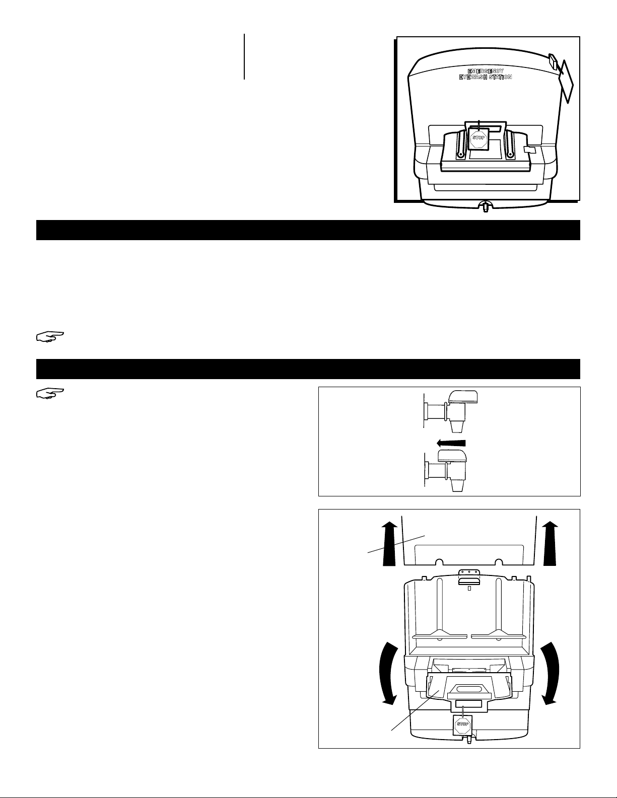
1. Close the drain spigot by turning handle to the rear.
(See Figure 1)
2. Remove cover by lifting up. (See Figure 2A) Open
activating door. (See Figure 2B)
Figure 1
Open
Closed
Figure 2A
Cover
Figure 2B
Activating Door
PAGE 1 OF 12 0915 I H -1297
Page 2
CARTRIDGE INSTALLATION CONTINUED
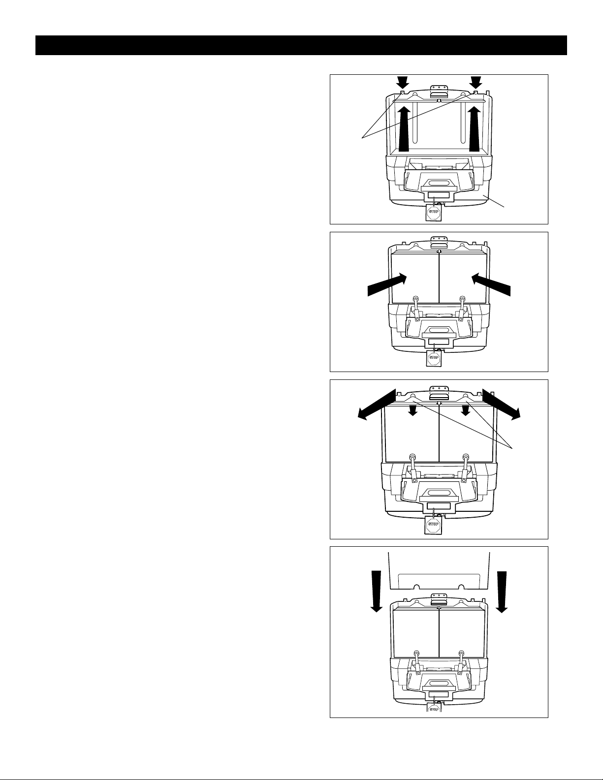
3. Raise reservoir to "Up" position, latch on housing by
pressing back on latching tabs. (See Figure 3)
4. Place two S-11507 Pure Flow 1000® Saline Cartridges
on the shelf. Nozzle assembly must be in front.
(See Figure 4)
Figure 3
Latching
Tabs
Reservoir
Figure 4
5. Pull green latch tabs forward to drop down reservoir,
ensuring that plates are seated on bags and are not
resting on the cartridge boxes. (See Figure 5)
6. Replace cover. (See Figure 6)
Figure 5
Reservoir
Plates
Figure 6
PAGE 2 OF 12 0915 I H -1297
Page 3

CARTRIDGE INSTALLATION CONTINUED
7. Remove rubber bands from activating strap and
nozzle. Extend activating straps to the side. Do not
pull on the straps. (See Figure 7)
8. Snap right-hand nozzle into place on white nozzle
plate. An audible 'click' will be heard to confirm that
the nozzle is engaged. (See Figure 8)
Figure 7
Figure 8
9. Snap left-hand nozzle into place on white nozzle
plate. An audible 'click' will be heard to confirm that
the nozzle is engaged. (See Figure 9)
10. Position the two black straps over top of the
activation door with the expiration date and batch
number visible. Do not twist or cross straps. Close
activation door. (See Figure 10)
Figure 9
Figure 10
PAGE 3 OF 12 0915 I H -1297
Page 4
CARTRIDGE INSTALLATION CONTINUED
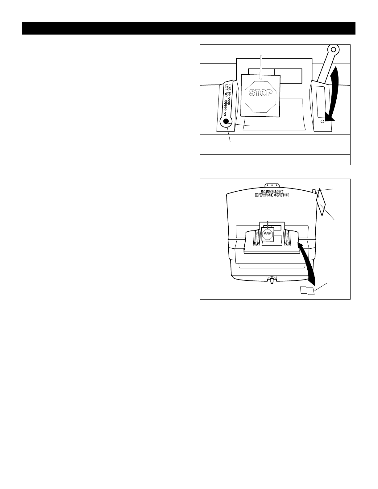
11. Position nozzle activating straps over top of door and
down raised area on either side of the door handle
so the straps cover the labels on the activation door.
(See Figure 11)
12. Push plastic fastener into hole in door until flange is
seated against the door. (See Figure 11)
13. Push center pin of fastener until it snaps into place
flush with fastener head. (See Figure 11)
14. Position tamper seal on middle right-hand side of
door. Half the seal must be on the door and the
other half on the unit surface. (See Figure 12)
15. Attach lock or inspection tag through tab on cover.
(See Figure 12)
Fig ure 11
Figure 12
Center Pin
Plastic Fastener
Tab
Inspection
Tag
Tamper
Seal
π
CHICAGO • ATLANTA • DALLAS • LOS ANGELES • MINNEAPOLIS • NYC/PHILA • SEATTLE • MEXICO • CANADA
1-800-295-5510
PAGE 4 OF 12 0915 I H -1297
uline.com
Page 5

π H-1297, S-11507
®
PURE FLOW 1000
01-800-295-5510
uline.mx
ESTACIÓN LAVAOJOS
INFORMACIÓN GENERAL
La caja de la unidad H-1297 debe contener:
• Estación Lavaojos
• Letrero de Emergencia
• Soporte de Instalación
Antes de instalar los cartuchos de solución salina S-11507 Pure Flow 1000®, revise el producto para verificar que no
haya daños.
NOTA: Los cartuchos de solución salina S-11507 Pure Flow 1000® se venden por separado.
INSTALACIÓN DEL CARTUCHO
NOTA: Esta estación lavaojos requiere que se
instalen dos cartuchos de solución salina a la vez.
1. Cierre de boquilla de drenaje girando el asa hacia
la parte posterior. (Vea Diagrama 1)
2. Quite la cubierta levantándola. (Vea Diagrama 2A)
Abra la puerta de activación. (Vea Diagrama 2B)
Diagrama 1
Abierto
Cerrado
Diagrama 2A
Cubierta
Diagrama 2B
Puerta de
Activación
PAGE 5 OF 12 0915 I H -1297
Page 6

CONTINUACIÓN DE INSTALACIÓN DEL CARTUCHO
3. Coloque el depósito en la posición "Up" (Arriba)
y trabe la cubierta presionando las pestañas de
bloqueo hacia atrás. (Vea Diagrama 3)
4. Coloque en la repisa dos cartuchos de solución
salina S-11507 Pure Flow 1000®. El ensamble de la
boquilla debe estar en la parte frontal.
(Vea Diagrama 4)
Diagrama 3
Pestañas de
Bloqueo
Depósito
Diagrama 4
5. Jale las dos pestañas de bloqueo verdes hacia
adelante para bajar el depósito, asegurándose de
que las placas queden asentadas sobre las bolsas
y no descansen sobre las cajas de los cartuchos.
(Vea Diagrama 5)
6. Vuelva a colocar la cubierta. (Vea Diagrama 6)
Diagrama 5
Placas del
Depósito
Diagrama 6
PAGE 6 OF 12 0915 I H -1297
Page 7

CONTINUACIÓN DE INSTALACIÓN DEL CARTUCHO
7. Quite las ligas de goma de la correa de activación
y la boquilla. Extienda las correas de activación
hacia los lados. No jale las correas.
(Vea Diagrama 7)
8. Inserte la boquilla derecha en su lugar sobre la
placa con boquilla blanca ejerciendo presión.
Escuchará un clic que confirma que la boquilla
está colocada. (Vea Diagrama 8)
Diagrama 7
Diagrama 8
9. Inserte la boquilla izquierda en su lugar sobre la
placa con boquilla blanca ejerciendo presión.
Escuchará un clic que confirma que la boquilla
está colocada. (Vea Diagrama 9)
10. Coloque las dos correas negras sobre la parte
superior de la puerta de activación con la fecha
de caducidad y el número de lote visibles. No gire
ni cruce las correas. Cierre la puerta de activación.
(Vea Diagrama 10)
Diagrama 9
Diagrama 10
PAGE 7 OF 12 0915 I H -1297
Page 8

CONTINUACIÓN DE INSTALACIÓN DEL CARTUCHO
11. Coloque las correas de activación de las boquillas
sobre la puerta y hacia abajo de la zona elevada
de cada uno de los lados del asa de la puerta,
de forma que las correas cubran las etiquetas
adhesivas de la puerta de activación.
(Vea Diagrama 11)
12. Inserte los cinchos de plástico en los orificios de la
puerta hasta que la brida quede asentada contra
la puerta. (Vea Diagrama 11)
13. Ejerza presión sobre la clavija central del cincho
hasta que se inserte en su lugar al ras con la
cabeza del cincho. (Vea Diagrama 11)
14. Coloque el sello a prueba de alteraciones sobre la
sección central del lado derecho de la puerta. La
mitad del sello deberá estar sobre la puerta y la
otra mitad sobre la superficie de la unidad.
(Vea Diagrama 12)
15. Coloque un seguro o una etiqueta de inspección a
través de la pestaña de la cubierta. (Vea Diagrama 12)
Diagrama 11
Diagrama 12
Clavija Central
Cincho de Plástico
Lengüeta
Etiqueta de
Inspección
Sello a
Prueba de
Alteraciones
π
CHICAGO • ATLANTA • DALLAS • LOS ANGELES • MINNEAPOLIS • NYC/PHILA • SEATTLE • MEXICO • CANADA
01-800-295-5510
PAGE 8 OF 12 0915 I H -1297
uline.mx
Page 9

π H-1297, S-11507
MD
PURE FLOW 1000
–
1-80 0-295-5510
uline.ca
STATION DE LAVAGE
DES YEUX
RENSEIGNEMENTS GÉNÉRAUX
La boîte d'expédition (H-1297) doit contenir:
• Station de lavage des yeux
• Affiche de sécurité
• Support de suspension
Avant d'installer les cartouches de solution saline Pure Flow 1000MD (S-11507), inspectez le produit pour vous assurer
qu'il n'est pas endommagé.
REMARQUE: Les cartouches de solution saline Pure Flow 1000MD (S-11507) sont vendues séparément.
INSTALLATION DE LA CARTOUCHE
REMARQUE: Deux cartouches de solution
saline doivent être installées en même temps
sur cette station de lavage des yeux.
1. Fermez le robinet en tournant la poignée vers
l'arrière. (Voir Figure1)
2. Retirez le couvercle en le soulevant. (Voir Figure2A)
Ouvrez la porte d'activation. (Voir Figure2B)
Figure1
Ouvert
Fermé
Figure 2A
Couvercle
Figure 2B
Porte d'activation
PAGE 9 OF 12 0915 I H -1297
Page 10

INSTALLATION DE LA CARTOUCHE SUITE
3. Soulevez le réservoir vers le haut, puis accrochez-le
au boîtier en appuyant sur les crans de verrouillage.
(Voir Figure3)
4. Placez deux cartouches de solution saline Pure Flow
1000MD (S-11507) sur la tablette. Les buses doivent
être à l'avant. (Voir Figure4)
Figure3
Crans de
verrouillage
Réservoir
Figure4
5. Tirez sur les crans de verrouillage verts pour abaisser
le réservoir en vous assurant que les plaques
s'appuient sur les sacs et ne reposent pas sur les
cartouches. (Voir Figure5)
6. Replacez le couvercle. (Voir Figure6)
Figure 5
Plaques de
réservoir
Figure6
PAGE 10 OF 12 0915 I H -1297
Page 11

INSTALLATION DE LA CARTOUCHE SUITE
7. Retirez les bandes élastiques de la courroie
d'activation et de la buse. Étendre les courroies
d'activation sur le côté. Ne tirez pas sur les courroies.
(Voir Figure7)
8. Encliquetez la buse de droite en place sur la plaque
de buse blanche. Un déclic audible confirmera que
la buse est bien en place. (Voir Figure8)
Figure7
Figure8
9. Encliquetez la buse de gauche en place sur la
plaque de buse blanche. Un déclic audible
confirmera que la buse est bien en place.
(Voir Figure9)
10. Placez les deux courroies noires au-dessus de la
porte d'activation en vous assurant que la date
d'expiration et le numéro de lot sont visibles. Évitez
d'entortiller ou d'entrecroiser les courroies. Fermez
la porte d'activation. (Voir Figure10)
Figure9
Figure10
PAGE 11 OF 12 0915 I H -1297
Page 12

INSTALLATION DE LA CARTOUCHE SUITE
11. Placez la buse d'activation des courroies sur
le dessus de la porte et vers le bas sur la zone
surélevée sur chaque côté de la poignée de
porte de façon à ce que les courroies couvrent les
étiquettes sur la porte d'activation. (Voir Figure11)
12. Poussez l'attache en plastique dans le trou de la
porte jusqu'à ce que la bride soit appuyée contre la
porte. (Voir Figure11)
13. Poussez la tige du centre de l'attache jusqu'à ce
qu'elle s'enclenche au ras de la tête de l'attache.
(Voir Figure11)
Figure11
Tige du centre
Attache en plastique
14. Placez le scellé d'inviolabilité au milieu du côté droit
de la porte. La moitié du scellé doit se trouver sur la
porte et l'autre moitié sur la surface de l'unité.
(Voir Figure12)
15. Fixez le verrou ou l'étiquette d'inspection à travers le
cran situé sur le couvercle. (Voir Figure12)
Figure12
Cran
Étiquette
d'inspection
Scellé
d'inviolabilité
π
CHICAGO • ATLANTA • DALLAS • LOS ANGELES • MINNEAPOLIS • NYC/PHILA • SEATTLE • MEXICO • CANADA
1-800-295-5510
PAGE 12 OF 12 0915 I H -1297
uline.ca
 Loading...