

Page 1
π
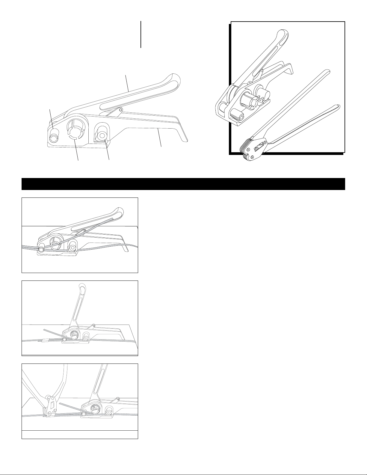
Tension Lever
H-702, H-703
STRAPPING TENSIONERS
AND SEALERS
Cutter Wheel
H-57, H-540, H-572
Para Español, vea página 2.
Pour le français, consulter la page 3.
1-80 0 -295 -5510
uline.com
Base Handle
Windlass
Gripper Plate
Figure 1
OPERATION
THREADING TENSIONER (See Figure 1)
1. Wrap both ends of strapping around product.
2. Squeeze handle and base together.
3. Insert the shorter end of strapping under the gripper plate and cutter
wheel leaving approximately 5" of strapping off the front end.
4. Release handle and base.
5. Feed the other end through the cutter wheel and up through the windlass.
6. Pull strapping as tight as possible.
TENSIONING (See Figure 2)
1. Move tension lever forward and back to begin tensioning.
2. Continue back and forth motion until strapping has reached desired
tension.
PLACING THE SEAL
1. Seal should be placed open side down on top of both ends of strapping.
Figure 2
SEALING (See Figure 3)
1. Close nose of sealer around seal.
2. Crimp tightly around strapping.
REMOVING EXCESS
1. Squeeze handle and base together to cut strapping.
2. Slide tool off to the right.
MAINTENANCE
Tools do need to be cleaned and maintained periodically with a steel brush or
Figure 3
PAGE 1 OF 3 0414 IH- 540
π
CHICAGO • ATL ANTA • DALL AS • LOS ANGELES • MINNEAPOLIS • N YC/PHIL A • SEATTLE • MEXICO • CANADA
dry compressed air. Lubricate all moving parts with light machine oil.
Page 2

π
H-702, H-703
TENSIONADORAS Y
SELLADORAS PARA FLEJE
Palanca Tensionadora
Rueda de corte
Molinete Placa de agarre
H-57, H-540, H-572
01-800-295 - 5510
uline.mx
Mango de la base
FUNCIONAMIENTO
Diagrama 1
Diagrama 2
COLOQUE FLEJE EN TENSIONADORA (Vea Diagrama 1)
1. Envuelva ambos extremos del fleje alrededor del producto.
2. Apriete juntos el mango y la base.
3. Inserte el extremo corto del fleje debajo de la placa de agarre y la rueda
de corte dejando aproximadamente 13 cm (5") de fleje por el extremo
frontal.
4. Suelte el mango y la base.
5. Inserte el otro extremo a través de la rueda de corte y arriba a través del
molinete.
6. Jale el fleje lo más ajustado posible.
TENSIONE (Vea Diagrama 2)
1. Mueva la palanca tensionadora hacia adelante y atrás para
comenzar a tensionar.
2. Continúe con movimientos hacia atrás y adelante hasta que el fleje haya
alcanzado la tensión deseada.
COLOQUE EL SELLO
1. El sello deberá ser colocado con el lado abierto hacia abajo por arriba
de ambos extremos del fleje.
SELLE (Vea Diagrama 3)
1. Cierre la nariz de la selladora alrededor del sello.
2. Apriete firmemente alrededor del fleje.
CORTE EL EXCESO
1. Apriete juntos el mango y la base para cortar el fleje.
2. Sague la herramienta deslizándola a la derecha.
MANTENIMIENTO
Las herramientas necesitan ser limpiadas y darles mantenimiento
Diagrama 3
PAGE 2 OF 3 0414 IH- 540
π
CHICAGO • ATL ANTA • DALL AS • LOS ANGELES • MINNEAPOLIS • N YC/PHIL A • SEATTLE • MEXICO • CANADA
periódicamente con un cepillo de acero o aire seco comprimido. Lubrique
las partes móviles con aceite ligero para máquina.
Page 3

π
Levier de tension
H-702, H-703
TENDEURS DE FEUILLARD
ET SCELLEURS
Roue de couteau
Bourriquet Plateau de préhenseur
H-57, H-540, H-572
1-80 0 -295 -5510
uline.ca
Poignée de base
FONCTIONNEMENT
Figure 1
Figure 2
ENFILAGE DU SERTISSEUR (Voir Figure1)
1. Entourer le produit avec les deux extrémités du feuillard.
2. Serrer la poignée et la base ensemble.
3. Insérer l'extrémité plus courte du feuillard sous le plateau du préhenseur
et la roue du couteau en laissant environ 13 cm (5 po) de feuillard sur
l'extrémité avant.
4. Relâcher la poignée et la base.
5. Alimenter l'autre extrémité dans la roue du couteau et remonter vers le
bourriquet.
6. Tirer pour serrer le feuillard autant que possible.
SERRAGE (Voir Figure2)
1. Déplacer le levier de tension vers l'avant et l'arrière pour
commencer le serrage.
2. Continuer le mouvement avant arrière jusqu'à ce que le feuillard soit à la
tension désirée.
POSE DU JOINT
1. Le joint doit être placé avec le côté ouvert vers le bas sur les deux
extrémités du feuillard.
SCELLER (Voir Figure3)
1. Fermer le nez de la scelleuse autour du joint.
2. Sertir fermement autour du feuillard.
RETIRER L'EXCÉDENT
1. Serrer la poignée et la base ensemble et couper le feuillard.
2. Glisser l'outil vers la droite.
ENTRETIEN
Les outils doivent être nettoyés et entretenus régulièrement avec une brosse
Figure 3
PAGE 3 OF 3 0414 IH- 540
π
CHICAGO • ATL ANTA • DALL AS • LOS ANGELES • MINNEAPOLIS • N YC/PHIL A • SEATTLE • MEXICO • CANADA
métallique ou de l'air comprimé. Lubrifier toutes les pièces mobiles avec de
l'huile mouvement.
 Loading...