

Page 1
Para Español, vea páginas 3-4.
Pour le français, consulter les pages 5-6.
H-4124
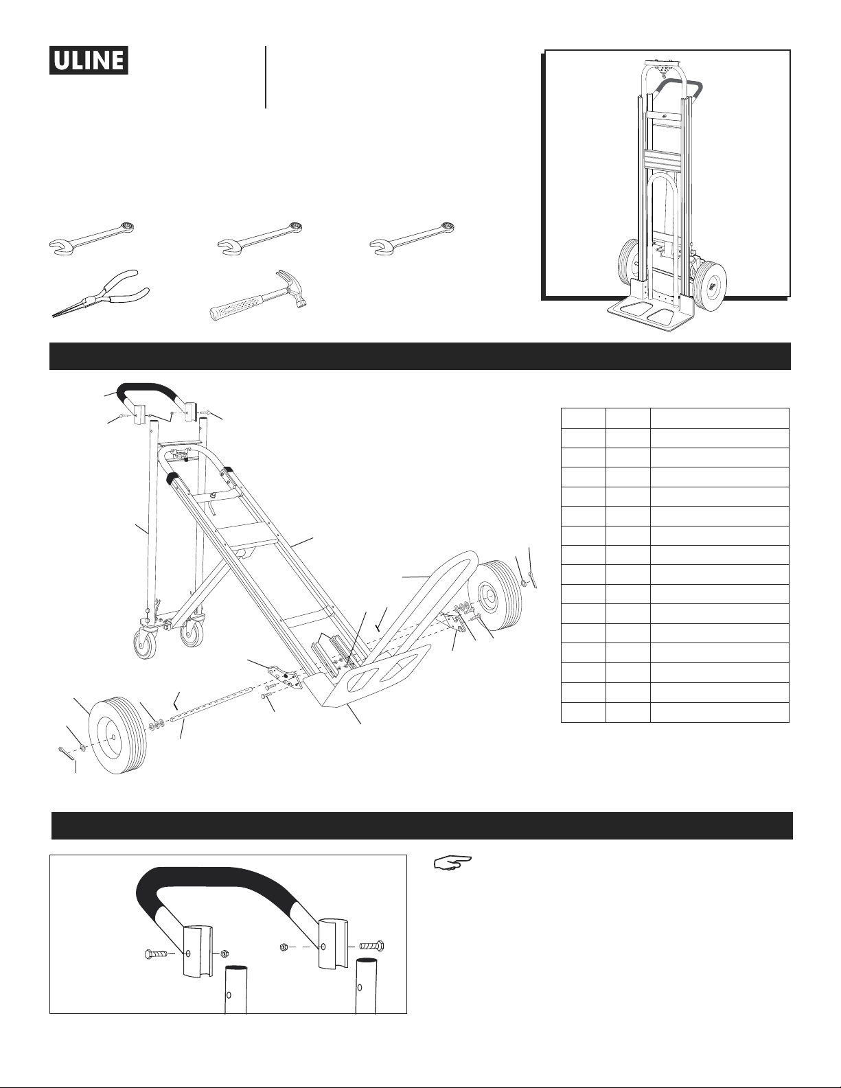
3-IN-1 ALUMINUM
HAND TRUCK
WITH SOLID RUBBER WHEELS
TOOLS NEEDED
10mm Wrench 13mm Wrench 14mm Wrench
Pliers
1
2
7
6
3
4
9
6
8
2
11
1-80 0-295 -5510
uline.com
Hammer
4
13
12
10
14
PARTS
15
9
11
REF. QTY. DESCRIPTION
1 1 Handle
2 2 6mm Bolt
3 2 6mm Locknut
4 1 Frame
5 2 Cotter Pin
5
6
6
10
6 8 Washer
7 2 Wheel
8 1 Axle
9 2 Round Pin
10 4 8mm Bolt
11 2 Axle Support
12 2 Frame Reinforcement
13 4 8mm Locknut
14 1 Nose Plate
15 1 Folding Nose Extension
5
ASSEMBLY
Figure 1
ATTACH HANDLE
1. Slide handle onto the top rails of the frame. Align
PAGE 1 OF 6 0421 IH-4124
NOTE: Do not use air or power tools.
holes in handle and frame. Insert two 6mm bolts
through handle and frame and secure with locknuts.
(See Figure 1)
Page 2
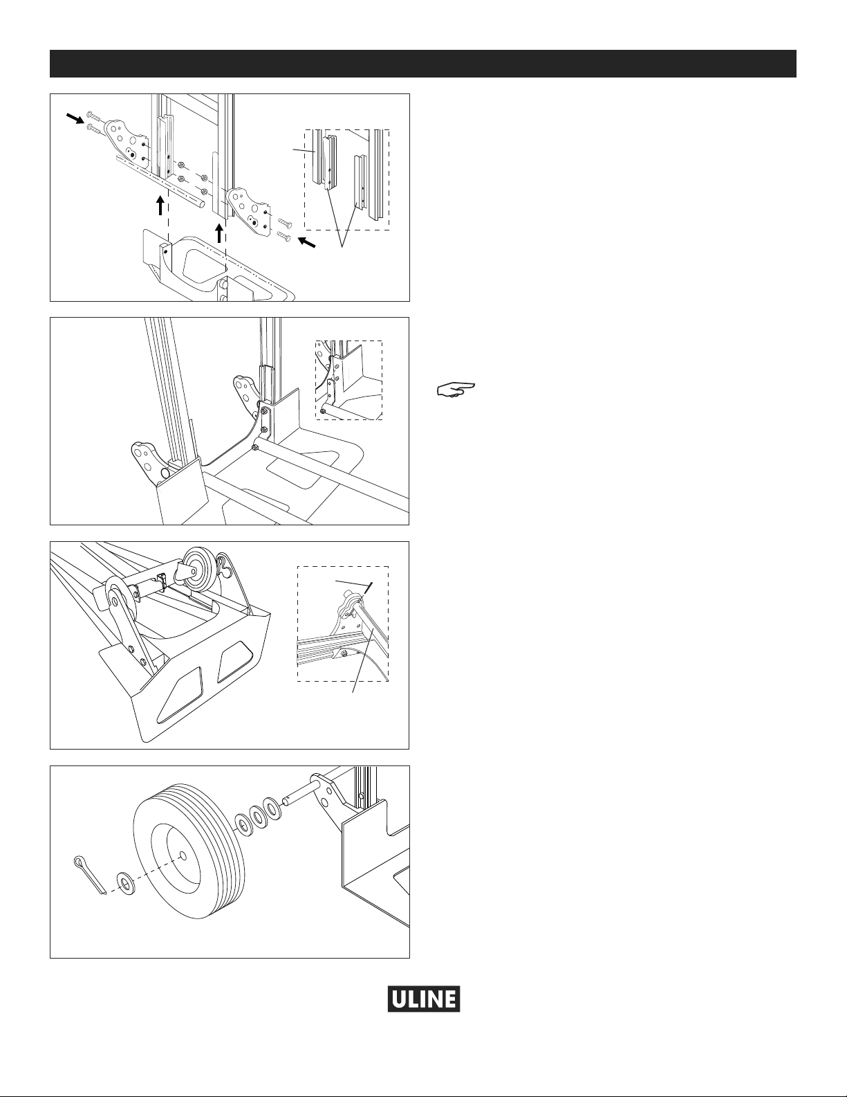
ASSEMBLY CONTINUED
1
0
uline.com
ATTACH NOSE PLATE, FOLDING NOSE EXTENSION
Figure 2a
AND AXLE SUPPORTS
Figure 2
Figure 3
Frame
Frame
Reinforcements
Figure 3a
1. Position frame reinforcements against bottom frame
rail. (See Figure 2a) Slide nose plate into channel on
frame reinforcements, keeping bolt holes aligned.
(See Figure 2)
2. Align axle support with outside rail of frame.
(See Figure 2)
3. Insert four 8mm bolts through the axle supports,
frame, frame reinforcements and nose plate.
(See Figure 2)
4. Slide the folding nose extension bracket over the
8mm bolts protruding from the bolt holes on the
inside of the nose plate. (See Figure 3a)
NOTE: The bolt holes on the bracket are NOT
centered. Make sure the bolt holes are closest
to the back of truck before tightening.
(See Figure 3)
5. Secure with locknuts but DO NOT tighten. (See Figure 3)
Figure 4
Figure 5
Figure 4a
Round
Pin
ATTACH AXLE AND WHEELS
1. Lay hand truck down on front so axle supports face
upwards. (See Figure 4)
2. Insert axle through holes in axle supports. Align holes
in axle with grooves on inside of the axle supports. Use
a hammer to tap in the round pins. (See Figure 4a)
Axle
3. Slide 3 washers onto each end of the axle. Slide
a wheel onto each end of the axle. Slide another
washer onto each end of the axle. (See Figure 5)
4. Insert a cotter pin through the holes in each end
of the axle. Bend cotter pins using pliers to secure
wheel. Wheels should spin freely. (See Figure 5)
5. Tighten all locknuts.
-800-295-551
PAGE 2 OF 6 0421 IH-4124
Page 3

H-4124
DIABLITO DE ALUMINIO
3-EN-1
CON LLANTAS DE
CAUCHO SÓLIDO
HERRAMIENTAS NECESARIAS
Llave de 10mm Llave de 13m m Llave de 14m m
80 0-295 -5510
uline.mx
Pinzas
Martillo
PARTES
1
2
7
6
3
4
9
6
8
2
11
10
12
4
15
9
13
6
11
14
10
5
6
REF. CANT. DESCRIPCIÓN
1 1 Asa
2 2 Perno de 6 mm
3 2 Contratuerca de 6mm
4 1 Armazón
5 2 Pasador
6 8 Rondana
7 2 Llanta
8 1 Eje
9 2 Perno Redondo
10 4 Perno de 8 mm
11 2 Soporte del Eje
12 2 Refuerzo del Armazón
13 4 Contratuerca de 8 mm
14 1 Base
15 1
Extensión Plegable
para la Base
5
ENSAMBLE
Diagrama 1
INSTALE EL ASA
1. Deslice el asa hacia los rieles superiores del
PAGE 3 OF 6 0421 IH-4124
NOTA: No utilice herramientas de aire o
eléctricas.
armazón. Alinee los orificios en el asa y el armazón.
Inserte dos pernos de 6 mm a través del armazón y
el asa y asegúrelos con contratuercas.
(Vea Diagrama 1)
Page 4

CONTINUACIÓN DE ENSAMBLE
8
0
uline.mx
INSTALE LA BASE, EXTENSIÓN PLEGABLE PARA LA
Diagrama 2a
BASE Y SOPORTES DEL EJE
Diagrama 2
Diagrama 3
Armazón
Refuerzos
del Armazón
Diagrama 3a
Diagrama 4a
Perno
Redondo
1. Posicione los refuerzos del armazón contra el fondo
del riel del armazón. (Vea Diagrama 2a) Deslice la
base dentro del canal en los refuerzos del armazón,
manteniendo los orificios de pernos alineados.
(Vea Diagrama 2)
2. Alinee el soporte del eje con el riel exterior del
armazón. (Vea Diagrama 2)
3. Inserte cuatro pernos de 8 mm a través de los
soportes del eje, el armazón, los refuerzos del
armazón y la base. (Vea Diagrama 2)
4. Deslice el soporte de la extensión plegable de la
base sobre los pernos de 8 mm que sobresalen de los
orificios en el interior de la base. (Vea Diagrama 3a)
NOTA: Los orificios de los pernos en el soporte
NO están centrados. Asegúrese de que los
orificios de los pernos estén en la posición más
cercana a la parte posterior del diablito antes
de asegurarlos. (Vea Diagrama 3)
5. Asegure con contratuercas pero NO apriete.
(Vea Diagrama 3)
INSTALE EL EJE Y LAS LLANTAS
1. Acueste el diablito hacia adelante a manera que
los soportes del eje estén hacia arriba.
(Vea Diagrama 4)
2. Inserte el eje a través de los orificios en los soportes
del eje. Alinee los orificios en el eje con muescas
en la parte interior de los soportes del eje. Use un
martillo para introducir los pernos redondos.
Eje
Diagrama 4
(Vea Diagrama 4a)
3. Deslice (3) rondanas sobre el extremo del eje.
Deslice una llanta en cada extremo del eje. Deslice
otra rondana en cada extremo del eje.
(Vea Diagrama 5)
4. Inserte un pasador a través de los orificios en cada
extremo del eje. Doble los pasadores usando pinzas
para asegurar la llanta. Las llantas deben girar
libremente. (Vea Diagrama 5)
5. Apriete todas las contratuercas.
Diagrama 5
00-295-551
PAGE 4 OF 6 0421 IH-4124
Page 5

H-4124
DIABLE 3-EN-1
AVEC ROUES EN
CAOUTCHOUC SOLIDES
OUTILS NÉCESSAIRES
Clé 10 mm Cl é 13 m m Clé 14m m
1-80 0-295 -5510
uline.ca
Pinces
Marteau
PIÈCES
1
2
7
6
3
4
9
6
8
2
11
10
12
4
15
9
13
6
11
14
10
5
6
RÉF. QTÉ. DESCRIPTION
1 1 Poignée
2 2 Boulon 6 mm
3 2 Écrou freiné 6 mm
4 1 Cadre
5 2 Goupille fendue
6 8 Rondelle
7 2 Roue
8 1 Essieu
9 2 Goupille ronde
10 4 Boulon 8 mm
11 2 Support d’essieu
12 2 Renfort de cadre
13 4 Écrou freiné 8 mm
14 1 Bavette
15 1
Rallonge de bavette
repliable
5
MONTAGE
Figure 1
FIXATION DE LA POIGNÉE
1. Glissez la poignée sur les rails supérieurs du cadre.
PAGE 5 OF 6 0421 IH-4124
REMARQUE : Ne pas utiliser d’outils à air ou
électrique.
Alignez les trous dans la poignée et le cadre. Insérez
deux (2) boulons de 6 mm à travers le cadre et la
poignée et fixez-les à l’aide d’écrous freinés.
(Voir Figure 1)
Page 6

Figure 2a
1
0
uline.ca
MONTAGE SUITE
FIXATION DE LA BAVETTE, DE LA RALLONGE DE
BAVETTE REPLIABLE ET DES SUPPORTS D’ESSIEU
Figure 2
Figure 3
Cadre
Renforts
de cadre
Figure 3a
1. Positionnez les renforts de cadre sur le bas des rails
de cadre. (Voir Figure 2a) Glissez la bavette dans le
canal des renforts de cadre, en gardant les trous de
boulons alignés. (Voir Figure 2)
2. Alignez les supports d’essieu avec le rail extérieur du
cadre. (Voir Figure 2)
3. Insérez quatre (4) boulons de 8 mm à travers des
supports d’essieu, du cadre, des renforts de cadre
et de la bavette. (Voir Figure 2)
4. Glissez le support de la rallonge repliable sur les
boulons de 8 mm saillants des trous de boulons à
l’intérieur de la rallonge de bavette. (Voir Figure 3a)
REMARQUE : Les trous de boulon du support ne
sont PAS centrés. Assurez-vous que les trous de
boulon sont positionnés plus près de l’arrière
du diable avant de serrer le tout. (Voir Figure 3)
5. Fixez avec les écrous freinés, mais NE serrez PAS.
(Voir Figure 3)
Figure 4
Figure 5
Figure 4a
Goupille
ronde
FIXATION DE L’ESSIEU ET DES ROUES
1. Posez le diable sur son devant de sorte que les
supports d’essieu sont orientés vers le haut.
(Voir Figure 4)
2. Enfilez l’essieu dans le trou des supports d’essieu.
Alignez les trous de l’essieu avec les rainures à
l’intérieur des supports d’essieu. Utilisez un marteau
pour planter les goupilles. (Voir Figure 4a)
Essieu
3. Enfilez trois (3) rondelles sur chaque extrémité de
l’essieu. Enfilez une (1) roue sur chaque extrémité
de l’essieu. Enfilez une autre rondelle sur chaque
extrémité de l’essieu. (Voir Figure 5)
4. Insérez une goupille fendue dans le trou à chaque
extrémité de l’essieu. Pliez les goupilles fendues à
l’aide de pinces pour sécuriser la roue. Les roues
doivent tourner librement. (Voir Figure 5)
5. Serrez tous les écrous freinés.
-800-295-551
PAGE 6 OF 6 0421 IH-4124
 Loading...