

Para Español, vea páginas 6-10.
Pour le français, consulter les pages 11-15.
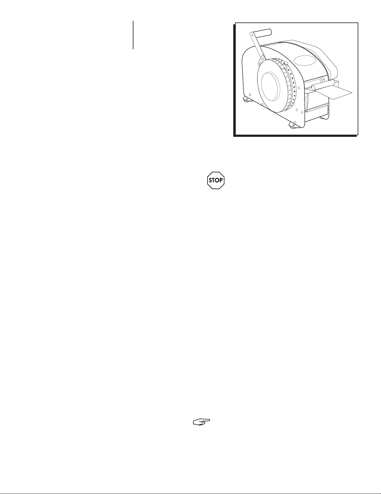
π H-35, H-669
BETTER PACK MANUAL
333 PLUS KRAFT TAPE
DISPENSER
1-800-295-5510
uline.com
IMPORTANT! Read this manual thoroughly
and familiarize yourself with ALL controls
and operating features. Keep this manual
for future reference and maintenance.
Unpacking: Check the machine for
damage. If damage is found, return to
Uline.
TECHNICAL DATA
Dimensions of Machine: 19⁄ x 9½ x 12⁄"
Water Bottle Capacity: 44 oz.
Tape Width: 1⁄ to 3"
Maximum Roll Size: Up to 600' of tape
Up to 7½" diameter roll
Tape Lengths Dispensed: Up to 30" in one stroke
(repeat pulls provide
unlimited lengths)
Shipping Weight: 22 lbs.
Brushes: 2
Power Requirements:
For H-35: None (Manual Dispenser)
For H-669: 75 Watts, 115 V
NOTE: All specifications subject to
change without notice.
PAGE 1 OF 15 0614 IH-35
GENERAL INFORMATION
BEFORE USING THE MACHINE
After removing the machine from the carton, check the
following items before storing the shipping cartons:
• Brush Tank and two Moistening Brushes: These are
packed inside the rear of the machine.
• Plastic Water Bottle: This is packed on the side of the
dispenser.
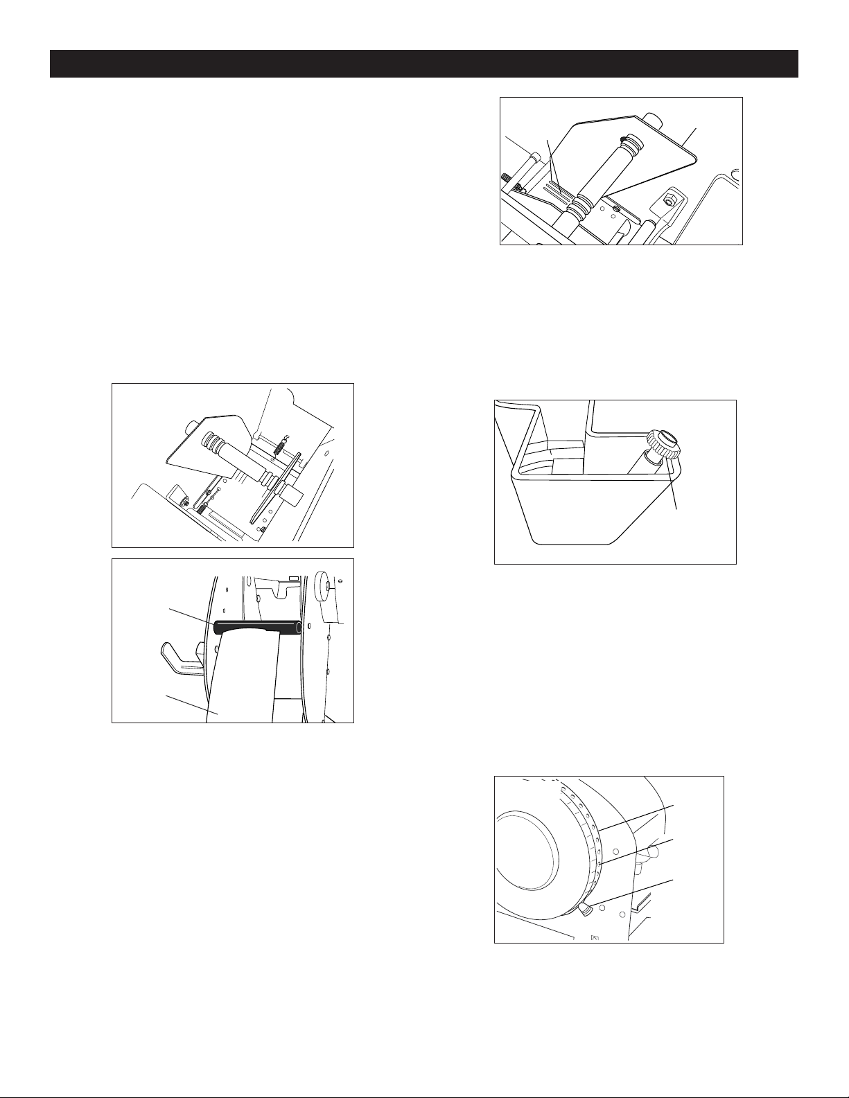
HEATER SETUP (FOR H-669 ONLY)
1. Locate the heater kit box.
2. Remove retaining ring. (See Figure 2)
Figure 2
Retaining
Ring
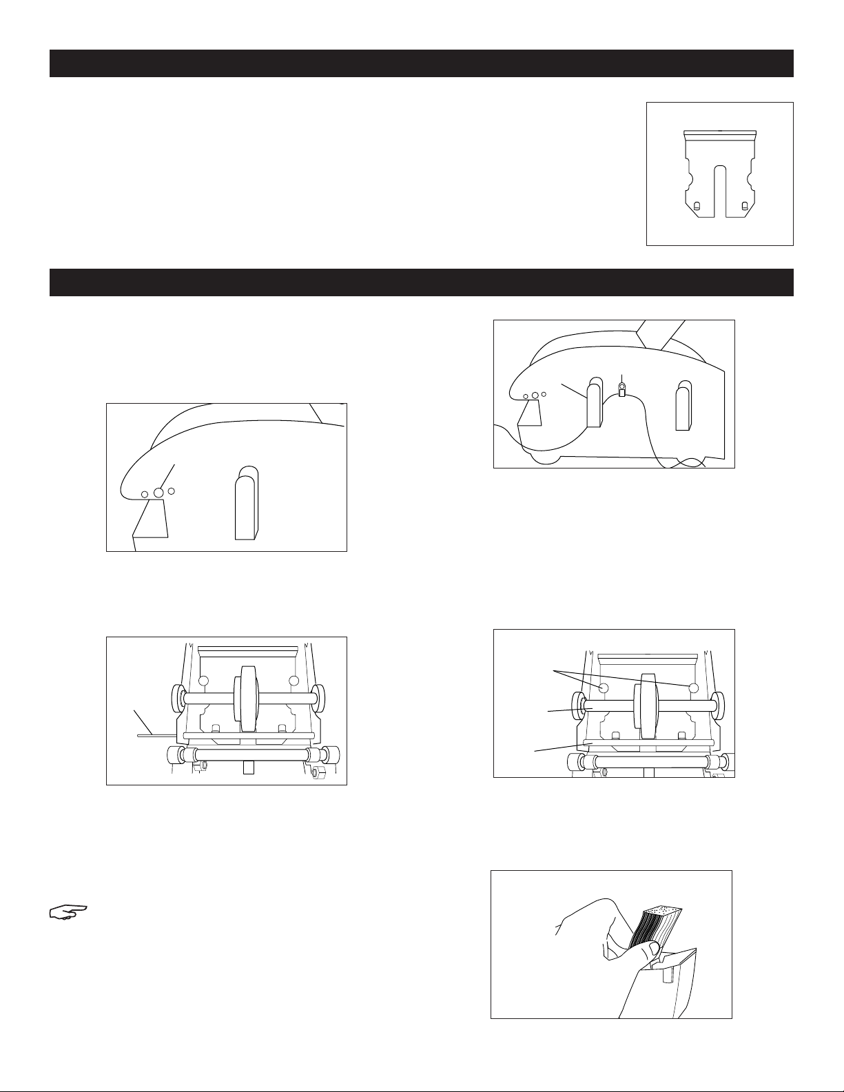
• Upper Tape Plate: This is
Figure 1
held in position by packing
material, but may have
become dislodged in
shipping. Remove tape, etc.
before using the machine.
(See Figure 1)
SETUP
Figure 4
Bottle
Bracket
SETUP
1. If the upper tape plate has been dislodged in
shipping, replace as follows:
Cord
Clamp
3. Remove shaft and gold rollers and set aside.
4. Install heater shaft with silver rollers from spare parts
bag. (See Figure 3)
Figure 3
Shaft
5. Use replacement retaining ring provided to hold the
shaft in place.
6. Direct the heater cord under the bottle bracket. Place
cord clamp on heater cord and, using screw and nut
provided, fasten to existing hole. (See Figure 4)
NOTE: Make sure there is enough slack in the
cord near the heater so the heater assembly
can pivot freely up and down.
With the slot towards the front of the machine, slide feed
wheel shaft under from rear until the cut-out portions
are over the retaining buttons. Allow the plate to slide in
place so that the front end of the plate is under the rod,
and the rear portion is under the buttons. (See Figure 5)
Figure 5
Retaining
Buttons
Feed
Wheel
Shaft
Rod
2. Wash out the moistening brushes in soap or mild
detergent and place both brushes into the tank so
the angle on the brushes slopes toward the rear of
the tank. (See Figure 6)
Figure 6
PAGE 2 OF 15 0614 IH-35
SETUP CONTINUED
3. Insert the tank into the opening on the front of the
machine, making sure the tank is behind the upward
lip on the tank shelf.
4. Fill the bottle with water and place in the bottle
holder so that the spout of the bottle is in the tank.
5. Adjust the roll guides for proper width of tape.
6. To load tape, take the roll of tape and peel off about
18 inches. Place the roll of tape in the basket so that
the strip of tape unwinds off the rear of the roll as
the leading end is brought towards the front of the
machine with the gummed side down. Thread the
tape over the black roller at the upper rear and slide
leading edge forward under the upper tape plate
and feed wheel. Close front and rear covers.
(See Figures 7a and 7b)
Figure 7a
Figure 8
Roll Guide
Slots
WATER LEVEL ADJUSTMENT
The amount of water required for proper moistening
of different grades of tape will differ. Heavier glues
or reinforced tapes will normally require higher levels
of water. Water level is controlled by the water level
adjustment screw located in the projecting portion of the
water tank. (See Figure 9)
Figure 9
Figure 7b
Black Roller
Tape
ADJUSTMENTS
TAPE WIDTH
The adjustable roll guides in the tape basket should be
properly set for the width of tape being dispensed. The
roll of tape should be centered between the frames
by threading the tape loosely between the roll guides,
which engage in slots in the basket and roll guide
separator.
To set the roll guides in position, lift them out of the slots in
the basket and tie rod. Slide to the desired position and
drop guides into slots in the bottom of the basket.
(See Figure 8)
Water Level
Adjustment
Screw
To raise the water level, turn the screw counterclockwise.
To decrease the water level, turn the screw clockwise.
REPEAT LENGTH STOP
The Better Pack 333 Plus is equipped with a feed stop. To
set for desired length, pull outwardly on the feed stop
until the pin disengages the hole in the drum skirt. Then
slide the feed stop assembly until the length desired
is set on the scale just above the feed stop assembly.
Release the knob, being sure the pin on the feed stop
engages with the proper hole in the skirt. (See Figure 10)
Figure 10
10
12
14
16
17
18
19
20
21
22
23
Drum
Skirt
Hole
Feed
Stop
PAGE 3 OF 15 0614 IH-35
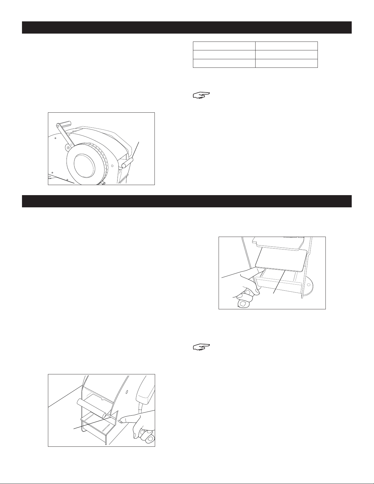
SETUP CONTINUED
CRANK HANDLE
If desired, the crank handle can be reversed.
PRESSURE PLATE WEIGHTS
The pressure plate, which rests on top of the brushes,
has removable weights. (See Figure 11) The number of
weights can be varied to suit the tape being dispensed.
Heavyweight tapes require more weight inserts than lighter
tapes. The suggested number of weights is as follows:
Fig ur e 11
Weights
10
12
14
16
17
18
19
20
21
22
23
MAINTENANCE AND CARE
MAINTENANCE
The best way to ensure long and carefree service
from your Better Pack 333 Plus is to KEEP IT CLEAN.
Tape dust, adhesive accumulation and other foreign
matters are harmful as they get into the working parts
of the machine. Likewise, be sure to wash the brushes
thoroughly at least once a week to ensure perfect
moistening, being careful to replace them with the
lower bevel to the back of the machine.
35 lb. Kraft Tape 0 to 1 Slug
60 lb. Kraft Tape 1 to 2 Slugs
Reinforced Tape 2 to 3 Slugs
The weights can be added or removed by pushing
them in or out from each side.
NOTE: If the machine consistently jams, there
is too much weight on the pressure plate and
some should be removed.
c. Reach inside the machine where tank was
removed, pull blade assembly down and swing
out to cleaning position. (See Figure 13)
TO CLEAN BLADE
Where reinforced tapes are used, it may be necessary
to periodically clean accumulation of laminate from the
cutting blade.
To clean the blade, follow these simple steps:
a. Remove water bottle and water tank assemblies.
b. Depress rocker stop rod protruding from the right
side of the machine with right hand and keep
it in this position until the blade assembly has
been released. (See Figure 12)
Figure 12
d. To clean blade: wipe off with suitable solvent.
When adhesive is removed, wipe with lightly
oiled cloth.
NOTE: DO NOT SCRAPE WITH HARD OBJECTS
as resulting scratches will quickly
accumulate adhesive.
e. Reinsert the blade to the cutting position by
depressing the rocker stop rod. Tip the blade
up into cutting position and push upward so the
blade will come between the stationary blade
rollers. Release rocker stop rod.
f. Try feeding and cutting tape to check if parts
are in proper position.
Rocker
Stop
PAGE 4 OF 15 0614 IH-35
g. Install tank and water bottle.
Blade
Assembly
Figure 13

SAFETY PRECAUTIONS
MUST READ BEFORE SERVICING EQUIPMENT
NOTE: This machine is designed for sealing
cartons with water-activated tape. Any
other use will void all warranties and any
responsibility or liability of Uline.
CAUTION! Read all Safety Precautions and
Operating Instructions before using this
machine.
CAUTION! Any operator of this machine must
be fully trained in its operation and safety.
WARNING! Keep the machine away from
children and from personnel who are not
authorized or adequately instructed in the
use of it.
π
CHICAGO • ATLANTA • DALLAS • LOS ANGELES • MINNEAPOLIS • NYC/PHILA • SEATTLE • MEXICO • CANADA
1-800-295-5510
PAGE 5 OF 15 0614 IH-35
uline.com
 Loading...