

Page 1
H -2917
ADJUSTABLE
PALLET TRUCK
1- 800 -295-5 510
uline.com
TECHNICAL DATA
MODEL H -2917
Capacity 5,500 lbs.
Max. Fork Height 7.7 "
Min. Fork Height 3.0"
Fork Length 45½"
Overall Fork Width 21-27"
Fork Wheel Diameter 3" Polyurethane
Steering Wheel Diameter 7" Polyurethane
Net Weight 204 lbs.
OPERATION
WARNING! Operator must read and understand
instructions here and on truck prior to use.
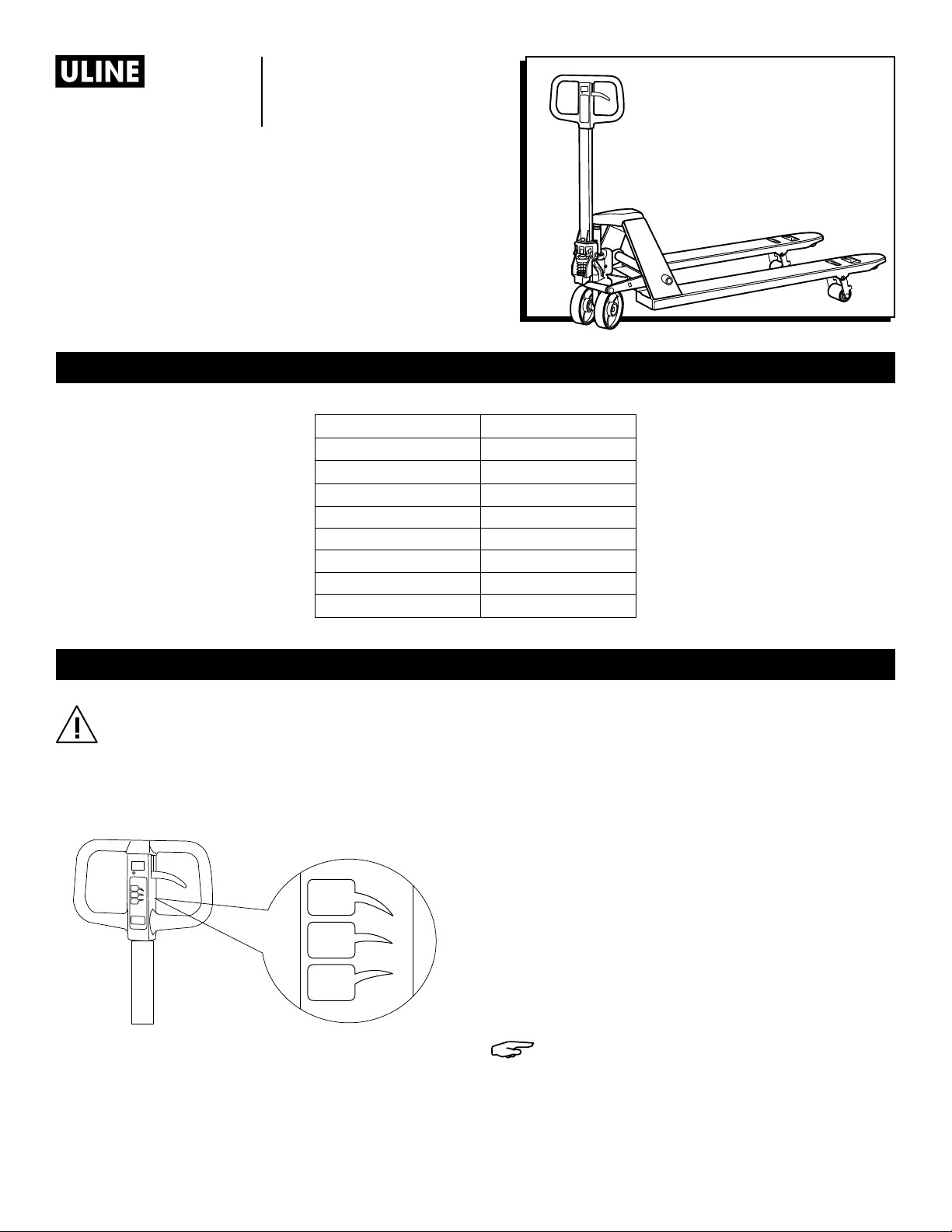
On the handle of the pallet truck, you will find the control
lever, which can be set in three positions.
(See Figure 1)
Figure 1
- UP = to raise the forks
- NEUTRAL = to move the load
- DOWN = to lower the forks
UP
N
DOWN
1. If the forks elevate while pumping in the NEUTRAL
position, turn the setting screw clockwise until
pumping the handle does not raise the forks and the
NEUTRAL position functions correctly.
2. If the forks descend while pumping in the NEUTRAL
position, turn the setting screw counterclockwise until
the forks do not lower.
3. If the forks do not descend when the control lever is
in the DOWN position, turn the setting screw clockwise
until raising the control lever lowers the forks. Then
check the NEUTRAL position as per steps 1 and 2.
4. If the forks do not lift while pumping in the UP position,
turn the setting screw counterclockwise until the forks
elevate while pumping in the UP position. Then check
the NEUTRAL and DOWN position as per steps 1, 2
and 3.
NOTE: When viewing the truck from the handle
side, the setting screw is located on the right
side of the pump above the right wheel. The
truck will lower faster or slower depending on
how far in or out the screw is adjusted.
0114 I H -2917PAGE 1 OF 6
Page 2
MAINTENANCE
OIL
Please check the oil level every six months.
Use the hydraulic oil SAE #10.
HOW TO EXPEL AIR FROM THE PUMP UNIT
Air may enter the unit over time or when the seals are
replaced. To expel the air, lift the control lever to the
DOWN position and move the handle up and down
several times.
SAFETY
For safe operation of the Hand Pallet Truck, please read
all warning signs and instructions here and on the pallet
truck prior to use.
1. Do not operate the pallet truck unless you are familiar
with it and have been trained and authorized to do so.
2. Do not use the truck on sloping ground.
3. Never place any part of your body in the lifting
mechanism or under the forks or load. Do not carry
passengers.
4. We advise that operators should wear gloves and
safety shoes.
DAILY CHECK AND MAINTENANCE
Daily checks of the pallet truck can limit wear and tear
on the unit. Pay special attention to the wheels, the axles,
the handle, the forks and lift and lower control.
LUBRICATION
Use motor oil or grease to lubricate all movable parts.
5. Do not handle unstable or loosely stacked loads.
6. Do not overload the truck.
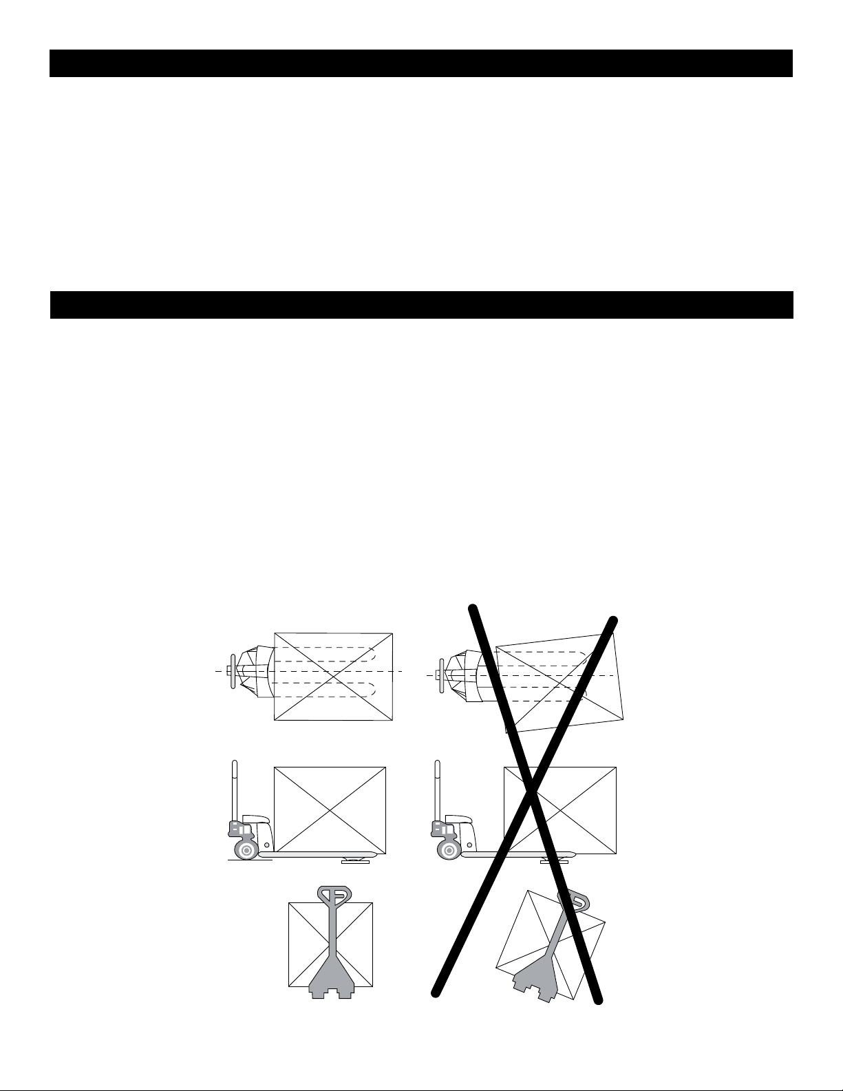
7. Always center loads on the forks, not at the end of the
forks. (See Figure 2)
8. The capacity of the truck assumes an evenly
distributed load with the center of the load being at
the halfway point of the length of the forks.
9. Make sure that length of the forks matches the length
of the pallet load.
10. Lower the forks to lowest height when the truck is not
being used.
Figure 2
A B
0114 I H -2917PAGE 2 OF 6
Page 3

ADJUSTING FORK WIDTH
Figure 3
Figure 4 Figure 6
Figure 5 Figure 7
1. Locate and remove the Allen wrench from its clip on
the truck body. (See Figure 3)
2. Loosen the screws on the front and back of each
fork of the truck. (See Figure 4)
3. Slide each fork to the desired position. (See Figure 5)
TROUBLESHOOTING
OPERATING ISSUE CAUSES RECOMMENDATIONS
The forks do not lift to
maximum height
Air in the hydraulic system
Insufficient hydraulic oil
4. Tighten the screws on each fork of the truck.
(See Figure 6)
5. Return the Allen wrench to its clip on the truck body.
(See Figure 7)
Expel the air (as noted in Maintenance)
Remove the oil plug (No. 25) and add oil
The forks do not lift
when the handle is
in lifting position
The forks drop after
every pump stroke
The forks do not lower
The forks drop when the handle
is in the neutral position
Forks lift when the handle is in
the neutral position
Insufficient hydraulic oil
Valve chain or setting screw are
out of alignment
Leak from valve cone (No. 16) assembly
Air in the hydraulic system
Leak from valve cone
Valve chain or setting screw are
out of alignment
Valve chain or setting screw are
out of alignment
Leak from the valve cone
Leak from the seal rings
Valve chain or setting screw are
out of alignment
Remove the oil plug (No. 25) and add oil
Adjust the valve chain with adjusting nut
(No. 71) or adjust the setting screw (as noted
in Operation)
Replace steel ball (No. 19)
Expel the air (as noted in Maintenance)
Replace valve cone (No. 16) valve housing
(No. 17), O-ring (No. 18) and O-ring (No. 13)
Adjust the valve chain with adjusting nut
(No. 71) or adjust the setting screw (as noted
in Operation)
Adjust the valve chain with adjusting nut
(No. 71) or adjust the setting screw (as noted
in Operation)
Replace valve cone (No. 16), valve housing
(No. 17), O-ring (No. 18) and O-ring (No. 13)
Replace cup packing (No. 43)
Adjust the valve chain with adjusting nut
(No. 71) or adjust the setting screw (as noted
in Operation)
Oil leaks from the pump
Seal ring damaged
or worn out
Replace O-ring (No. 32) and (No. 38)
0114 I H -2917PAGE 3 OF 6
Page 4

H -2917
ADJUSTABLE
PALLET TRUCK
1- 800 -295-5 510
uline.com
67
68
66
71
51
52
53
55
69
79
70
73
75
78
77
76
14
13
77
78
74
56
2
3
5
7
8
4
6
15
16
17
18
19
1
29
30
59
28
22
41
12
11
24
10
9
21
25
27
26
33
38
31
46
36
54
54
58
81
80
72
22
41
44
23
45
37
40
43
35
32
34
39
20
48
50
65
62
63
62
65
57
47
48
49
42
64
60
61
0114 I H -2917PAGE 4 OF 6
Page 5

H -2917
ADJUSTABLE
PALLET TRUCK
# DESCRIPTION QT Y. ULINE PART NO. MFG. PART NO.
1 Hydraulic Pump with Bypass 1 H-2917 P U MP 27015 0
2 Plunger Piston 1 ------------ 270101
3 Cap Washer 1 ------------ 270578
4 Spring 1 ------------ 270102
5 Dust Seal 1 ------------ 270103
6 Handle Base Bolt 1 ------------ 270313
7 Cup Packing 1 ------------ 270104
8 Nut 1 ------------ 270236
9 Roller 1 ------------ 270105
10 Bushing 1 ------------ 270105
11 Axle 1 ------------ 270105
12 Ball 1 ------------ 270105
13 O-Ring 1 ------------ 270106
14 Screw 1 ------------ 270107
15 Spring 1 ------------ 270108
16 Valve Cone 1 ------------ 270109
17 Valve Housing 1 ------------ 270110
18 O-Ring 1 ------------ 2 70111
19 Steel Ball 1 ------------ 27 0 112
20 Spring Pin 2 ------------ 270113
21 Axle 1 ------------ 270114
22 Screw 3 ------------ 270105
23 Handle Base 1 ------------ 270105
24 Spring Pin 1 ------------ 2 7 0116
25 Oil Plug 1 ------------ 270117
26 Axle Pin 1 ------------ 270118
27 Pin 1 ------------ 270119
28 Locking Ring 1 ------------ 270120
29 Spring Pin 1 ------------ 270121
30 Thrust Bearing 1 ------------ 270122
31 Spring 1 ------------ 270123
32 O-Ring 1 ------------ 270124
33 Relief Cylinder 1 ------------ 270576
34 Release Piston 1 ------------ 270125
35 Lowering Arm 1 ------------ 270126
36 Table Bolt 2 ------------ 270127
37 Dust Seal 1 ------------ 270128
38 O-Ring 1 ------------ 270268
39 Rubber Boot 1 ------------ 270267
40 O-Ring 1 ------------ 270129
41 Washer 2 ------------ 270115
1- 800 -295-5 510
uline.com
0114 I H -2917PAGE 5 OF 6
Page 6

H -2917
ADJUSTABLE
PALLET TRUCK
# DESCRIPTION QT Y. ULINE PART NO. MFG. PART NO.
42 Load Wheel Pin 2 ------------ 270265
43 Cup Packing 1 ------------ 270131
44 Ball 1 ------------ 270132
45 Ram Piston 1 ------------ 270133
46 Wheel Shaft 1 ------------ 270134
47 Steering Wheel 2 H-2917 S T WH L 270785
48 Ball Bearing 4 H-2917BBRNG 270273
49 Locking Ring 2 H-2917-LKRNG 270137
50 Cap 2 H -2 917-C A P 270314
51 Nut 1 ------------ 270581
52 Screw 1 ------------ 270 581
53 Pivot Rod 1 ------------ 270 575
54 Fork 2 ------------ 270772
55 Spring Pin 1 ------------ 270272
56 Adjustable Tie Rod 2 H - 2 917- T RO D 270773
57 Load Wheel Yoke 2 ------------ 270263
58 Pin 2 H-2917RODPIN 270264
59 Yoke 2 ------------ 270284
60 Axle 1 ------------ 270144
61 Spring Pin 1 ------------ 270266
62 Ball Bearing 4 ------------ 270273
63 Load Wheel 1 ------------ 270288
64 Axle 2 ------------ 270145
65 Nylon Cover 4 ------------ 270289
66 Coated Handle (Part Of A Kit) 1 ------------ 270141
67 Handle (Part Of A Kit) 1 ------------ 27 0141
68 Spring Pin (Part Of A Kit) 1 ------------ 270141
69 Pull Pole (Part Of A Kit) 1 ------------ 270141
70 Adjustment Rod (Part Of A Kit) 1 ------------ 270141
71 Adjustment Nut (Part Of A Kit) 1 ------------ 270141
72 Exit Roller 2 ------------ 270821
73 Frame 1 ------------ 270774
74 Fixity 2 ------------ 270775
75 Fixity 2 H-2917-75 270790
76 Screw 2 H - 2 917-76 270777
77 Spring Washer 6 H-2917-77 270778
78 Washer 6 H -2917-78 270779
79 Screw 4 ------------ 270780
80 Adjust Screw 2 ------------ 270782
81 Adjust Screw Nut 2 ------------ 270783
1- 800 -295-5 510
uline.com
π
CHICAGO • ATL ANTA • DALL AS • LOS ANGELES • MINNE APOLIS • NYC/PHIL A • SEATTLE • MEXICO • CANADA
0114 I H -2917PAGE 6 OF 6
 Loading...